

Page 1
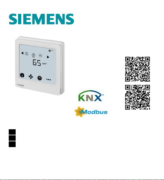
RDF870KN
RDF870MB
PM2.5 & IAQ
Control
en Touch Screen Room Controller / Room Unit Operating Instructions
de Raumregler mit Touchscreen / Raumgerät-Bedienungsanleitung
zh 触摸屏房间控制器/房间单元操作手册
A6V11439451_----_c 1
Open Source
Software (OSS)
Page 2

BLANK PAGE
Leere Seite
空白页
2 A6V11439451_----_c
Page 3
Introduction
Reference
pages
Application
Installation
Parameters
A6V11439451_----_c 3
Terminals
RDF870KN RDF870MB
L, N L, N AC 230 V operating voltage
Q1, Q2, Q3, Q4 Q1, Q2, Q3, Q4
X1, X2
M M Input reference ground
Y50 Y50 DC 0…10 V output
CE+, CE- - KNX bus + and - terminals
- A+, B- Modbus + and - terminals
- REF Modbus reference ground
X1, X2
Description
Fan relay with max four speeds
outputs
Multifunctional inputs 1 & 2
Page 4
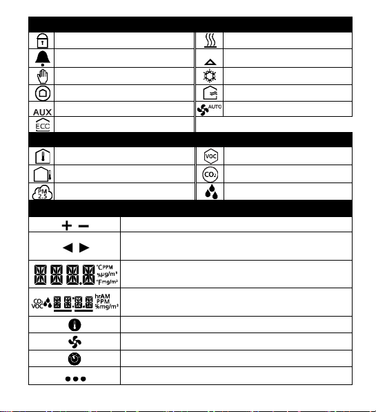
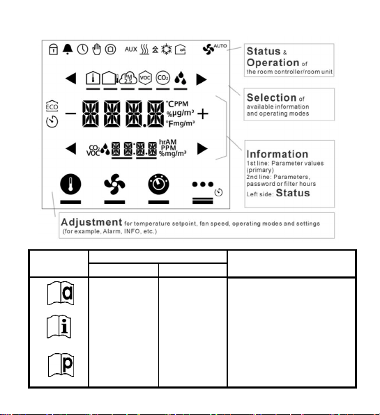
Status symbols:
Screen lock Heating mode
Alarm / Service reminder Valve on
Manual override Cooling mode
Protection mode Ventilation mode
Auxiliary heating active Auto fan mode
Economy mode
Selection symbols:
Room temperature VOC mode
Outdoor temperature CO2 mode
PM2.5 mode Relative humidity
Operational icons:
Increment, decrement or selection
Selection, change or move to previous or next
items
Display values, relative humidity or parameter
values, etc.
Secondary display, parameters, password /
filter hours
Setpoint mode
Fan mode or fan speed mode
Operating mode
More functions or info
4 A6V11439451_----_c
Page 5
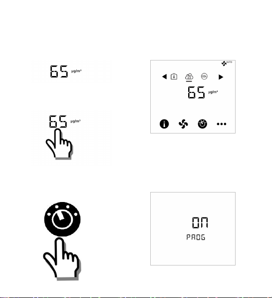
Commissioning: Download via ETS
Note: This operation applies to RDF870KN only.
1. Screen idle 3. Normal display
2. Touch digits / screen
4. Touch & hold
icon > 5 s to enter
5. Ready for downloading
address & application
Programming mode
Touch “ON“ to exit
A6V11439451_----_c 5
Page 6
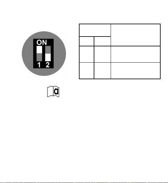
Commissioning: Local via DIP switches
1. Set application via
DIP switches
Refer to
2. Configure basic
control parameters
See Parameters on page
17.
6 A6V11439451_----_c
DIP switch
positions
1 2
ON OFF Room unit
OFF OFF Room controller
DIP switch setting applies to
RDF870MB only.
Current factory setting for PM2.5
control with 3 speed on/off fan
application:
· APP= 1: PM2.5 control only
· DISP: Room temp= 1; PM2.5= 1
· SEN1= 3: PM2.5 (AI) μg/m
· SEN2= 0: no function
· FAN= 3: 3 speed fan
Application
3
(0…10 V)
Page 7

Idle screen shows default PM2.5
1. Screen idle 3. Normal display / mode
2. Touch digits / screen
PM2.5
CO2 Room temperature
Normal display for ventilation
1. Screen idle 3. Normal display / mode
2. Touch digits / screen
A6V11439451_----_c 7
Page 8
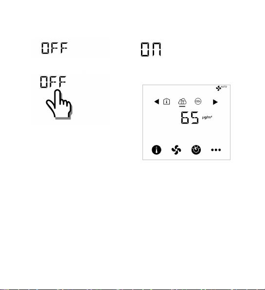
If unit is OFF
1. Screen idle 3. Unit being turned ON
2. Touch digits / screen 4. Normal display / mode
PM2.5 as default display value
8 A6V11439451_----_c
Page 9
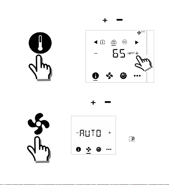
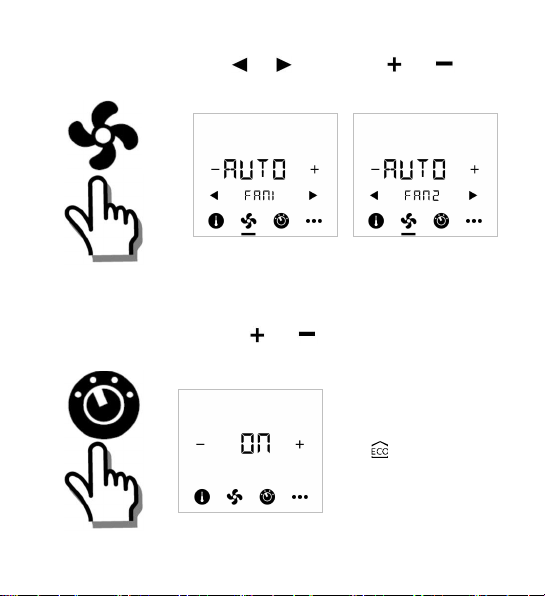
Adjust setpoint
1. Touch icon 2. Press or to adjust:
Single fan: On/Off only
1. Touch icon
A6V11439451_----_c 9
2. Press or to adjust:
Change fan mode:
ON > AUTO
See for fan
type selection.
Page 10
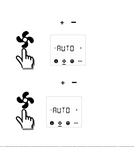
Fan speed selection
Fan speed is adjusted by
Adjust 3- or 4-speed fan:
1. Touch icon
Adjust ECM fan:
1. Touch icon 2. Press or to adjust:
10 A6V11439451_----_c
2. Press or to adjust:
Auto
1: Speed 1
2: Speed 2
3: Speed 3
4: Speed 4
Depends on fan
type selection
percentage.
· Touch + or – once to
adjust speed by 5 %.
· Press and hold + or –
to quickly adjust
speed.
(See Min./Max.
settings in
Engineering mode
parameters)
Page 11
Dual fan operations (RDF870MB RU only)
1. Touch icon 2. Use or and press or to
adjust:
FAN1 FAN2
depends on fan type selection and fan number configuration
Change operating modes
1. Touch icon 2. Press or to select:
ON: Comfort mode
ECO : Economy mode, a
symbol will be
shown
OFF: OFF
A6V11439451_----_c 11
Page 12
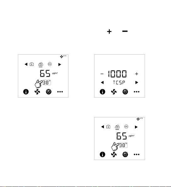
Adjust timer (Fan filter alarm)
Change timer setpoint (TCSP) default value:
1. Touch timer area
once to enter time
counter setting
Reset timer:
Press and hold timer
area more than 10 s to
reset timer to 0
12 A6V11439451_----_c
2. Press or to adjust:
Page 13
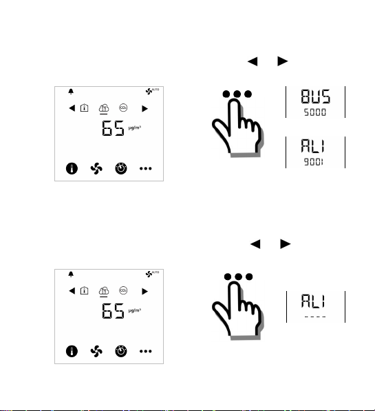
View alarms (RDF870KN)
1. When alarm bell is
displayed
2. Touch icon once and
press or to view
all alarms
For alarms, see alarm table on
page 14.
View alarms (RDF870MB)
1. When alarm bell is
displayed
A6V11439451_----_c 13
2. Touch icon once and
press or to view
all alarms
For alarms, see to alarm table
on page 14.
Page 14
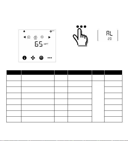
View alarms (RDF870MB room unit)
1. When alarm bell is
displayed
Priority Alarm/Service Display Error code * Type Product
1 Bus power supply
2 Device address error
4 External fault input 1
5 External fault input 2
6 Clean filter reminder
7 Internal sensor error
8 EEPROM error
9 External error
*
Error codes are for RDF870KN only.
14 A6V11439451_----_c
2.
Alarm AL originates in the
controller when RDF870MB
works as a room unit.
BUS 5000 Fault RDF870KN
Adr 6001
AL1 9001 RDF870..
AL2 9002
FIL 3911
Er1 Er2 Er3 -
-
RDF870KN
RDF870..
RDF870..
RDF870..
RDF870..
RDF870..
Page 15
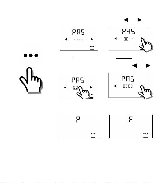
Parameter mode user access
1. Touch &
hold icon
> 5 s
2. Enter first password via or
PAS: Password
Factory: 00 00
3. Enter second password via or
Note: Press the
Setting icon to exit
or re-enter the
password if not
correct
4. After 6 seconds
P: Successful login F: Failed login
A6V11439451_----_c 15
Page 16
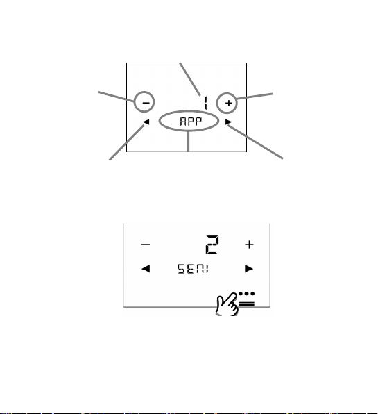
5. Edit parameters
via
Value of current
selected parameter
Decrement
or
Previous
available value
Previous
parameter
current selected
Parameter
Increment
Next
available value
Next
parameter
6. Exit parameter mode
Touch the setting
mode icon to exit
16 A6V11439451_----_c
Passwords can
be modified
both HMI and
or
NOTE:
system.
Page 17
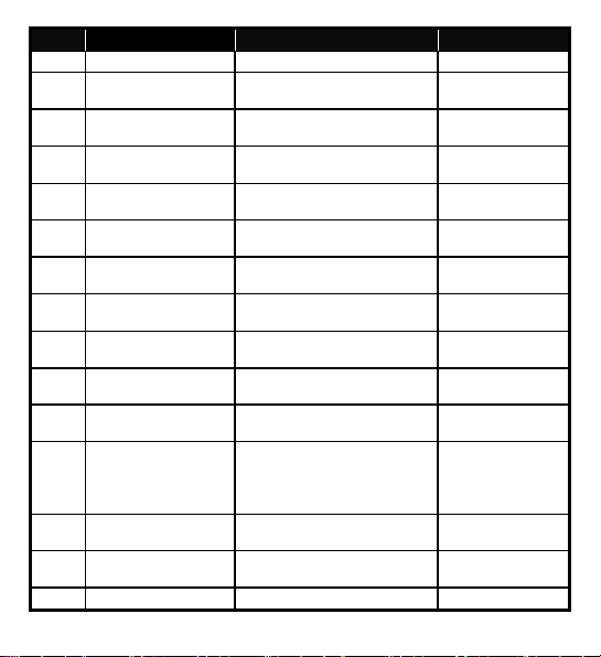
Engineering parameters
setting
3: 38400
bps
4: Ventilation
6)RH=
0;
External sensor1 type
Item Description Range Factory settings
Modbus address
MODA
Modbus baud rate
MODB
setting
Modbus data frame
MODF
format
Application selection 1: PM2.5 control only
APP
Symbol display
DISP
enable/disable
1)
SEN1
selection
A6V11439451_----_c 17
1…247 1
1: 9600 bps
2: 19200 bps
0: 1/8/E/1
1: 1/8/O/1
2: 1/8/N/1
3: 1/8/N/2
2: PM2.5 + CO2 control
3: CO2 control only
0: Disable display
1: Enable display
0: No function
1: Temperature (AI)
(NTC 10k)
2: Temperature (AI)
(0…10 V)
3: PM2.5 (AI) μg/m
(0…10 V)
4: CO2 (AI) ppm (0…10 V)
5: VOC (AI) % (0…10 V)
3
2: 19200 bps
0: 1/8/E/1
1: PM2.5 control
only
1) Room Temp= 1;
2) Outside
Temp= 0;
3) PM2.5= 1;
4) VOC= 0;
5) CO2= 0;
3: PM2.5 (AI)
μg/m
(0…10 V)
3
Page 18
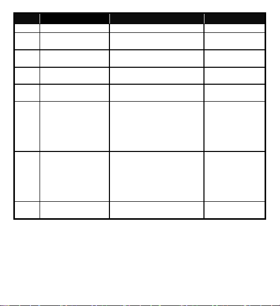
Item Description Range Factory settings
digital input
1: Normally closed /
Close
d
Open
External sensor2 type
digital input
1: Normally closed /
Close
d
Open
range
range
6: VOC (AI) mg/m³ (0…10 V)
7: R.h. (AI) % (0…10 V)
8: Alarm input (DI)
9: Dummy AI (0…10 V)
(RU only)
Operating action if
DIL1
1)
SEN2
selection
Operating action if
DIL2
PM2.5 sensor high
PMH
PM2.5 sensor low
PML
CO2 sensor high
CO2H
range
18 A6V11439451_----_c
10: Dummy DI (RU only)
0: Normally open / Open
0: No function
1: Temperature (AI)
(NTC 10k)
2: Temperature (AI)
(0…10 V)
3: PM2.5 (AI) μg/m
(0…10 V)
4: CO2 (AI) ppm (0…10 V)
5: VOC (AI) % (0…10 V)
6: VOC (AI) mg/m³ (0…10 V)
7: R.h. (AI) % (0…10 V)
8: Alarm input (DI)
9: Dummy AI (0…10 V)
(RU only)
10: Dummy DI (RU only)
3
0: Normally open / Open
0: Normally open /
0: No function
0: Normally open /
Max. of low range…1000 500
0…Min. of high range 0
Max. of low range…2000 2000
Page 19
Item Description Range Factory settings
range
Humidity sensor high
range
high range
low range
range
range
high
low
CO2 sensor low range 0…Min. of high range 0
CO2L
VOC sensor high
UOCH
VOC sensor low
UOCL
range
HUMH
range
Humidity sensor low
HUML
Temperature sensor
TEMH
Temperature sensor
TEML
PM2.5 setpoint high
SPMH
range
PM2.5 setpoint low
SPML
range
CO2 setpoint high
SPCH
CO2 setpoint low
SPCL
Fan type selection 1: 1 speed fan (ON/OFF)
FAN
ECM fan output limit
ECMH
ECM fan output limit
ECML
Filter time display 0: Disable 0: Disable
TC
A6V11439451_----_c 19
Max. of low range…100 5
0…Min. of high range 0
Max. of low range…100 100
0…Min. of high range 0
Max. of low range…100 50
-50…Min. of high range 0
Max. of low range…500 100
0…Min. of high range 12
Max. of low range…2000 1500
0…Min. of high range 500
3: 3 speed fan
3: 3 speed fan
4: 4 speed fan
5: ECM fan
Max. of ECML…100 % 80 %
0…Min. of ECMH 30 %
Page 20
Item Description Range Factory settings
setting
1: Enable
1: Enable
1: °F (degrees Fahrenheit)
Celsius)
only
u
nitonly)
sensor calibration
2)
PM2.5 ECO mode
PMES
setpoint
2)
CO2 ECO mode
COES
setpoint
Buzzer function 0: Disable
BUZZ
Temperature unit 0: °C (degrees Celsius)
UNIT
Keylock function 0: Unlock
LOCK
0…100 60
500…1500 1000
1: Enable
0: °C (degrees
0: Unlock
1: Locked
2: Setpoint only
3: Operating mode only
4: Setpoint and fan speed
OPSL
Operating mode
selection
0: ON/OFF
1: ON/ECO/OFF
2: ON/ECO/Protection/OFF
(RU only)
1: ON/ECO/OFF
3: ON/ECO/Protection (room
Internal temperature
CALT
20 A6V11439451_----_c
-5…5 K 0
Page 21

RDF870KN available parameters and their order of appearance:
· Room controller:
APP > DISP > SEN > FAN > OPSL > TC > UNIT > LOCK > BUZZ > CALT > APP
RDF870MB available parameters and their order of appearance:
· Room controller:
MODA > MODB > MODF >APP > DISP > SEN > FAN > OPSL > TC > UNIT
> LOCK > BUZZ > CALT > MODA
· Room unit:
MODA > MODB > MODF > LOCK > BUZZ > CALT > MODA
1)
Room controller: 0…8; Room unit: 0…10
2)
The setpoint cannot be changed in ECO mode.
Restriction for sensor selection:
1. If SEN1 and SEN2 are configured with the same selection type 1…8, they
cannot be the same sensor types:
· For type 1…8, sensor1 cannot be the same as sensor2.
· For sensor types with the same function such as 1&2 or 5&6, if
one sensor type is 1 or 5, the other one cannot be 2 or 6.
A6V11439451_----_c 21
Page 22
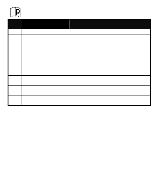
Firmware Setpoint Settings
TCSP
Filter time
setting
0…9
999
8760
range
high
range
low
mg/m3: 0…5
6
%
Item Description Range Factory
PM2.5SPPM2.5 setpoint SPML…SPMH 60
CO2 SP CO2 setpoint SPCL…SPCH 1000
T SP Temperature setpoint T SP L…T SP H 24
T SP H Temperature setpoint
T SP L Temperature setpoint
VOC SP VOC setpoint %: 0…100
HUMSPHumidity setpoint 0…100 % 50 %
P811) Device address (KNX
only)
1)
P81 is only for ETS and local HMI does not support P81:
· During powering up, there is a startup delay (TwaitDevice = tWaitMin +
DeviceAdr * 200ms) before the processing signal is processed.
· When P81=255(default), the device does not process the signal
according to heartbeat and COV mechanism. But it can respond when
another device is polling.
· The local HMI does not support P81.
· When individual address is changed via ETS, P81 is updated
automatically after device downloads it from ETS.
22 A6V11439451_----_c
Max. of low range…200 (°C) 50
-50…Min. of high range (°C) 5
1…255 255
settings
0.6 mg/m3 or
Page 23
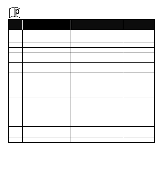
Expert Mode Parameters
settings
PMI
PM2.5 c
ontrol factor
Tn
0…120
min45min
CO2I
CO2control factor
Tn
0…120
min45min
deadband
(dwell time)
SW
Software version
XPAS
Expert mode password
5000…9999
9999
Item Description Range Factory
PMP PM2.5 control factor Xp 0…1000 50
CO2P CO2 control factor Xp 0…2000 100
PMDB PM2.5 control loop
CODB CO2 control loop
deadband
OPAF Operating mode settings
after power failure/reset
FANT Fan minimum on time
FSET Reload factory settings 0: OFF = Disable
EPAS Engineer mode password 0000…4999 0000
Room controller workflow:
EPAS > XPAS > PMP > PMI > PMDB > CO2P > CO2I > CODB > OPAF > FANT >
FSET > SW > EPAS
RDF870MB Room unit workflow: EPAS > XPAS > SW > EPAS
A6V11439451_----_c 23
0…20 10
0…100 50
0: Return to previous
operating mode / user
setting
1: Off
1…6 min 2 min
1: ON = Reload start
“--””---””----” is displayed
while reloading
0: Return to
0: OFF = Disable
previous
operating
mode / user
setting
Page 24

Other Parameters (RDF870MB room unit only)
Item Description Range Factory
Output 1 (Q1) Output for external Modbus
controller (master)
Output 2 (Q2) Output for external Modbus
controller (master)
Output 3 (Q3) Output for external Modbus
controller (master)
Output 4 (Q4) Output for external Modbus
controller (master)
0: Off
1: On
0: Off
1: On
0: Off
1: On
0: Off
1: On
For complete parameter list, please refer to the document listed in
the following table.
Ref. Document title Document number
[1] Datasheet A6V11439454
Download above document from http://siemens.com/bt/download by
searching for the document number.
24 A6V11439451_----_c
settings
0: Off
0: Off
0: Off
0: Off
Page 25

BLANK PAGE
Leere Seite
空白页
A6V11439451_----_c 25
Page 26

Einführung
Referenz-
seiten
Applikation
Installation
Parameter
26 A6V11439451_----_c
Klemmen
RDF870KN RDF870MB
L, N L, N AC 230 V Betriebsspannung
Q1, Q2, Q3, Q4 Q1, Q2, Q3, Q4
X1, X2
M M Messnull
Y50 Y50 DC 0 bis 10 V Ausgang
CE+, CE- - KNX Bus + und Klemmen
- A+, B- Modbus + und Klemmen
- REF Modbus Referenzerde
X1, X2
Beschreibung
Max. 4-stufige
Ventilator-Relaisausgängen
Multifunktionale Eingänge 1 & 2
Page 27

Statussymbole:
Bildschirmsperre Heizen
Alarm/Serviceerinnerung Ventil Ein
Manuelle Übersteuerung Kühlen
Schutzbetrieb Lüften
Stützbetrieb Heizen aktiv Auto-Ventilatorbetrieb
Economy-Betrieb
Auswahlsymbole:
Raumtemperatur VOC-Betrieb
Aussentemperatur CO2- Betrieb
PM2.5-Betrieb Relative Feuchtigkeit
Bediensymbole:
Auswahl mehr, weniger
Auswählen, ändern oder weiter zum
vorherigen oder nächsten Element
Anzeigewerte, relative Feuchtigkeit oder
Parameterwerte usw.
Sekundäranzeige, Parameter
Passwort/Filterstunden
Sollwert
Ventilator oder Ventilatorstufe
Betriebsart
Weitere Funktionen oder Info
A6V11439451_----_c 27
Page 28

Inbetriebnahme: Download über ETS
Hinweis: Gilt nur für RDF870KN.
1. Anzeige inaktiv 3. Standardanzeige
2. Anzeige antippen
4. Symbol > 5 s
halten für
5. Bereit für Download von
Adresse & Applikation
Programmierungsbetrieb
Mit “Ein“ verlassen
28 A6V11439451_----_c
Page 29

Inbetriebnahme: Lokal über DIP-Schalter
1. Applikation über
DIP-Schalter
einstellen
DIP-Schalter
Stellung
1 2
ON OFF Raumgerät
OFF OFF Raumregler
DIP-Schalter-Stellung gilt nur für
RDF870MB.
Applikation
Siehe
2. Basisparameter
konfigurieren
Siehe Parameter auf S. 40.
A6V11439451_----_c 29
Aktuelle Werkseinstellung für
PM2.5-Regelung mit 3-stufiger
Ein/Aus-Ventilatorapplikation:
• APP= 1: Nur PM2.5 Regelung
• DISP= 1: Raumtemp & PM2.5
• SEN1= 3: PM2.5 (AI) μg/m
(0…10 V)
• SEN2= 0: Keine Funktion
• FAN= 3: 3-stufiger Ventilator
3
Page 30

Ruhebildschirm zeigt Standard PM2.5
1. Anzeige inaktiv 3. Normalbetrieb
2. Anzeige antippen
PM2.5
CO2 Raumtemperatur
Standardanzeige für Lüften
1. Anzeige inaktiv 3. Normalbetrieb
2. Anzeige antippen
30 A6V11439451_----_c
Page 31

Bei Einheit Aus
1. Anzeige inaktiv 3. Einheit wird eingeschaltet
2. Anzeige antippen 4. Normalbetrieb
PM2.5 als Standardanzeigewert
A6V11439451_----_c 31
Page 32

Sollwert anpassen
1. Symbol antippen 2. oder drücken:
Einstufiger Ventilator: Nur Ein/Aus
1. Symbol antippen
32 A6V11439451_----_c
2. oder drücken:
Ventilator ändern:
Ein > Auto
Siehe für
VentilatortypAuswahl
Page 33

Ventilatorstufen-Auswahl
3- oder 4-stufigen Ventilator einstellen:
1. Symbol
antippen
ECM-Ventilator einstellen:
1. Symbol
antippen
A6V11439451_----_c 33
2. oder drücken:
Auto
1: Stufe 1
2: Stufe 2
3: Stufe 3
4: Stufe 4
Abhängig von der
Ventilatortyp-Auswahl
2. oder drücken:
Ventilatorstufe wird
prozentual eingestellt.
· + oder – einmal
drücken, um Stufe je
um 5% anzupassen
· + oder – gedrückt
halten passt die Stufe
schnell an.
(Min./Max. Einstellungen in
EngineeringParameter)
Page 34

Doppelventilatorbetrieb (nur RDF870MB RU)
1. Symbol
antippen
2. Mit oder und oder
anpassen:
Ventilator1 Ventilator2
Abhängig von Ventilatortyp-Auswahl und -konfiguration
Betriebsarten ändern
1. Symbol
antippen
34 A6V11439451_----_c
2. oder drücken und wählen:
ON: Komfortbetrieb
ECO : Economy-Betrieb,
wird angezeigt
OFF: Aus
Page 35

Zeitschalter anpassen (Ventilatorfilter-Alarm)
Zeitschalter-Vorgabesollwert (TCSP):
1. Zeitbereich einmal
antippen für
Einstellung
Zeitschalter
Zeitschalter zurücksetzen:
Zweitschalterbereich
mehr als 10 s drücken,
um auf 0 zurückzusetzen
A6V11439451_----_c 35
2. oder drücken:
Page 36

Alarme anzeigen (RDF870KN)
1. Sobald Alarmglocke
angezeigt wird
2. Symbol antippen und
oder drücken, um
alle Alarme anzuzeigen
Siehe Alarmtabelle auf Seite 37.
Alarme anzeigen (RDF870MB)
1. Sobald Alarmglocke
angezeigt wird
36 A6V11439451_----_c
2. Symbol antippen und
oder drücken, um
alle Alarme anzuzeigen
Siehe Alarmtabelle auf Seite 37.
Page 37

Alarme anzeigen (RDF870MB ROOM UNIT)
Priorität
Alarm/Service
Anzeige
Fehlercode
*
Typ
Produkt
Adr
6001-RDF870KN
Externer
Störungseingang 1
Externer
Hinweis Filter
reinigen
Interner
Er2
-
1. Sobald Alarmglocke
angezeigt wird
2.
Alarm AL stammt vom Regler,
wenn RDF870MB das
Raumgerät ist.
1 Busspeisung
2 Geräteadressfehler
4
5
Störungseingang 2
6
7
8 EEPROM-Fehler
9 Externer Fehler
*
Die Fehlercodes betreffen nur RDF870KN.
A6V11439451_----_c 37
Fühlerfehler
BUS 5000 Fault RDF870KN
AL1 9001 RDF870..
AL2 9002 RDF870..
FIL 3911 RDF870..
Er1 - RDF870..
Er3 -
RDF870..
RDF870..
Page 38

Parameterbetrieb Benutzerzugriff
1. Symbol
gedrückt
halten > 5 s
2. Eingabe 1. Passwort über oder
PAS: Passwort
Werkseinstellung:
00 00
3. Eingabe 2. Passwort über oder
Hinweis: Symbol
für Einstellung auf
Schliessen drücken
oder Passwort
erneut eingeben
4. Nach 6 Sekunden
P: Anmeldung ok F: Anmeldungsfehler
38 A6V11439451_----_c
Page 39

5. Parameter bearbeiten
Wert des aktuell gewählten
Parameters
Abwärts
oder
vorheriger
verfügbarer Wert
Vorheriger
Parameter
Aktuell gewählter
Parameter
Aufwärts
oder
nächster
verfügbarer Wert
Nächster
Parameter
6. Parameterbetrieb schliessen
Hinweis:
Schliessen durch
Antippen des
Symbols für
Einstellung
A6V11439451_----_c 39
Passwörter
können über
HMI und das
System
geändert
werden
Page 40

Engineering-Parameter
3: 1/8/N/2
7:
r.F.
(AI) %(0…10
V)
μ
g
Elem. Beschreibung Bereich Werkseinstellungen
Modbus Address-
MODA
einstellung
Modbus Baudraten-
MODB
Einstellung
Modbus Daten-
MODF
Frame-Format
Applikationsauswahl 1: Nur PM2.5-Regelung
APP
Symbolanzeige
DISP
aktivieren/
deaktivieren
1)
Externer Eingang X1
SEN1
Typenauswahl
40 A6V11439451_----_c
1…247 1
1: 9600 bps
2: 19200 bps
3: 38400 bps
0: 1/8/E/1
1: 1/8/O/1
2: 1/8/N/1
2: PM2.5 + CO2-Regelung
3: Nur CO2-Regelung
4: Lüftung
0: Anzeige deaktivieren
1: Anzeige aktivieren
0: Keine Funktion
1: Temperatur (AI)
(NTC 10k)
2: Temperatur (AI) (0…10 V)
3: PM2.5 (AI) μg/m
(0…10 V)
4: CO2 (AI) ppm (0…10 V)
5: VOC (AI) % (0…10 V)
6: VOC (AI) mg/m³ (0…10 V)
3
2: 19200 bps
0: 1/8/E/1
1: Nur
PM2.5-Regelung
1) Raumtemp= 1;
2) Aussentemp = 0;
3) PM2.5= 1;
4) VOC= 0;
5) CO2= 0;
6) RH= 0;
3: PM2.5 (AI)
(0…10 V)
3
/m
Page 41

Elem. Beschreibung Bereich Werkseinstellungen
10: Dummy DI (nur RU)
Digitaleingang
1: NC/
Geschlossen
PM2.5 Fühler oberer
Bereich
unterer Bereich
8: Alarmeingang (DI)
9: Dummy AI (0…10 V)
(nur RU)
Wirksinn bei
DIL1
Digitaleingang
1)
Externer Eingang X2
SEN2
Typenauswahl
Wirksinn bei
DIL2
PMH
PM2.5 Fühler
PML
CO2-Fühler oberer
CO2H
Bereich
CO2-Fühler unterer
CO2L
Bereich
VOC-Fühler oberer Max. unterer Bereich …100 5
UOCH
A6V11439451_----_c 41
0: NO/Offen
1: NC/Geschlossen
0: Keine Funktion
1: Temperatur (AI)
(NTC 10k)
2: Temperatur (AI) (0…10 V)
3: PM2.5 (AI) μg/m
(0…10 V)
4: CO2 (AI) ppm (0…10 V)
5: VOC (AI) % (0…10 V)
6: VOC (AI) mg/m³ (0…10 V)
7: r.F. (AI) % (0…10 V)
8: Alarmeingang (DI)
9: Dummy AI (0…10 V)
(nur RU)
10: Dummy DI (nur RU)
0: NO/Offen
0: NO / Offen
0: Keine Funktion
3
0: NO/Offen
Max. unterer Bereich …1000 500
0…Min. oberer Bereich 0
Max. unterer Bereich …2000 2000
0…Min. oberer Bereich 0
Page 42

Elem. Beschreibung Bereich Werkseinstellungen
Bereich
unterer Bereich
oberer Bereich
oberer Bereich
Bereich
Sollwert unterer
Bereich
unten
VOC-Fühler unterer
UOCL
Bereich
Feuchtefühler
HUMH
oberer Bereich
Feuchtefühler
HUML
Temperaturfühler
TEMH
Temperaturfühler
TEML
PM2.5 Sollwert
SPMH
oberer Bereich
PM2.5 Sollwert
SPML
unterer Bereich
CO2 Sollwert oberer
SPCH
CO2
SPCL
Ventilatortyp-
FAN
Auswahl
ECM Ventilator
ECMH
Ausgabegrenze
oben
ECM Ventilator
ECML
Ausgabegrenze
Einstellung
TC
Filterzeitanzeige
42 A6V11439451_----_c
0…Min. oberer Bereich 0
Max. unterer Bereich …100 100
0…Min. oberer Bereich 0
Max. unterer Bereich …100 50
-50…Min. oberer Bereich 0
Max. unterer Bereich …500 100
0…Min. oberer Bereich 12
Max. unterer Bereich …2000 1500
0…Min. oberer Bereich 500
1: 1-stufiger Vent. (Ein/Aus)
3: 3-stufiger Vent.
4: 4-stufiger Vent.
5: ECM-Ventilator
3: 3-stufiger Vent.
Max. ECML…100 % 80 %
0…Min. ECMH 30 %
0: Deaktivieren
1: Aktivieren
0: Deaktivieren
Page 43

Elem. Beschreibung Bereich Werkseinstellungen
Sollwert
Sollwert
1: Aktivieren
Ventilatorstufe
(nur Raumgerät)
2)
PM2.5 ECO-Betrieb
PMES
2)
CO2 ECO-Betrieb
COES
Buzzer-Funktion 0: Deaktivieren
BUZZ
Temperatureinheit 0: °C (Grad Celsius)
UNIT
Tastensperre 0: Entsperrt
LOCK
Betriebsarten-
OPSL
Auswahl
Interne Temperatur-
CALT
fühler-Kalibrierung
A6V11439451_----_c 43
0…100 60
500…1500 1000
1: Aktivieren
1: °F (Grad Fahrenheit)
1: Gesperrt
2: Nur Sollwert
3: Nur Betriebsart
4: Nur Sollwert und
0: Ein/Aus
1: Ein /ECO/ Aus
2: Ein /ECO/Schutz/ Aus
(nur Raumgerät)
3: Ein /ECO/Schutz
0: °C (Grad Celsius)
0: Entsperrt
1: Ein /ECO/ Aus
-5…5 K 0
Page 44

Verfügbare Parameter und deren Reihenfolge im RDF870KN:
· Raumregler:
APP > DISP > SEN > FAN > OPSL > TC > UNIT > LOCK > BUZZ > CALT > APP
Verfügbare Parameter und deren Reihenfolge im RDF870MB:
· Raumregler:
MODA > MODB > MODF >APP > DISP > SEN > FAN > OPSL > TC > UNIT
> LOCK > BUZZ > CALT > MODA
· Raumgerät:
MODA > MODB > MODF > LOCK > BUZZ > CALT > MODA
1)
Raumregler: 0…8; Raumgerät: 0…10
2)
Im ECO-Betrieb kann der Sollwert nicht geändert werden
Einschränkung der Fühlerauswahl:
1. Sind SEN1 und SEN2 mit demselben Auswahltyp 1…8 konfiguriert, können
sie nicht derselbe Fühlertyp sein:
· Für Typ 1…8 kann Fühler1 nicht gleich Fühler2 sein.
· Für Fühlertypen gleicher Funktion wie Typ 1&2 oder 5&6: Ist ein
fühlertyp 1 oder 5, kann der andere nicht 2 oder 6 sein.
44 A6V11439451_----_c
Page 45

Firmware Sollwerteinstellungen
PM2.5
T SP
Temperatursollwert
T SP L…T SP H
24
unterer Bereich
(°C)
mg/m3: 0…5
Elem. Beschreibung Bereich Werkseinstellungen
TCSP Filterzeit einstellen 0…9999 8760
PM2.5 Sollwert SPML…SPMH 60
SP
CO2SPCO2 Sollwert SPCL…SPCH 1000
T SP H Temperatursollwert
oberer Bereich
T SP L Temperatursollwert
VOCSPVOC Sollwert %: 0…100
HUMSPFeuchtesollwert 0…100 % 50 %
P811)Geräteadresse (nur
KNX)
1)
P81 gilt nur für ETS, wobei das lokale HMI P81 nicht unterstützt:
· Beim Aufstarten gibt es eine Verzögerung (TwaitDevice = tWaitMin +
DeviceAdr * 200ms) vor das Signal verarbeitet ist.
· Ist P81=255 (Vorgabe), verarbeitet das Gerät das Signal nicht gemäss
Heartbeat und COV. Aber es kann auf eine Polling-Abfrage eines anderen
Geräts reagieren.
· Das lokale HMI unterstützt P81 nicht.
· Wird die individuelle Adresse über ETS geändert, wird P81 automatisch
nach Geräte-Download von ETS aktualisiert.
A6V11439451_----_c 45
Max. unterer Bereich …200
(°C)
-50…Min. oberer Bereich
1…255 255
50
5
0.6 mg/m3 or 6 %
Page 46

Experten-Parameter
PMP
PM2.5 Regelungsfaktor
Xp
0…1000
PMI
PM2.5 Regelungsfaktor
Tn
0…120
min
CO2P
CO2Regelungsfaktor
Xp
0…2000
100
CO2I
CO2Regelungsfaktor
Tn
0…120
min
45
min
PMDB
PM2.5 Regelung
0…2010CODB
CO2Regelung
Neutralzone
0…100
OPAF
Betriebsarteneinstellung
0: Rückkehr zu vorheriger
FANT
Ventilator min. Ein
-
Zeit
1…6
min
2
min
FSET
Neuladen der
0: Aus=deaktivieren
angezeigt
SW
Softwareversion
EPAS
Engineering
-
Passwort
0000…4999
0000
XPAS
Experten
-
Passwort
5000…9999
Elem. Beschreibung Bereich Werkseinstellungen
50
45 min
Neutralzone
nach Stromausfall/
Zurücksetzung
Werkseinstellungen
Arbeitsablauf Raumregler:
EPAS > XPAS > PMP > PMI > PMDB > CO2P > CO2I > CODB > OPAF > FANT >
FSET > SW > EPAS
Arbeitsablauf Raumgerät RDF870MB: EPAS > XPAS > SW > EPAS
46 A6V11439451_----_c
Betriebsart/ Benutzereinstellung
1: Aus
1: Ein = Neuladen starten
“--””---””----” wird
während des Vorgangs
50
0: Rückkehr zu
vorheriger
Betriebsart/
Benutzereinstellung
0: Aus = deaktivieren
9999
Page 47

Andere Parameter (nur RDF870MB Raumregler)
Modbus
-
Regler (Master)
1: Ein
Elem. Beschreibung Bereich Werkseinstellungen
Ausgang 1 (Q1)
Ausgang 2 (Q2) Ausgang für externen
Ausgang 3 (Q3) Ausgang für externen
Ausgang 4 (Q4) Ausgang für externen
Die vollständige Parameterliste finden Sie im unten aufgelisteten
Dokument.
Ref. Dokumenttitel Dokumentnummer
[1] Datenblatt A6V11439454
Dieses Dokument finden Sie auf http://siemens.com/bt/download
nach Dokumentnummern-Suche.
A6V11439451_----_c 47
Ausgang für externen
Modbus-Regler (Master)
Modbus-Regler (Master)
Modbus-Regler (Master)
0: Aus
0: Aus
1: Ein
0: Aus
1: Ein
0: Aus
1: Ein
0: Aus
0: Aus
0: Aus
0: Aus
Page 48

BLANK PAGE
Leere Seite
空白页
48 A6V11439451_----_c
Page 49

介绍
参考页
应用
安装
参数
A6V11439451_----_c 49
RDF870KN RDF870MB
Q1, Q2, Q3, Q4 Q1, Q2, Q3, Q4
端子
L, N L, N
X1, X2
M M
Y50 Y50
CE+, CE- -
- A+, B-
- REF
X1, X2
说明
工作电压 AC 230 V
四速风机中继输出
多功能输入 1;通用输入 2
输入信号接地
DC 0…10 V 输出
KNX 总线 + 和 – 端子
Modbus + 和 –端子
Modbus 信号接地
Page 50

状态图标:
锁屏 供热模式
告警 / 服务提醒 阀门开启
手动操作 制冷模式
保护模式 通风模式
辅助供热开启 自动风机模式
节能模式
选择图标:
室内温度 VOC 模式
室外温度 CO2 模式
PM2.5 模式 相对湿度
运行图标:
调高、调低或选择
选择、更改或切换到上一或下一条目
显示值、相对湿度或参数值等
二级显示、参数、密码或过滤器时间
设定值模式
风机模式或风机转速模式
运行模式
更多功能或信息
50 A6V11439451_----_c
Page 51

调试: 通过 ETS 下载
注意: 本操作仅适用于 RDF870KN。
1. 空闲界面 3. 正常显示
2. 触摸数字 / 屏幕
4. 按住图标超过 5 秒进
5. 地址和应用下载就绪
入编程模式
触摸 “ON“ 退出
A6V11439451_----_c 51
Page 52

调试: 通过拨码开关在本地进行
1. 通过拨码开关设置
应用
拨码开关
位置
1 2
应用
ON OFF
OFF OFF
拨码开关设置仅适用于
参见
2. 配置基本参数
参见 63 页参数
52 A6V11439451_----_c
RDF870MB。
PM2.5 带 3速风机开/关应用的当
前出厂设置为:
· APP= 1: 仅控制 PM2.5
· DISP: 室内温度= 1;PM2.5= 1
· SEN1=3: PM2.5 (模拟输入)
· SEN2= 0: 无功能
· FAN= 3: 3 速风机
房间单元
房间控制器
μg/m3 (0…10 V)
Page 53

空闲界面显示 PM2.5 默认值
1. 空闲界面 3. 正常显示 / 模式
2. 触摸数字 / 屏幕
PM2.5
CO2 室内温度
通风正常显示
1. 空闲界面 3. 正常显示 / 模式
2. 触摸数字 / 界面
A6V11439451_----_c 53
Page 54

如设备关闭
1. 空闲界面 3. 设备正在激活
2. 触摸数字 / 界面 4. 正常显示 / 模式
PM2.5 为默认显示值
54 A6V11439451_----_c
Page 55

更改设定值
1. 触摸图标 2. 按 或 调整:
单一风机: 仅开启/关闭
1. 触摸图标
A6V11439451_----_c 55
2. 按 或 调整:
更改风机模式:
开启 > 自动
选择风机类型参见
。
Page 56

选择风机转速
调整 3速或 4速风机:
1. 触摸图标
调整 ECM 风机:
1. 触摸图标 2. 按 或 调整:
56 A6V11439451_----_c
2. 按 或 调整:
自动
1: 一级风速
2: 二级风速
3: 三级风速
4: 四级风速
取决于选择的风机
类型
风机转速按百分比调整.
· 触摸 + 或 – 一次, 风
机转速增或减 5 %。
· 按住 + 或 -, 风机转速
可快速增减。
(转速最高/最低设
置,参见工程模式参
数)
Page 57

双风机运行 (仅适用于 RDF870MB房间单元)
1. 触摸图标
2. 使用 或 并按 或 调整:
风机 1 风机 2
取决于选择的风机类型和设置的风机数量
更改运行模式
1. 触摸图标 2. 按 或 选择:
ON: 舒适模式
ECO : 节能模式, 会显示
标识
OFF: 关闭
A6V11439451_----_c 57
Page 58

调整计时器 (风机过滤器告警)
更改默认计时器设定值 (TCSP):
1. 触摸一次计时区域,
进入计时器设定
重置计时器:
按住计时区域超过 10
秒,重置计时器至 0
58 A6V11439451_----_c
2. 按 或 调整:
Page 59

查看告警 (RDF870KN)
1. 当显示告警铃时 2. 触摸一次图标并按
或 查看所有告警
关于告警,参见 60 页的告警
表。
查看告警 (RDF870MB)
1. 当显示告警铃时 2. 触摸一次图标并按
或 查看所有告警
关于告警,参见 60 页的告警
表。
A6V11439451_----_c 59
Page 60

查看告警 (RDF870MB 房间单元)
*
BUS
5000故障RDF870KN
Adr
6001-RDF870KN
AL2
9002
RDF870..
FIL
3911
RDF870..
Er2
-
Er3
-
1. 当显示告警铃时
2.
当 RDF870MB 作为房间单元
时,控制器发出 AL 告警。
优先级 告警/服务 显示 错误代码
1 总线电源
2 设备地址错误
4 外部故障输入 1
5 外部故障输入 2
6 清除过滤器提醒
7 内部传感器错误
8 EEPROM 错误
9 外部错误
AL1 9001 RDF870..
Er1 - RDF870..
类型 产品
* 错误代码仅适用于 RDF870KN。
60 A6V11439451_----_c
RDF870..
RDF870..
Page 61

进入参数模式
1. 按住图标
超过 5秒
2. 通过 或 输入密码第一个数值
PAS: 密码
出厂: 00 00
3. 通过 或 输入密码第二个数值
注意: 按设置图标退
出密码输入;若密
码输入错误,可重
复输入
4. 6 秒后
P: 登录成功 F: 登录失败
A6V11439451_----_c 61
Page 62

5. 编辑参数
当前所选参数值
调低
或
上一
可用数值
上一参数 当前所选参数 下一参数
调高
或
下一
可用数值
6. 退出参数模式
注意: 可通过
触摸设置图标退出
62 A6V11439451_----_c
HMI 和系统修
改密码。
Page 63

工程模式参数
3: 38400
bps
3: 1/8/N/2
4:
6)
=
0;
(0…10
V)
条目 功能说明 范围 出厂设置
Modbus 地址设置 1…247 1
MODA
Modbus 波特率设置 1: 9600 bps
MODB
Modbus 数据帧格式 0: 1/8/E/1
MODF
应用选择 1: 仅控制 PM2.5
APP
启用/禁用图标显示 0: 禁用显示
DISP
1)
选择外部传感器 1 类型0: 无功能
SEN1
2: 19200 bps
1: 1/8/O/1
2: 1/8/N/1
2: 控制 PM2.5 + CO2
3: 仅控制 CO2
通风
1: 启用显示
1: 温度 (模拟输入)
(NTC 10k)
2: 温度 (模拟输入)
(0…10 V)
3: PM2.5 (模拟输入) μg/m
(0…10 V)
4: CO2 (模拟输入) ppm
(0…10 V)
5: VOC (模拟输入) %
A6V11439451_----_c 63
2: 19200 bps
0: 1/8/E/1
1: 仅控制 PM2.5
1) 室内温度= 1;
2) 室外温度= 0;
3) PM2.5= 1;
4) VOC= 0;
5) CO2= 0;
相对湿度
3: PM2.5 (模拟输
入) μg/m
(0…10 V)
3
3
Page 64

条目 功能说明 范围 出厂设置
1:常关/
(
)
6: VOC (模拟输入) mg/m³
(0…10 V)
7: 相对湿度 (模拟输入) %
(0…10 V)
8: 告警输入 (数字输入)
9: 虚拟模拟输入 (0…10 V)
(仅房间单元)
10: 虚拟数字输入
数字输入的运行功能 0:常开 / 开启
DIL1
1)
选择外部传感器 2 类型0: 无功能
SEN2
64 A6V11439451_----_c
(仅房间单元)
关闭
1: 温度 (模拟输入)
(NTC 10k)
2: 温度 (模拟输入)
(0…10 V)
3: PM2.5 (模拟输入) μg/m³
(0…10 V)
4: CO2 (模拟输入) ppm
(0…10 V)
5: VOC (模拟输入) %
(0…10 V)
6: VOC (模拟输入) mg/m³
(0…10 V)
7: 相对湿度 (模拟输入) %
(0…10 V)
8: 告警输入 (数字输入)
9: 虚拟模拟输入 (0…10 V)
(仅房间单元)
10: 虚拟数字输入
仅房间单元
0: 常开 / 开启
0: 无功能
Page 65

条目 功能说明 范围 出厂设置
1:常关/
…100
%
1:
数字输入的运行功能 0:常开 / 开启
DIL2
PM2.5 传感器高范围 低范围的最高值…1000 500
PMH
PM2.5传感器低范围 0…高范围的最低值 0
PML
CO2 传感器高范围 低范围的最高值…2000 2000
CO2H
CO2 传感器低范围 0…高范围的最低值 0
CO2L
VOC 传感器高范围 低范围的最高值…100 5
UOCH
VOC 传感器低范围 0…高范围的最低值 0
UOCL
湿度传感器高范围 低范围的最高值…100 100
HUMH
湿度传感器低范围 0…高范围的最低值 0
HUML
温度传感器高范围 低范围的最高值…100 50
TEMH
温度传感器低范围 -50…高范围的最低值 0
TEML
PM2.5高设定值范围 低范围的最高值…500 100
SPMH
PM2.5低设定值范围 0…高范围的最低值 12
SPML
CO2 高设定值范围 低范围的最高值…2000 1500
SPCH
CO2 低设定值范围 0…高范围的最低值 500
SPCL
选择风机类型 1: 1 速风机 (开启/关闭)
FAN
ECM 风机高输出限值 ECM 风机低输出限值最高
ECMH
ECM 风机低输出限值 0…ECM风机高输出限值最低值30 %
ECML
设置过滤器计时显示 0:禁用
TC
2)
PM2.5 节能模式设定值0…100 60
PMES
A6V11439451_----_c 65
关闭
3: 3速风机
4: 4速风机
5: ECM 风机
值
启用
0: 常开 / 开启
3: 3速风机
80 %
0: 禁用
Page 66

条目 功能说明 范围 出厂设置
1:
2)
CO2 节能模式设定值 500…1500 1000
COES
蜂鸣器功能 0: 禁用
BUZZ
温度单位 0: °C (摄氏度)
UNIT
按键锁定功能 0: 解锁
LOCK
选择运行模式 0: 开启/关闭
OPSL
内部温度传感器校验 -5…5 K 0
CALT
66 A6V11439451_----_c
启用
1: °F (华氏度)
1: 锁定
2: 仅设定值
3: 仅运行模式
4: 仅设定值和风机转速
1: 开启/节能/关闭
2: 开启/节能/保护/关闭
(仅房间单元)
3: 开启/节能/保护
(仅房间单元)
1: 启用
0: °C (摄氏度)
0: 解锁
1: 开启/节能/关闭
Page 67

RDF870KN 可用参数以及它们的选择顺序:
· 房间控制器:
APP > DISP > SEN > FAN > OPSL > TC > UNIT > LOCK > BUZZ > CALT > APP
RDF870MB 可用参数以及它们的选择顺序:
· 房间控制器:
MODA > MODB > MODF >APP > DISP > SEN > FAN > OPSL > TC > UNIT
> LOCK > BUZZ > CALT > MODA
· 房间单元:
MODA > MODB > MODF > LOCK > BUZZ > CALT > MODA
1)
房间控制器: 0…8; 房间单元: 0…10
2)
在节能模式下,设定值不可更改。
选择传感器的限制:
1. 如 SEN1 和 SEN2 配置为类型 1…8 之间的传感器类型, 两个 参数不可为同一
传感器类型:
· 对于类型 1…8 而言, 传感器 1不可与 传感器 2 相同。
· 对于有相同功能的传感器类型如 1&2 或 5&6,如 果一个传感器类型为 1 或
5, 另一个传感器就不能为 2 或 6。
A6V11439451_----_c 67
Page 68

软件设定值设置
T SP L
-
50…
(°C)
5
条目 功能说明 范围 出厂设置
TCSP 过滤器计时设定 0…9999 8760
PM2.5SPPM2.5 设定值 PM2.5 低设定值范围…PM2.5
CO2 SP CO2设定值 CO2 低设定值范围…CO2 高设
T SP 温度设定值 温度设定值低范围…温度设定
T SP H 温度设定值高范围 低范围的最高值…200 (°C) 50
温度设定值低范围
VOC SP VOC 设定值 %: 0…100
HUMSP湿度设定值 0…100 % 50 %
P811)设备地址 (仅 KNX) 1…255 255
1)
P81 仅适用于 ETS 且本地 HMI 不支持 P81:
· 上电时, 信号处理完成前有启动延迟 (TwaitDevice = tWaitMin +
DeviceAdr * 200ms)。
· 当 P81=255(默认值)时, 根据心跳和值 改变(COV)机制,设备不处理信
号。但当其他设备轮询时,该设备会应答。
· 本地 HMI 不支持 P81。
· 当通过 ETS 更改单地址时,设备从 ETS 下载完该地址后,P81自动更新。
68 A6V11439451_----_c
高设定值范围
定值范围
值高范围
高范围的最低值
mg/m³: 0…5
60
1000
24
0.6 mg/m³ or
6 %
Page 69

专家模式参数
PMI
PM2.5
Tn
0…120
45
CO2I
CO
Tn
0…120
45
1:
(
)
“--””---””----
”
EPAS
0000…4999
0000
条目 功能说明 范围 出厂设置
PMP PM2.5 控制因素 Xp 0…1000 50
CO2P CO2 控制因素 Xp 0…2000 100
PMDB PM2.5控制回 路死区 0…20 10
CODB CO2 控制回路死区 0…100 50
OPAF 断电/重置后运行模式设置 0: 返回上一运行模式 /
FANT 风机最小开启时间
FSET 恢复出厂设置 0: 关闭 = 禁用
SW 软件版本
XPAS 专家模式密码 5000…9999 9999
房间控制器可用参数以及它们的选择顺序:
EPAS > XPAS > PMP > PMI > PMDB > CO2P > CO2I > CODB > OPAF > FANT >
FSET > SW > EPAS
RDF870MB 房间单元可用参数以及它们的选择顺序: EPAS > XPAS > SW > EPAS
A6V11439451_----_c 69
控制因素
2控制因素
停顿时间
工程模式密码
分钟
分钟
用户设置
关闭
1…6 分钟 2 分钟
1: 开启 = 加载启动
加载过程中显示
分钟
分钟
0: 返回上一
运行模式 /
用户设置
0: 关闭 = 禁
用
Page 70

其他参数 (仅 RDF870 房间单元)
1:
条目 功能说明 范围 出厂设置
输出 1 (Q1) 外部 Modbus 控制器输出(主控)0: 关闭
输出 2 (Q2) 外部 Modbus 控制器输出(主
控)
输出 3 (Q3) 外部 Modbus 控制器输出(主
控)
输出 4 (Q4) 外部 Modbus 控制器输出(主
控)
开启
0: 关闭
1: 开启
0: 关闭
1: 开启
0: 关闭
1: 开启
完整参数列表,参见下表中所列的文档。
参考 文件标题 文件编号
[1] 数据表 A6V11439454
通过搜索文件编号,可从 http://siemens.com/bt/download 下载上述
文件。
70 A6V11439451_----_c
0: 关闭
0: 关闭
0: 关闭
0: 关闭
Page 71

BLANK PAGE
Leere Seite
空白页
A6V11439451_----_c 71
Page 72

RDF870…
Ventilatore a 3/4 velocità e
modulante
Ventilador de velocidad 3/4 y
ventilador ECM
de
tr
3/4-скоростной вентилятор и
ECM
вентилятор
en 3/4 Speed Fan and ECM Fan it
zh 3/4速风机和 ECM风机 es
3/4-stufiger und ECM-Ventilator
fr Ventilateur 3/4 vitesses et 0-10 V ru
72 A6V11439451_----_c
3/4 Hızlı Fan ve ECM Fan
Page 73

T, PM2.5, CO2,
VOC, r.h.%
A6V11439451_----_c 73
Page 74

RDF870…
74 A6V11439451_----_c
Page 75

Issued by
Siemens Switzerland Ltd
Smart Infrastructure
Global Headquarters
Theilerstrasse 1a
CH
-6300 Zug
Tel. +41 58 724 2424
www.siemens.com/buildingtechnologies
A6V11439451_----_c 75
Technical specifications and availability subject
© Siemens Switzerland Ltd, 2019
to change without notice.
Page 76

RDF870…
Manuel d’installation du contrôleur de pièce / appareil d’ambiance à
écran tactile
Regolatore ambiente touch screen / Guida all’installazione del regolatore
ambiente
Guía de instalación de la pantalla táctil del controlador de ambiente/
Unidad de ambiente
Комнатный
термостат
с
сенсорным
дисплеем
/
Монтажная
инструкция
для
комнатного
модуля
Touch Screen Room Controller / Room Unit Installation Guide
en
触摸屏房间控制器/房间单元安装手册
zh
Raumregler mit Touchscreen / Raumgerät-Installationsanleitung
de
fr
it
es
Dokunmatik Ekran Oda Kontrolörü / Oda Ünitesi Kurulum Kılavuzu
tr
ru
76 A6V11439451_----_c
mm
 Loading...