

Page 1
CB1N3174en
2014
-09-10
Building Technologies
s
3
174
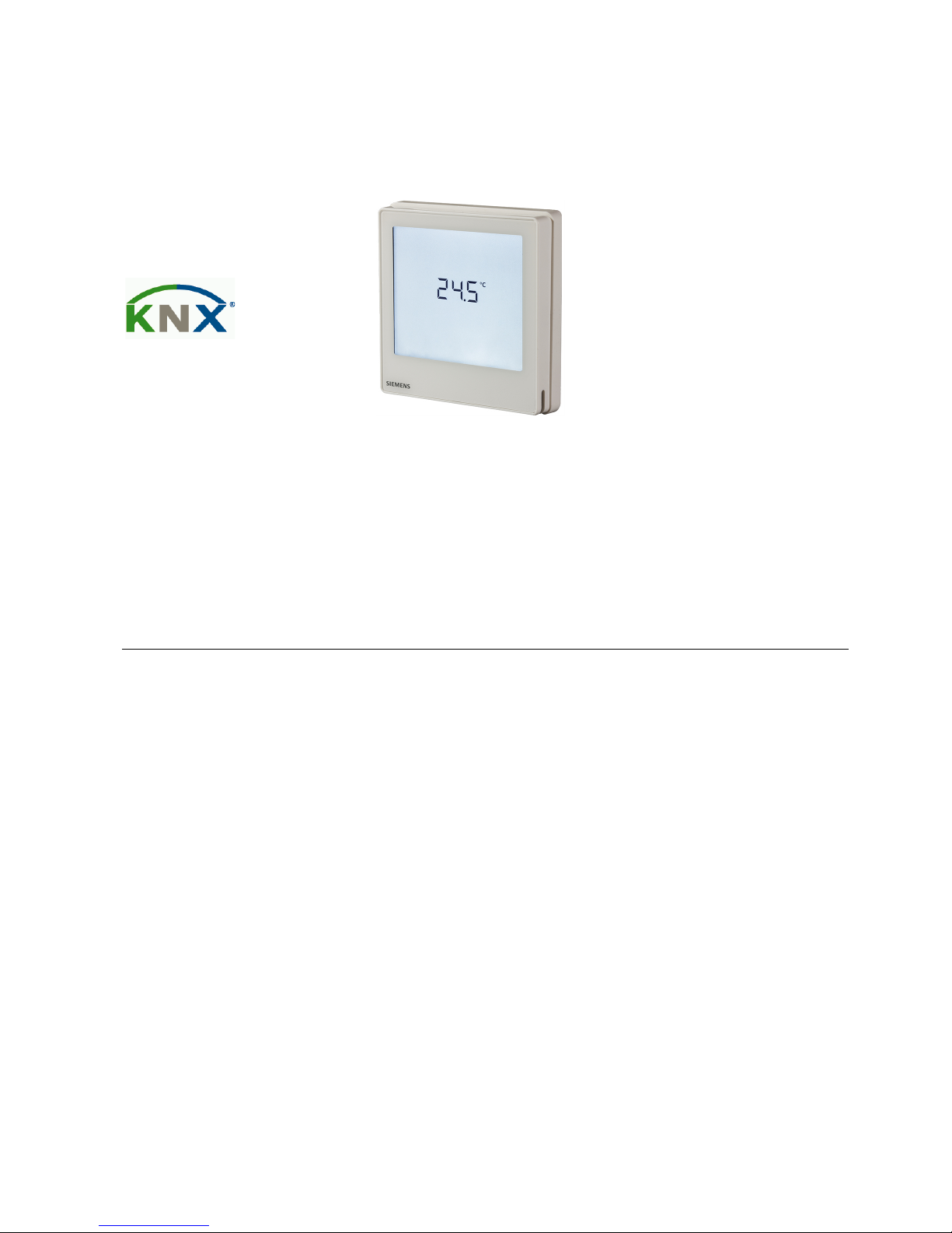
RDF800KN
RDF800KN/NF
Touch Screen Flush-mount Room
Thermostats with KNX
Communications
For 2-pipe, 2-pipe with electrical heater, and 4-pipe fan coil units
For universal applications
For use with compressors in DX type equipment
• KNX bus communications (S-mode and LTE mode)
• Large display with backlight
• 2P / PI / P control
• Outputs for ON/OFF or 3-position control
• Outputs for 3-speed or 1-speed fan
• 2 multifunctional inputs for keycard contact, external sensor, etc.
• Independent function for window contact and presence detector
• Operating modes: Comfort, Economy and Protection
• Automatic or manual fan speed control
• Automatic or manual heating / cooling changeover
• Minimum and maximum limitation of room temperature setpoint
• Control depending on the room or the return air temperature
• Adjustable commissioning and control parameters
• Commissioning with Synco ACS, ETS4 or via local HMI
• Interoperation into Synco 700
• Integration into Desigo via group (ETS4) or via individual addressing
• Integration into third-party system via group addressing (ETS4)
• AC 230 V operating voltage
• RDF800KN: Mounting on round box, with min 60 mm diameter or recessed
square 86 mm box with 60.3 mm fixing centers and min 40 mm depth
• RDF800KN/NF: Mounting on recessed square 86 mm box with 60.3 mm
fixing centers and min 40 mm depth, requires additional mounting frame
Page 2

2 / 20
Siemens RDF800KN… CB1N3174en
Building Technologies Touch Screen Flush-mount Room Thermostats with KNX Communications 2014-09-10
Use
Room temperature control (heating or cooling) in individual rooms and zones by
means of:
• 2-pipe fan coil units
• 2-pipe fan coil units with electrical heater
• 4-pipe fan coil units
• Chilled /heated ceiling
• Chilled /heated ceiling and electrical heater
• Chilled ceiling and radiator / under floor heating
• Compressors in DX-type equipment
• Compressors in DX-type equipment with electrical heater
The RDF800KN... controls:
• One single or 3-speed fan
• One or two ON/OFF valve actuators
• One ON/OFF valve actuator and one 1-stage electrical heater
• One 3-position valve actuator
• One 1-stage compressor in DX-type equipment, or one 1-stage compressor with
electrical heater
Used in systems with:
• Heating or cooling mode
• Automatic heating/cooling changeover
• Manual heating/cooling changeover
• Heating and cooling mode (such as 4-pipe system)
The room thermostats are delivered with a fixed set of applications. The relevant
application is selected and activated during commissioning using one of the
following tools:
• Synco ACS
• ETS4
• Local DIP switch and HMI
Functions
• Room temperature control via built-in temperature sensor or external room
temperature / return air temperature sensor
• Changeover between heating and cooling mode (automatically via local sensor
or bus, or manually)
• Selection of applications via DIP switches or commissioning tool
• Selection of operating mode via touch screen
• Temporary Comfort mode extension
• 1- or 3-speed fan control (automatically or manually)
• Display of current room temperature or setpoint in °C and/or °F
• Minimum and maximum limitation of room temperature setpoint
• Keylock function: unlock, total lock and setpoint
• 2 multifunctional inputs, freely selectable for:
− Window contact
− Presence detector
− External room temperature or return air temperature sensor
− Fault input
− Monitor input for temperature sensor or switch state
− Sensor for automatic heating / cooling changeover (RDF…)
− Dew point sensor (RDF…)
− Electric heater enable (RDF…)
• Advanced fan control function, such as: fan kick, fan start delay, and selectable
fan operation (enable, disable or depending on heating or cooling mode)
Page 3
3 / 20
Siemens RDF800KN… CB1N3174en
Building Technologies Touch Screen Flush-mount Room Thermostats with KNX Communications 2014-09-10
• Purge function together with 2-port valve in a 2-pipe changeover system
• Reminder to clean fan filters (adjust with P62)
• Floor heating temperature limitation
• Reload factory settings for commissioning and control parameters
• Wizard function for easy commissioning via HMI
• KNX bus (terminals CE+ and CE-) for communication with Synco or KNX
compatible devices
• Display of time of day via KNX bus
• Display of outdoor temperature via KNX bus on INFO page
• Time scheduling and central control of setpoints via KNX bus
• With a Synco RMx7xx controller, the energy demand signal of the thermostat is
used to optimize energy supply
Applications
The thermostats support the following applications, which can be configured using
the DIP switches on the inner side of the thermostat's front panel or a
commissioning tool.
All DIP switches need to be set to OFF (factory setting) to select an application via
commissioning tool.
Remote configuration, via commissioning tool (factory
setting)
• Synco ACS
• ETS4
DIP switches
Remote configuration
Page 4
4 / 20
Siemens RDF800KN… CB1N3174en
Building Technologies Touch Screen Flush-mount Room Thermostats with KNX Communications 2014-09-10
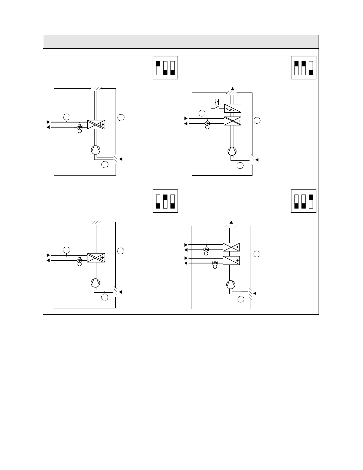
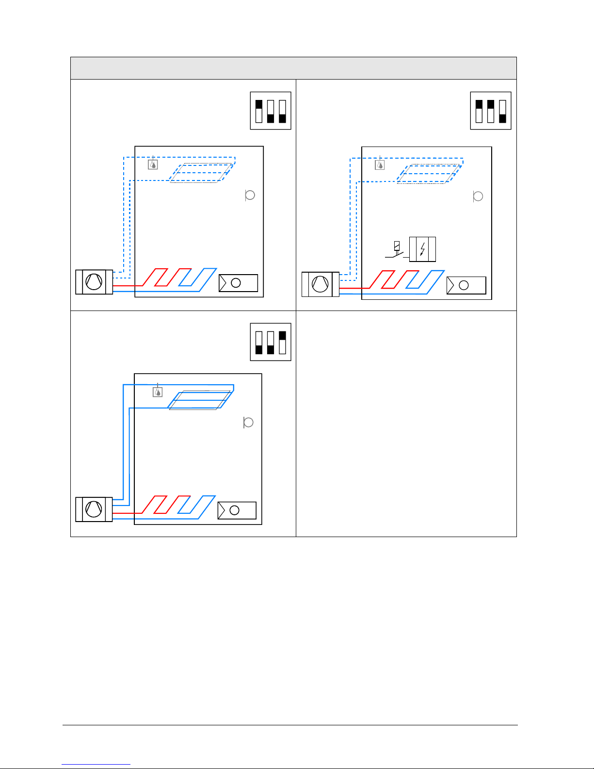
Applications for fan coil systems
Application and output signal, DIP switches, diagram
• 2-pipe fan coil unit ON/OFF
(heating or cooling)
1ON2 3
• 2-pipe fan coil unit with el. heater
(heating or cooling) ON/OFF
1
ON
2 3
3076D20
(B1)
M1
V1
T
B2
T
T
(B1)
V1
M1
3171D21
T
B2
E1
T
(B1)
T
(B1)
• 2-pipe fan coil unit 3-position
(heating or cooling)
1
ON
2 3
• 4-pipe fan coil unit ON/OFF
(heating and cooling)
1
ON
2
3
30
76D2
0
(B1)
M1
V1
T
B2
T
T
(B1)
T
V2
V1
M1
3076D22
(B1)
T
(B1)
V1 Heating or heating / cooling valve actuator
B1 Return air temperature sensor or external room
temperature sensor (optional)
V2 Cooling valve actuator
B2 Changeover sensor (optional)
E1 Electric heater
M1 3- or 1-speed fan
Page 5
5 / 20
Siemens RDF800KN… CB1N3174en
Building Technologies Touch Screen Flush-mount Room Thermostats with KNX Communications 2014-09-10
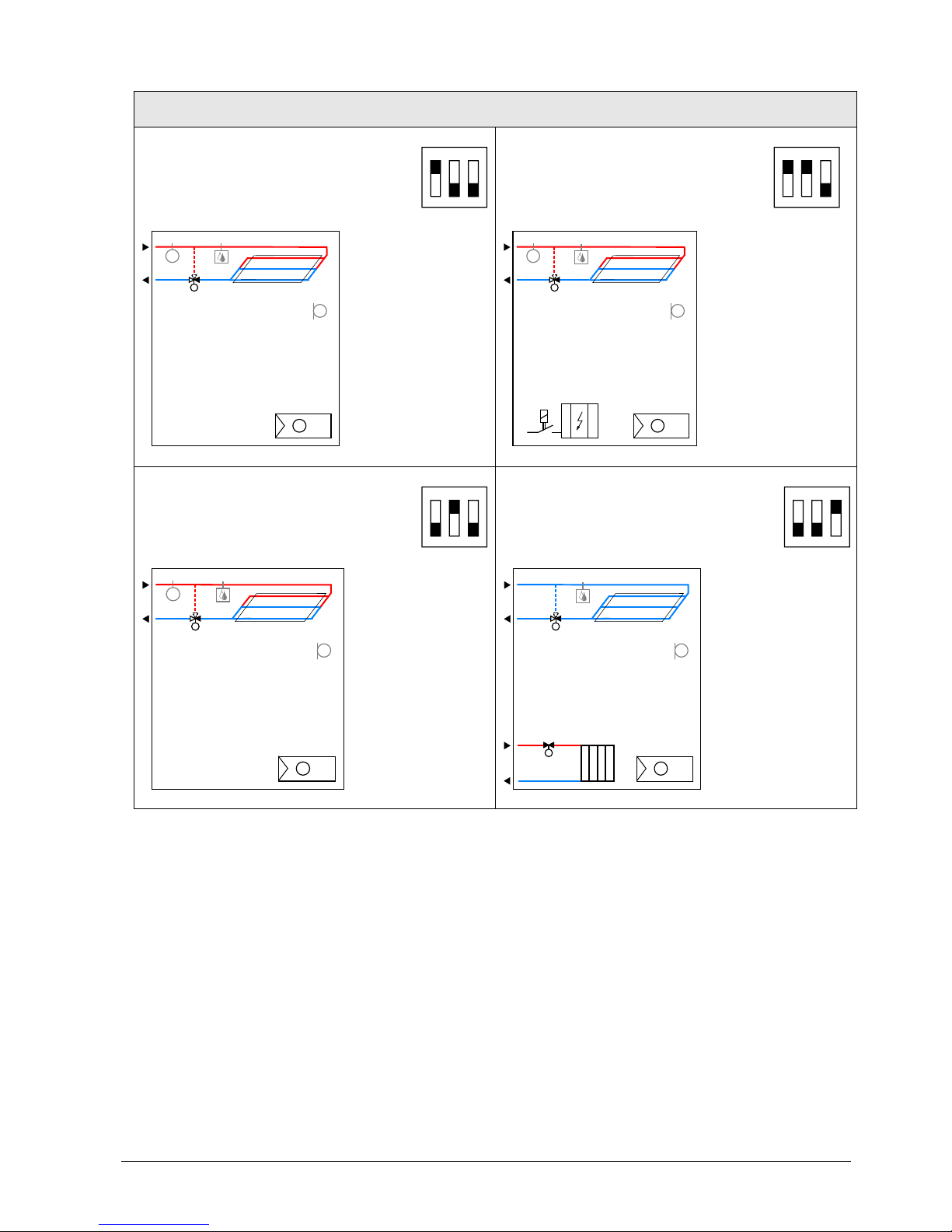
Applications for Universal systems
Application and output signal, DIP switches, diagram
• Chilled / heated ceiling ON/OFF
(heating or cooling)
1
ON
2
3
• Chilled / heated ceiling with electric
heater
(heating or cooling) ON/OFF
1
ON
2 3
3191S11
N1
T
B1
T
B2
T
D3
V1
3191S12
N1
T
E1
B1
T
B2
T
D3
V1
• Chilled / heated ceiling 3-position
(heating or cooling)
1ON2 3
• Chilled ceiling and radiator ON/OFF
(heating and cooling)
1
ON
2
3
3191S11
N1T
B1
T
B2
T
D3
V1
3191S13
N1T
B1
T
D3
V2
V1
V1 Heating or heating / cooling valve actuator
B1 Return air temperature sensor or external room
temperature sensor (optional)
V2 Cooling valve actuator
B2 Changeover sensor (optional)
E1 Electric heater
D3 Dewpoint sensor
Page 6
6 / 20
Siemens RDF800KN… CB1N3174en
Building Technologies Touch Screen Flush-mount Room Thermostats with KNX Communications 2014-09-10
Applications for heat pump systems
Application and output signal, DIP switches, diagram
• 1-stage compressor ON/OFF
(heating or cooling)
1ON2 3
• 1-stage compressor with electric
heater
(heating or cooling) ON/OFF
1
ON
2 3
3181S31
N1
T
B1
T
D3
3181S32
N1T
E1
B1
T
D3
• 1-stage compressor ON/OFF
(heating and cooling)
1ON2 3
3181S35
N1
T
B1
T
D3
N1 Thermostat
Terminal Y1: Heating (H&C) or Heating/Cooling
Terminal Y2: Cooling (H&C)
B1 Return air temperature sensor or external room
temperature sensor (optional)
E1 Electric heater
D3 Dewpoint sensor
Page 7

7 / 20
Siemens RDF800KN… CB1N3174en
Building Technologies Touch Screen Flush-mount Room Thermostats with KNX Communications 2014-09-10
Type summary
Product no. Stock no.
Operating
voltage
Control outputs
Suitable for
3-pos
ON/OFF
DC 0..10 V
RDF800KN
S55770-T350
AC 230 V
1 1)
2 1)
--
Round conduit box
RDF800KN/NF 2)
S55770-T335
AC 230 V
1 1) 2 1)
--
Square conduit box
2)
1)
Selectable: ON/OFF or 3-position
2)
Mounting frames are not included and must be ordered separately. See
“Accessories”
Ordering
• When ordering, indicate the product number, SSN and name.
For example: RDF800KN/NF (S55770-T335) room thermostat
RDF800KN (S55770-T350) room thermostat
• A mounting frame must be ordered for RDF800KN/NF installation
(See “Accessories”).
• Order valve actuators separately.
Equipment combinations
Type of unit
Product no.
Data sheet
Cable temperature sensor or
changeover sensor, cable length
2.5 m
NTC (3 kΩ at 25 °C)
QAH11.1
1840
Room temperature sensor
NTC (3 kΩ at 25 °C)
QAA32
1747
Cable temperature sensor,
cable length 4 m
NTC (3 kΩ at 25 °C)
QAP1030/UFH
1854
Condensation / Dew point monitor
QXA2601 /
QXA2602 /
QXA2603 /
AQX2604
3302
Electromotoric ON/OFF actuator
SFA21...
4863
Electromotoric ON/OFF valve and
actuator (only available in AP, UAE,
SA and IN)
MVI…/MXI…
4867
Zone valve actuators (only available
in AP, UAE, SA and IN)
SUA…
4832
Thermal actuator (for radiator valve)
STA23...
4884
Thermal actuator
(for small valves 2.5 mm)
STP23...
4884
ON/OFF actuators
Page 8

8 / 20
Siemens RDF800KN… CB1N3174en
Building Technologies Touch Screen Flush-mount Room Thermostats with KNX Communications 2014-09-10
Type of unit
Product no.
Data sheet
Electrical actuator, 3-position
(for radiator valve)
SSA31...
4893
Electrical actuator, 3-position
(for small valve 2.5 mm)
SSP31…
4864
Electrical actuator, 3-position
(for small valve 5.5 mm)
SSB31...
4891
Electrical actuator, 3-position
(for 2- and 3-port valves / V…P45)
SSC31…
4895
Electrical actuator, 3-position
(for small valve 5.5 mm)
SSD31...
4861
Electromotoric actuator, 3-position
(for small valves 5.5 mm)
SQS35…
4573
For the maximal number of actuators in parallel, refer to information in the data
sheets of the selected actuators and to this list, depending on which value is lower:
• Parallel operation of max 6 SS… actuators (3-pos) is possible.
• Parallel operation of max 10 ON/OFF actuators is possible.
• Parallel operation of SQS35 is not possible.
Accessories
Designation Product no. / SSN
Data
sheet
Changeover mounting kit
(50 pcs / package)
ARG86.3
N3009
Plastic mounting spacer for flush
mounted thermostats RDF800KN for
increasing the headroom in the conduit
box by 10mm
ARG70.3
N3009
Conduit box for RDF800KN
ARG71 /
S55770-T137
N3009
Single mounting frame *), Ivory White
(for RDF800KN/NF only)
ARG800.1 /
S55770-T370
--
KNX Power supply 160 mA
5WG1 125-1AB02
--
KNX Power supply 320 mA
5WG1 125-1AB12
--
KNX Power supply 640 mA
5WG1 125-1AB22
--
*)
See the dimensions of mounting frame on page 19.
3-position actuators
Note:
Page 9

9 / 20
Siemens RDF800KN… CB1N3174en
Building Technologies Touch Screen Flush-mount Room Thermostats with KNX Communications 2014-09-10
Mechanical design
The thermostats consist of the following parts:
• Front panel with electronics, operating elements and built-in room temperature
sensor.
• Mounting base with power electronics.
• Mounting frame is an additional part to complete the installation for
RDF800KN/NF.
The rear of the mounting base contains the screw terminals.
Slide the front panel in the mounting base and snap on.
Operation and
settings
Display
STATUS
and
OPERATION of the
thermostat
INFORMATION
1st Line:
temperature, values
of parameters
2nd Line: parameter
numbers, time clock
ADJUSTMENT for temperature setpoint, fan speed, operating
modes and settings (for example, Ala
rm, INFO, etc.)
SELECTION of
available INFO and
operating modes
Status symbols:
Key lock
Manual override
Alarm / Service reminder
Cooling active
Scheduler via bus
Heating active
FAN ACTIVE
Auxiliary heat active
Selection symbols:
Indoor temperature
Comfort mode
Outdoor temperature
Economy mode
Protection mode
Operational icons:
+
Increment, decrement OR selection
Selection OR move to next items
Temperature OR parameter values, and etc.
Time clock (12 / 24 hour), parameter number
OR password, and etc.
Setpoint mode (temperature only)
Fan mode OR fan speed mode
Operating mode
Setting mode
Page 10

10 / 20
Siemens RDF800KN… CB1N3174en
Building Technologies Touch Screen Flush-mount Room Thermostats with KNX Communications 2014-09-10
Engineering notes
See the "Reference documentation", page 15, for information on how to engineer
the KNX bus (topology, bus repeaters, etc.) and how to select and dimension
connecting cables for supply voltage and field devices.
Mounting and installation
Mount the room thermostat on a conduit box. Do not mount on a wall in niches or
between bookshelves, behind curtains, above or near heat sources, or exposed to
direct solar radiation. Mount about 1.5 m above the floor.
Mounting / Dismounting
• Do not apply excessive force on screws! The deformation of the mounting
frame may lead to improper connections and operation of the unit.
• Mount the room thermostat on a clean, dry indoor place without direct airflow
from a heating / cooling device, and not expose to drips or splashes water.
• For RDF800KN only, in case of limited space in the conduit box, use the
mounting spacer ARG70.3 to increase the headroom by 10mm.
• Before removing the front cover, disconnect the power supply.
Wiring
See the User Manual for the installation instructions enclosed with the thermostat.
• Comply with local regulations to wire, protection and earth the thermostat.
• The device has no internal fuse for supply lines to fan and actuators. To avoid
risk of fire and injury due to short-circuits, the AC 230 V mains supply line must
have a circuit breaker with a rated current of no more than 10 A.
• Properly size the cables to the thermostat, fan and valve actuators for
AC 230 V mains voltage.
• Use only valve actuators rated for AC 230 V.
• The wiring cross section used for power supply (L, N), fan / relays (Qx) and 230
V outputs (Yx - N) must be adapted to the preceding overload protection
elements (max 10A) under all circumstances. Comply under all circumstances
with local regulations.
• Cables of SELV inputs X1-M / X2-M: Use cables with min 230 V insulation, as
the conduit box carries AC 230 V mains voltage.
• Inputs X1-M or X2-M: Several switches (e.g. window contact) may be
connected in parallel. Consider overall maximum contact sensing current for
switch rating.
• KNX communication cables (input CE+ / CE-): Use cables with min 230 V
insulation, as the conduit box carries AC 230 V mains voltage.
• When a KNX bus power supply is connected on the line with communicating
thermostats and Synco controllers, the internal KNX power supply of the
Synco controllers must be switched off.
• No cables provided with a metal shield.
• Disconnect from supply before opening the cover.
Page 11

11 / 20
Siemens RDF800KN… CB1N3174en
Building Technologies Touch Screen Flush-mount Room Thermostats with KNX Communications 2014-09-10
Commissioning notes
Set DIP switches to select the desired application before power up:
1. For remote setup via commissioning tools, set all DIP switches to OFF (see
"Remote configuration" for more details);
2. For local setup, set DIP switches to select applications (refer to the following
table).
Commissioning
method
DIP switches LCD display Applications
Remote setup
APP
NONE
-
Local setup
APP
2P
2-pipe
APP
2PEH
2-pipe with electric heater
APP
4P
4-pipe
APP
2P3P
2-pipe with 3-position output
After DIP switch setting, complete the installation and power up the thermostat.
As soon as the application is changed, the thermostat reloads the factory setting
for all control parameters, except for KNX device and zone addresses!
After DIP switches are selected and the thermostat is powered up, the wizard
function guides users to configure the basic parameters for normal operation
according to the table below.
Touch / to advance / return to any parameter;
Touch + / - to change value.
LCD display
Parameter
Range
Factory setting
Control sequence
0: Heating only
1: Cooling only
2: Manual changeover
3: Auto changeover
4: Heating and Cooling
2-pipe = 1
4-pipe = 4
User operating
mode profile
1: comfort > protection
2: comfort > economy >
protection
1
Selection of
°C or °F
0: °C
1: °F
0
Standard display
0: Room temperature
1: Setpoint
0
Display info line
(2nd line of LCD
display)
0: --- (No display)
3: Time of day (12h) via bus
4: Time of day (24h) via bus
0
Fan Stage in
Deadzone
(Comfort mode)
0: Fan OFF
1: Fan speed 1 Heat / Cool
2: Fan speed 1 Cool only
0
Before power up
Note:
Wizard
Page 12

12 / 20
Siemens RDF800KN… CB1N3174en
Building Technologies Touch Screen Flush-mount Room Thermostats with KNX Communications 2014-09-10
LCD display
Parameter
Range
Factory setting
Functionality of X1
0: --- No function
1: Ext / Return Temp (AI)
2: H/C changeover (AI/DI)
3: Window open detect (DI)
4: Dew point sensor (DI)
5: Enable electr. Heater (DI)
6: Fault input (DI)
7: Monitor input (Digital)
8: Monitor input (Temp)
10: Presence detection (DI)
3
Functionality of X2 1
Operating action
of X1
Normal Open (NO)
Normal Close (NC)
Normal Open
(NO)
Operating action
of X2
- End of wizard -
If more details are required about parameters, refer to basic documentation P3174.
To re-load factory settings for all parameters, set parameter P71 to ON. Restart the
thermostat after reset, all LCD segments flash, indicating that the reset is correct.
3 seconds later, the thermostat is ready for commissioning by qualified HVAC staff.
The room thermostats are delivered with a fixed set of applications. Select and
activate the relevant application during commissioning using one of the following
tools:
− Local DIP switch and HMI
− Synco ACS
− ETS4
Connect the Synco ACS or ETS4 tools to the KNX bus cable at any point for
commissioning:
L
N Y1
Y2
X1 M X2
RDF800KN..
31
71
A
03
Q1 Q2 Q3
CE+ CE -
KNX
ETS4
RS232
Siemens
N148 /
UP146 /
UP152
ETS4 / ACS
Siemens
OCI700
or
OCI702...
ACS and ETS4 require an interface:
− RS232 KNX interface (such as Siemens N148 / UP146 / UP152)
− OCI700 USB - KNX interface
An external KNX bus power supply is required if an RDF800KN... is connected
directly to a tool (ACS or ETS4) via KNX interface.
Reset
Applications
Connect tool
Note:
Page 13

13 / 20
Siemens RDF800KN… CB1N3174en
Building Technologies Touch Screen Flush-mount Room Thermostats with KNX Communications 2014-09-10
The thermostat's control parameters can be set to ensure optimum performance of
the entire system (refer to basic documentation P3174).
The parameters can be adjusted using
− Local HMI
− Synco ACS
− ETS4
For commissioning via local HMI, refer to user manual B3174... for setting the
passwords.
• The control sequence may need to be set via parameter P01 depending on the
application. The factory setting for the 2-pipe application is "Cooling only"; and
"Heating and Cooling" for the 4-pipe application.
• When the thermostat is used with a compressor, adjust the minimum output on-
time (parameter P48) and off-time (parameter P49) for Y1 / Y2 to avoid
damaging the compressor or shortening its life due to frequent switching.
• Recalibrate the temperature sensor if the room temperature displayed on the
thermostat does not match the room temperature measured (after min. 1 hour of
operation). To do this, change parameter P05.
• We recommend to review the setpoints and setpoint ranges (parameters
P08…P12) and change them as needed to achieve maximum comfort and save
energy.
The programming mode helps identify the thermostat in the KNX network during
commissioning.
Touch and hold
for more than 5 seconds to activate programming mode, which
is indicated on the display with Pr09. Programming mode remains active until
thermostat identification is complete.
Assign device address (P81) via HMI, ACS or ETS4.
With device address set to 255, the communication is deactivated (no exchange of
process data).
Use ETS4 to assign the KNX group addresses of the RDF communication objects.
Each device has a unique KNX serial number inside the front panel. An additional
sticker with the same KNX serial number is enclosed in the packaging box. This
sticker is intended for installers for documentation purposes.
Disposal
The devices are considered electronics devices for disposal in terms of European
Directive 2012/19/EU and may not be disposed of as domestic waste.
• Dispose of the device via the channels provided for this purpose.
•
Comply with all local and currently applicable laws and regulations.
Control parameters
Control sequence
Compressor-based
application
Calibrate sensor
Setpoint and range
limitation
Programming mode
Assign KNX device
address
Assign KNX group
addresses
KNX serial number
Page 14

14 / 20
Siemens RDF800KN… CB1N3174en
Building Technologies Touch Screen Flush-mount Room Thermostats with KNX Communications 2014-09-10
Technical data
Power supply
Rated voltage
AC 230 V
Overvoltage category
III
Frequency
50/60 Hz
Power consumption
Max. 6.0 VA / 2.1 W
Caution
No internal fuse!
External preliminary protection with max C 10 A circuit breaker required in all cases.
Outputs Fan control Q1, Q2, Q3-N
Rating min, max resistive (inductive)
AC 230 V
Min. 5 mA, Max. 5(2) A
Fans must NOT be connected in parallel!
Connect one fan directly, for additional fans, one
relay for each speed.
Control output Y1-N / Y2-N (NO)
Rating Min, Max resistive (inductive)
Max. total load current through terminal "L" (Qx+Yx)
AC 230 V
Min. 5 mA, Max. 5(2) A
Max. 7 A
Caution
No internal fuse!
External preliminary protection with max C 10 A circuit breakers in the supply line
required in all cases.
Inputs Multifunctional input X1-M / X2-M
Temperature sensor input:
Type
Temperature range
Cable length
Digital input:
Operating action
Contact sensing
Parallel connection of several thermostats for
one switch
Insulation against mains voltage (SELV)
See “Equipment combinations”
0...49 °C
Max. 80 m
Selectable (NO / NC)
SELV DC 0...5 V / Max. 5 mA
Max. 20 thermostats per
switch
4 kV, reinforced insulation
Function of inputs:
External temperature sensor, heating/cooling
changeover sensor, window contact, presence
detection, dewpoint monitor contact, enable
electrical heater contact, fault contact, monitoring
input
Selectable
X1: P38
X2: P40
KNX bus
Interface type
KNX, TP1-64
(electrically isolated)
Bus current
5 mA
Bus topology: See KNX manual (see “Reference documentation”)
Operational data
Switching differential, adjustable
Heating mode (P30)
Cooling mode (P31)
2 K (0.5...6K)
1 K (0.5...6K)
Setpoint setting and range
Comfort (P08)
Economy (P11-P12)
Protection (P65-P66)
21 °C (5...40 °C)
15 °C / 30°C (OFF, 5...40 °C)
8 °C / OFF (OFF, 5...40 °C)
Multifunctional input X1/X2
Input X1 default value (P38)
Input X2 default value (P40)
Selectable 0...8, 10
3 (Window contact)
1 (External temperature
sensor)
STOP
Note!
Page 15

15 / 20
Siemens RDF800KN… CB1N3174en
Building Technologies Touch Screen Flush-mount Room Thermostats with KNX Communications 2014-09-10
Built-in room temperature sensor
Measuring range
Accuracy at 25 °C
Temperature calibration range
0…49 °C
< ± 0.5 K
± 3.0 K
Settings and display resolution
Setpoints
Current temperature value displayed
0.5 °C
0.5 °C
Environmental
conditions
Operation
Climatic conditions
Temperature
Humidity
As per IEC 60721-3-3
Class 3K5
0...50 °C
<95 % r.h.
Transport
Climatic conditions
Temperature
Humidity
Mechanical conditions
As per IEC 60721-3-2
Class 2K3
−25...65 °C
<95 % r.h.
Class 2M2
Storage
Climatic conditions
Temperature
Humidity
As per IEC 60721-3-1
Class 1K3
−25...65 °C
<95 % r.h.
Standards and
directives
EU Conformity (CE)
8000078258_xx*)
Electronic control type 2.B (micro-disconnection on
operation)
RCM conformity to EMC emission standard
AS/NZS 61000-6-3
Safety class
II as per EN 60730
Pollution class
Normal
Degree of protection of housing IP 30 as per EN 60529
Environmental
compatibility
The product environmental declaration E3174en contains data on environmentally
compatible product design and assessments (RoHS compliance, materials
composition, packaging, environmental benefit, disposal).
General Connection terminals Solid wires or prepared
stranded wires
1 x 0.4…1.5 mm
2
or
2 x for KNX cables/sensor
Minimal wiring cross section on
L, N, Q1, Q2, Q3, Y1, Y2
Min 1.5 mm2
Housing front color
Ivory White
Weight without / with packaging
0.155 kg / 0.255 kg
*)
The documents can be downloaded from http://siemens.com/bt/download.
Reference
documentation
Handbook for Home and Building Control - Basic Principles
(http://www.knx.org/knx-en/training/books-documentation/knx-association-books/index.php)
Synco
CE1P3127 Communication via the KNX bus for Synco 700, 900 and RXB/RXL
Basic documentation
Desigo CM1Y9775 Desigo RXB integration – S-mode
CM1Y9776 Desigo RXB / RXL integration – individual addressing
CM1Y9777 Third-party integration
CM1Y9778 Synco integration
CM1Y9779 Working with ETS
Page 16

16 / 20
Siemens RDF800KN… CB1N3174en
Building Technologies Touch Screen Flush-mount Room Thermostats with KNX Communications 2014-09-10
Connection terminals
L X1 M
N
Q1 Q2 Q3
Y1
SELV
Y2
X2
3171A01
CE+ CE
-
L, N Operating voltage AC 230 V
Q1 Control output "Fan speed 1 AC 230 V"
Q2 Control output "Fan speed 2 AC 230 V"
Q3 Control output "Fan speed 3 AC 230 V"
Y1,Y2 Control output "Valve" AC 230 V (N.O., for normally
closed valves), output for compressor or output for
electrical heater
X1, X2 Multifunctional input for temperature sensor (such as
QAH11.1) or potential-free switch
Factory setting:
– X1 = Window contact
– X2 = External sensor
(function can be selected via parameter P38 / P40)
M Measuring neutral for sensor and switch
CE+ KNX data +
CE- KNX data -
Connection diagrams
Application
N1 Room thermostat RDF800KN...
M1 1- or 3-speed fan
V1 Valve actuator, 2- or 3-position
V1, V2 Valve actuator, 2-position
E1 Electric heater
C1, C2 1-stage compressor
S1, S2 Switch (keycard, window contact,
presence detector, etc.)
B1, B2 Temperature sensor (return air
temperature, external room
temperature, changeover sensor,
etc.)
CE+ KNX data +
CE- KNX data –
2-pipe / heating or
cooling – ON/OFF
2-pipe, / heating or
cooling – 3-position
− Y1 = Open
−
Y2 = Close
2-pipe and el.
heater/
Heating or cooling
and el. heater
4-pipe /
Heating and radiator
− V1 = Heating
−
V2 = Cooling
1-stage compressor
− C1 = Heating
and / or
−
C2 = Cooling
1-stage compressor
and electric heater
L
N
10 A
L
N
Y1
Y2
AC 230 V
X1MX2
N1
M1
V1
5(2)A
Max .
5(2)A
Max .
B2
S2
B1
S1
3
171
A12
Q1 Q2 Q3
I II III
CE+ CE-
KNX
V1
5(2)A
Max .
E1
5(2)A
Max .
5(2)A
Max .
V1
C1
5(2)A
Max .
V1
5(2)A
Max .
V2
5(2)A
Max .
C1
5(2)A
E1
5(2)A
C2
5(2)A
Max .
Page 17

17 / 20
Siemens RDF800KN… CB1N3174en
Building Technologies Touch Screen Flush-mount Room Thermostats with KNX Communications 2014-09-10
Dimensions (mm)
RDF800KN/NF
for square conduit
boxes only
Page 18

18 / 20
Siemens RDF800KN… CB1N3174en
Building Technologies Touch Screen Flush-mount Room Thermostats with KNX Communications 2014-09-10
RDF800KN
for round
conduit boxes
Page 19

19 / 20
Siemens RDF800KN… CB1N3174en
Building Technologies Touch Screen Flush-mount Room Thermostats with KNX Communications 2014-09-10
ARG800.1 single
mounting frame for
RDF800KN/NF
Page 20

20 / 20
Siemens RDF800KN… CB1N3174en
Building Technologies Touch Screen Flush-mount Room Thermostats with KNX Communications 2014-09-10
2014 Siemens Switzerland Ltd Subject to change
 Loading...