

Page 1
CE1N3076en
2018-12-27
Building Technologies
s
3
076
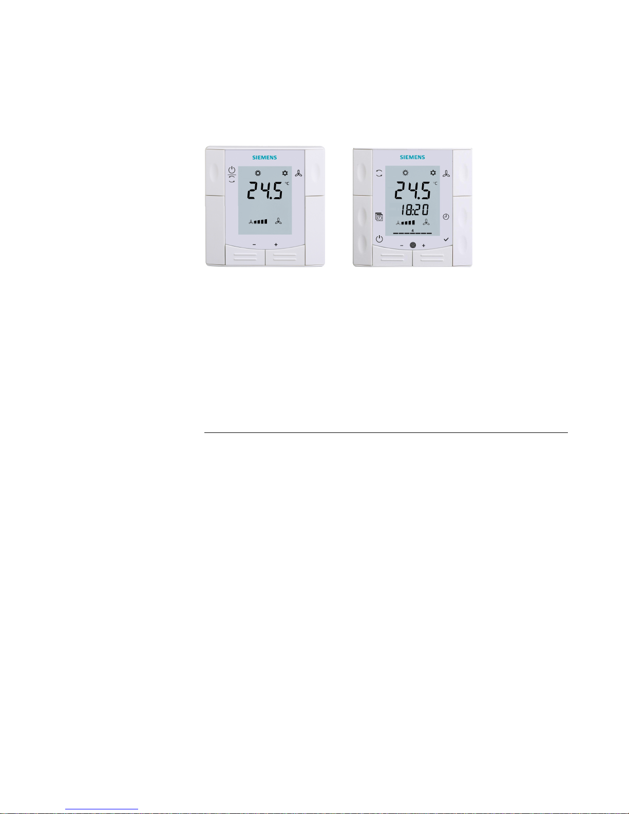
RDF300, RDF300.02, RDF340 RDF400.01
RDF600 RDF600T
Flush-mounted
room thermostats
RDF300…
RDF340
RDF400…
RDF600...
for 2-pipe, 2-pipe with el. heater and 4-pipe fan coil units
for use with compressors in DX type equipment
· RDF300 / RDF400 / RDF600/RDF600T:
AC 230 V operating voltage, on/off or 3-position control outputs
· RDF340…:AC 24 V, operating voltage, DC 0…10 V control outputs
· Output for 3-speed or 1-speed fan
· 2 multifunctional inputs for keycard contact, external sensor, etc.
· Operating modes: Comfort, Economy and Protection
· Automatic or manual fan speed control
· Automatic or manual heating/cooling changeover
· Adjustable commissioning and control parameters
· Minimum and maximum setpoint limitation
· User and parameter settings can be retained o r restored with power loss
Additional features
· Backlit LCD (RDF300.02, RDF400.01, RDF600, RDF600T)
· Infrared remote control receiver (RDF400.01, RDF600T)
· Auto Timer mode with 8 programmable timers (RDF400.01, RDF600T)
Type of mounting / suitable conduit boxes
· RDF600... for round CEE box, with min 60 mm diameter, min 40 mm depth
· RDF3… / RDF400... for recessed square box with 60.3 mm fixing centers
Page 2

2/14
Siemens RDF300…/RDF340 / RDF400… / RDF 600... Flush-mounted Room thermostats CE1N3076en
Building Technologies 2018-12-27
Use
To control the room temperature in individual rooms and zones that are:
· Heated or cooled with 2-pipe fan coil units
· Heated or cooled with 2-pipe fan coil units with electrical heater
· Heated and cooled with 4-pipe fan coil units
· Heated or cooled with compressor in DX type equipment
· Heated or cooled with compressor in DX type equipment with electrical heater
· Heated and cooled with compressor in DX type equipment
The RDF300… / RDF400… / RDF600... control:
· One 1- or 3-speed fan
· One or 2 on/off valve actuators
· One on/off valve actuator and one 1-stage electrical heater
· One 3-position valve actuator
· One 1-stage compressor in DX type equipment or one 1-stage compressor with
electrical heater
The RDF340… controls:
· One 1- or 3-speed fan
· One or 2 DC 0…10 V valve actuators
· One DC 0…10 V valve actuator and one modulating electrical heater (DC 0…10 V)
Used in systems with:
· Heating or cooling mode
· Automatic heating/cooling changeover
· Manual heating/cooling changeover
· Heating and cooling mode (e.g. 4-pipe system)
Functions
· Maintain room temperature via built-in temperature sensor or external room
temperature / return air temperature sensor
· Automatic or manual changeover between heating and cooling mode
· Select applications via DIP switches
· Select operating mode via the operating mode button on the thermostat
· 1- or 3-speed fan control (automatic or manual)
· Display current room temperature or setpoint in °C and/or °F
· Minimum and maximum setpoint limitation
· Key lock (automatic and manual)
· 2 multifunctional inputs, freely selectable for:
– Operating mode switchover contact (key card)
– Automatic heating/cooling changeover sensor
– External room temperature or return air temperature sensor
– Dewpoint sensor
– Electrical heater enable
– Alarm input
· Advanced fan control function, i.e. fan kick, fan start, selectable fan operation
(enable, disable or depending on heating or cooling mode)
· Purge function together with 2-port valve in a 2-pipe changeover system
· Reminder to clean filters
· Floor heating temperature limit
· Reload factory settings for commissioning and control parameters
· 7-day time program: 8 programmable timers to switch over between Comfort and
Economy mode (RDF400.01 / RDF600T)
· Backlit LCD (RDF300.02 / RDF400.01 / RDF600 / RDF600T)
· Optional infrared remote control ( RDF400.01 / RDF600T)
Applications
Page 3
3/14
Siemens RDF300…/RDF340 / RDF400… / RDF 600... Flush-mounted Room thermostats CE1N3076en
Building Technologies 2018-12-27
Applications
The thermostat supports the following applications, which can be configured by DIP
switches on the inner side of the thermostat’s front. Depending on the type, on/off or
modulating control outputs are available.
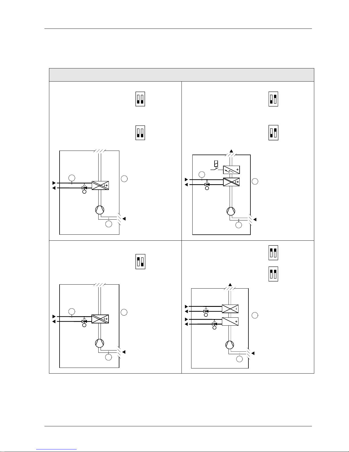
Applications for fan coil systems
Application and output signal, DIP switches, diagram
· 2-pipe fan coil unit
ON/OFF
(heat ing or cooling)
ON
1 2
RDF300...
RDF400...
RDF600...
· 2-pipe fan coil unit ON/OFF
(heat ing or cooling)
with electrical heater
ON
1 2
RDF300...
RDF400...
RDF600...
· 2-pipe fan coil unit
modulating, DC 0…10 V
(heat ing or cooling)
ON
1 2
RDF340
· 2-pipe fan coil unit
modulating, DC 0…10 V
(heat ing or cooling)
with electrical heater
ON
1 2
RDF340
3076D20
(B1)
M1
V1
T
B2
T
T
(B1)
V1
M1
3171D21
T
B2
E1
T
(B1)
T
(B1)
· 2-pipe fan coil unit
modulating, 3-position
(heat ing or cooling)
ON
1 2
RDF300...
RDF400...
RDF600...
· 4-pipe fan coil unit ON/OFF
(heat ing and cooling)
ON
1 2
RDF300...
RDF400...
RDF600...
ON
1 2
RDF340
3076D20
(B1)
M1
V1
T
B2
T
T
(B1)
T
V2
V1
M1
3076D22
(B1)
T
(B1)
V1 Heating or h eating/cooling valve actuator M1 3-speed or single-speed fan
V2 Cooling val ve actuator B1 Return air temperatur e sensor or
external room temperature sensor (optional)
E1 Electric al heater B2 Changeover sens or (optional)
Page 4
4/14
Siemens RDF300…/RDF340 / RDF400… / RDF 600... Flush-mounted Room thermostats CE1N3076en
Building Technologies 2018-12-27
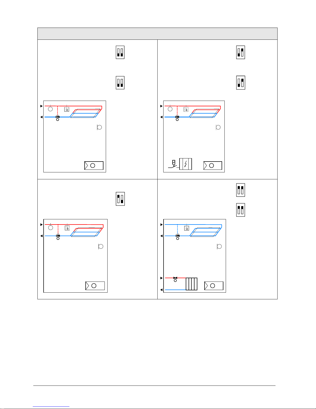
Applications for Universal systems
Application and output signal, DIP switches, diagram
· Chilled / heated ceiling
ON/OFF
(heat ing or cooling)
ON
1 2
RDF300...
RDF400...
RDF600...
· Chilled / heated ceiling
ON/OFF (heating or cooling)
with electrical heater
ON
1 2
RDF300...
RDF400...
RDF600...
· Chilled / heated ceiling
modulating, DC 0…10 V
(heat ing or cooling)
ON
1 2
RDF340
· Chilled / heated ceiling
modulating, DC 0…10 V
(heat ing or cooling)
with electrical heater
ON
1 2
RDF340
3
191S1
1
N1T
B1
T
B2
T
D3
V1
3
191S1
2
N1T
E1
B1
T
B2
T
D3
V1
· Chilled / heated ceiling
modulating, 3-position
(heat ing or cooling)
ON
1 2
RDF300...
RDF400...
RDF600...
· Chilled ceiling and radiator
ON/OFF
(heat ing and cooling)
ON
1 2
RDF300...
RDF400...
RDF600...
ON
1 2
RDF340
3191S11
N1T
B1
T
B2
T
D3
V1
3191S13
N1T
B1
T
D3
V2
V1
V1 Heating or heating / cooling valve actuator B1 Return air temperature sensor or external room
temperature sensor (optional)
V2 Cooling val ve actuator B2 Changeover sensor (optional)
E1 Electrical heater D3 Dewpoint sensor
Page 5
5/14
Siemens RDF300…/RDF340 / RDF400… / RDF 600... Flush-mounted Room thermostats CE1N3076en
Building Technologies 2018-12-27
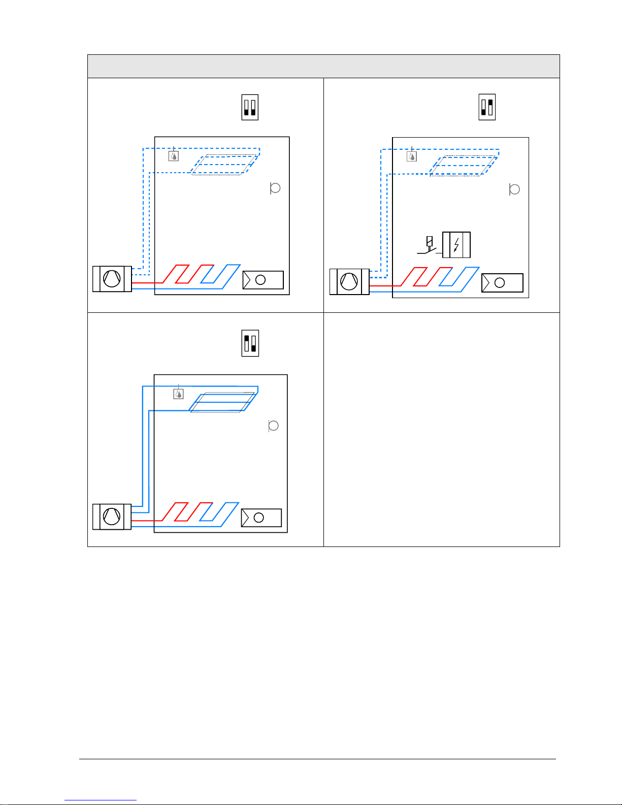
Applications for heat pump systems
Application and output signal, DIP switches, diagram
· 1-stage compressor ON/OFF
(heat ing or cooling)
ON
1 2
RDF300...
RDF400...
RDF600...
· 1-stage compressor ON/OFF
(heat ing or cooling)
with electrical heater
ON
1 2
RDF300...
RDF400...
RDF600...
3181S31
N1
T
B1
T
D3
3181S32
N1T
E1
B1
T
D3
· 1-stage compressor ON/OFF
(heat ing and cooling)
ON
1 2
RDF300...
RDF400...
RDF600...
3181S35
N1
T
B1
T
D3
N1 Thermostat
Terminal Y10/Y11: Heating (H&C) or Heating/Cooling
Terminal Y20/Y21: Cooling (H&C)
B1 Return air temperature sensor or external room
temperature sensor (optional)
E1 Electrical heater D3 Dewpoint sensor
Page 6

6/14
Siemens RDF300…/RDF340 / RDF400… / RDF 600... Flush-mounted Room thermostats CE1N3076en
Building Technologies 2018-12-27
Type summary
Product
number
Stock number Features
Operating
Voltage
Control outputs
Time
program
Backlit
LCD
Infrared
receiver1)Suitable
conduit
box
2)
on/off 3pt DC 0..10V
RDF300 RDF300 AC 230 V
ü ü
square
RDF300.02 RDF300.02 AC 230 V
ü ü ü
square
RDF400.01 RDF400.01 AC 230 V
ü ü ü ü ü
square
RDF340 RDF340 AC 24 V
ü
square
RDF600 S55770-T291 AC 230 V
ü ü ü
round
RDF600T S55770-T292 AC 230 V
ü ü ü ü ü
round
1) Infrared remote c ontrol is to be ordered as separat e item
2) Square conduit box e.g. ARG71 .
Round conduit box min 60 mm diameter and min 40 mm depth
Ordering
· When ordering, indicate both product number / SSN number and name:
E.g. RDF600 / S55770-T291 room thermostat
· Order the IRA211 (S55770-T166) infrared remote control separately (for
RDF400../RDF600...).
· Order valve actuators separately.
Equipment combinations
Designation Product no. Data Sheet
*)
Cable temperature sensor or
changeover sensor, cable length
2.5 m
NTC (3 kW at 25 °C)
QAH11.1 1840
Room temperature sensor
NTC (3 kW at 25 °C)
QAA32 1747
Cable temperature sensor,
cable length 4 m
NTC (3 kW at 25 °C)
QAP1030/UFH 1854
Condensation monitor QXA21.. A6V10741072
Electromotoric ON/OFF actuator SFA21... 4863
Electromotoric ON/OFF valve and
actuator (only available in AP, UAE,
SA and IN)
MVI…/MXI… A6V11251892
Zone valve actuators (only available
in AP, UAE, SA and IN)
SUA… 4832
Thermal actuator (for radiator valve) STA23... 4884
Thermal actuator
(for small valves 2.5 mm)
STP23... 4884
On / off actuators
Page 7

7/14
Siemens RDF300…/RDF340 / RDF400… / RDF 600... Flush-mounted Room thermostats CE1N3076en
Building Technologies 2018-12-27
Designation Product no. Data Sheet
*)
Electrical actuator, 3-position
(for radiator valve)
SSA31... 4893
Electrical actuator, 3-position
(for small valve 2.5 mm)
SSP31… 4864
Electrical actuator, 3-position
(for small valve 5.5 mm)
SSB31... 4891
Electrical actuator, 3-position
(for 2- and 3-port valves / V…P45)
SSC31… 4895
Electromotoric actuator, DC 0...10 V
(for valves 5.5 mm)
SAS61.. 4581
Electromotoric actuator, DC 0...10 V
(for valves 5.5 mm)
SAT61.. 4584
Electrical actuator, DC 0...10 V
(for radiator valves)
SSA61.. 4893
Electrical actuator, DC 0...10 V
(for 2- and 3-port valves/V…P45)
SSC61.. 4895
Electrical actuator, DC 0...10 V
(for small valves 2.5 mm)
SSP61.. 4864
Electrical actuator, DC 0...10 V
(for small valves 5.5 mm)
SSB61.. 4891
Electromotoric actuator, DC 0...10 V
(for valves 5.5 mm)
SAS61.. 4581
Electromotoric actuator, DC 0...10 V
(for valves 5.5 mm)
SAT61.. 4584
Electrothermal actuator,
AC 24 V, NC, DC 0…10 V, 1 m
STA63 4884
Electrothermal actuator,
AC 24 V, NO, DC 0…10 V, 1 m
STP63 4884
*) The documents can be downloaded from http://siemens.com/bt/download.
Accessories
Designation Product no. Data Sheet
Changeover mounting kit (50 pcs/package) ARG86.3 N3009
Plastic mounting spacer for flush-mounted
thermostats RDF3.. RDF400… for
increasing the headroom in the conduit box
by 10 mm
ARG70.3 N3009
Conduit box for flush-mounted thermostat
RDF3.. RDF400…
ARG71 /
S55770-T137
N3009
3-position actuators
DC 0…10 V actuators
Page 8

8/14
Siemens RDF300…/RDF340 / RDF400… / RDF 600... Flush-mounted Room thermostats CE1N3076en
Building Technologies 2018-12-27
Mechanical design
The thermostat consists of 2 parts:
· Front panel accommodating the electronics, operating elements and built-in room
temperature sensor.
· Mounting base with the power electronics.
The rear of the mounting base contains the screw terminals Slide the front panel in the
mounting base and snap on.
1. Operating mode selector / Protection
2. Change fan operation
3. Adjust setp oint and control parameters
1. Change operating mode selector
2. Change fan operation
3. Adjust setpoint, control parameters and time
of day
4. Auto Timer pr ogram
5. Protection
6. Set time of day and weekday
7. Confirm
8. Infrared receiver
1. Operating mode
Protection
AUTO
Auto Timer mode *
Comfort
Economy
2. Display room temperature, setpoints and
control parameters.
Symbol us ed to display the current room
temperature
3. Heating/c ooling mode
Cooling mode
Heating mode,
Electrical heater active
4. Fan mode
Auto fan active
Fan speed low, medium, high
5. Additional us er information (RDF3xx) or
current time of day (RDF400 / RDF600T)
6. Weekday 1..7 (1 = Monday/7 = Sunday)*
7. Key lock active
8. Condensation in room
(dewpoint sensor active)
9. Indic ate fault or reminder
* only on RDF400… / RDF600T
Operation and settings
RDF300…/RDF340…
RDF600
RDF400…
RDF600T
Display
2
1
3
21
5
8
6
3
4
7
1
2
3
4
5
6
9
7
8
Page 9

9/14
Siemens RDF300…/RDF340 / RDF400… / RDF 600... Flush-mounted Room thermostats CE1N3076en
Building Technologies 2018-12-27
Mounting and ins tallation
Mount the room thermostat on the conduit box. Do not mount on a wall in niches or
bookshelves, behind curtains, above or near heat sources, or exposed to direct solar
radiation. Mount about 1.5 m above the floor.
· Devices must be mounted on clean, dry indoor place without direct airflow from a
heating / cooling device, and not be exposed to dripping or splashing
· RDF3… / RDF400… : In case of limited space in the conduit box use the mounting
bracket ARG70.3 to increase the headroom by 10mm
· Before removing the front cover, disconnect the power supply.
See the mounting instructions enclosed with the thermostat:
M3076... for RDF3..., RDF4... ; M3063 for RDF600... .
· Wiring, protection and earthing must be installed in compliance with local
regulations.
Warning !
No internal line protection for supply lines to external consumers
(Q1, Q2, Q3, Yxx)
Risk of fire and injury due to short-circuits!
· Adapt the line diameters as per local regulations to the rated value of the installed
overcurrent protection device.
· Use only valve actuators rated for AC 230 V on RDF300… / RDF400… / RDF600..
· The AC 230 V mains supply line must have an external fuse or circuit breaker with a
rated current of no more than 10 A.
· Isolate the cables of SELV inputs X1-M/X2-M if the conduit box carries AC 230 V
mains voltage.
· Inputs X1-M or X2-M of different units (e.g. summer/winter switch) may be
connected in parallel with an external switch. Consider overall maximum contact
sensing current for switch rating.
· No metal conduits
· No cables provided with a metal sheath
· Disconnect from supply before opening the cover
Set the thermostat application via the DIP switches before snapping the front panel on
the mounting base.
After power is applied, the thermostat carries out a reset during which all LCD
segments flash indicating that the reset was correct. After the reset, which takes about
3 seconds, the thermostat is ready for commissioning by qualified HVAC staff.
The control parameters of the thermostat can be set to ensure optimum performance of
the entire system (see basic documentation P3076).
After powerfail the thermostat restarts in the same mode as before.
Mounting /
dismounting
Wiring
Commissioning
Note
Page 10

10/14
Siemens RDF300…/RDF340 / RDF400… / RDF 600... Flush-mounted Room thermostats CE1N3076en
Building Technologies 2018-12-27
· The control sequence may need to be set via parameter P01 depending on the
application. The factory setting for the 2-pipe application is “Cooling only”; and
“Heating and Cooling” for the 4-pipe application.
· When the thermostat is used with a compressor, the minimum output on-time
(parameter P48) and off-time (parameter P49) for Y11/Y21 must be adjusted to
avoid damaging the compressor and shortening its life.
· Recalibrate the temperature sensor if the room temperature displayed on the
thermostat does not match the room temperature measured (after min. 1 hour of
operation). To do this, change parameter P05.
We recommend to review the setpoints and setpoint ranges (parameters P08…P12)
and change them as needed to achieve maximum comfort and save energy.
Disposal
The device is considered electrical and electronic equipment for disposal in terms of the
applicable European Directive and may not be disposed of as domestic garbage.
· Dispose of the device through channels provided for this purpose.
· Comply with all local and currently applicable laws and regulations.
Technical data
Rated voltage RDF300… /400… / 600...
RDF340…
AC 230 V
SELV AC 24 V± 20 % or
AC 24 V class 2 (US)
Frequency 50/60 Hz
Power consumption RDF300... / RDF400.. RDF340…
RDF600…
Max. 8 VA
Max. 3.5 VA / 0.8 W
External supply line protection (EU)
Circuit breaker max. 10 A
Characteristic B, C, D
according to EN 60898
or
Power source with current
limitation of max. 10 A
No internal fuse
External preliminary protection with max. C 10 A circuit breaker in the supply line
r
equired under all circumstances
Fan control Q1, Q2, Q3- N
Rating
AC 230 V
5 mA...5(2) A
Control output Y11-N/Y21-N (N.O.)
Rating
AC 230 V
5 mA...5(2) A
Control output Y10-G0/Y20-G0
Resolution
Current
SELV DC 0…10 V
39 mV
Max. ± 1 mA
Max. total load current through terminal "L" (Qx + Yxx)
Max. 7 A
Multifunctional input X1-M/X2-M
Temperature sensor input:
Type
Temperature range
Cable length
Digital input:
Operating action
Contact sensing
Parallel connection of several thermostats
for one switch
Insulation against mains voltage (SELV)
NTC (3 kW at 25 °C)
0...49 °C
Max. 80 m
Selectable (N.O./N.C.)
SELV DC 0...5 V/max. 5 mA
Max. 20 thermostats per
switch
4 kV, reinforced insulation
Control sequence
Compressor-based
application
Calibrate sensor
Setpoint and range
limitation
Power supply
Outputs
Inputs
Page 11

11/14
Siemens RDF300…/RDF340 / RDF400… / RDF 600... Flush-mounted Room thermostats CE1N3076en
Building Technologies 2018-12-27
Funct ion input:
External temperature sensor, heating/cooling
changeover sensor, operating mode switchover
contact, dewpoint monitor contact, enable electrical
heater contact, alarm contact
Selectable
X1: P38
X2: P40
Switching differential, adjustable
Heating mode (P30)
Cooling mode (P31)
2 K (0.5...6K)
1 K (0.5...6K)
Setpoint setting and range
Comfort (P08)
Economy (P11-P12)
Protection (P65-P66)
21°C (5...40 °C)
15°C/30°C (OFF, 5...40 °C)
8°C/OFF (OFF, 5...40 °C)
Multifunctional input X1/X2
Input X1
Input X2
Selectable 0…6
3: (P38) operating mode
switchover
2: (P40) heating/cooling
changeover sensor
Built-in room temperature sensor
Measuring range
Accuracy at 25 °C
Temperature calibration range
0…49 °C
< ± 0.5 K
± 3.0 K
Settings and display resolution
Setpoints
Current temperature value displayed
0.5 °C
0.5 °C
Storage
Climatic conditions
As per IEC 60721-3-1
Class 1K3
Transport
Climatic conditions
As per IEC 60721-3-2
Class 2K3
Operation
Climatic conditions
As per IEC 60721-3-3
Class 3K5
1)
EU Conformity (CE)
CE1T3076_1
*)
CE1T3076xx_2
*)
CE1T3076xx_3
*)
RCM Conformity
CE1T3076_1en_C1
*)
CE1T3076xx_2en_C1
*)
CE1T3076xx_3en_C1
*)
Degree of protection of housing IP 30 to EN 60529
Protective class II as per EN 60730-1
Pollution class Normal
The product environmental declarations CE1E3076_1, CE1E3076_2, CE1E3076_3
*)
contain data on environmentally compatible product design and assessments (RoHS
compliance, materials composition, packaging, environmental benefit, disposal).
Connection terminals Solid wires or prepared
stranded wires
1 x 0.4…1.5 mm
2
Housing front color RAL 9003 white
Weight RDF3..., RDF4...
RDF600...
0.220 kg
0.150 kg
*) The documents can be downloaded from http://siemens.com/bt/download.
1) No condensation is allowed.
Operational data
Environmental
conditions
Standards and
directives
Environmental
compatibility
General
Page 12

12/14
Siemens RDF300…/RDF340 / RDF400… / RDF 600... Flush-mounted Room thermostats CE1N3076en
Building Technologies 2018-12-27
Connection terminals
L X1M
N
Q1 Q2 Q3
Y11N
SELV
Y21
X2
L, N Operating voltage AC 230 V
Q1 Control output “Fan speed 1 AC 230 V”
Q2 Control output “Fan speed 2 AC 230 V”
Q3 Control output “Fan speed 3 AC 230 V”
Y11,Y21 Control output “Valve” AC 230 V (N.O.,
for normally closed valves), output for
compressor or output for electrical heater
X1, X2 Multifuncti onal input for temperature
sensor (e.g. QAH11.1) or potential-free
switch
M Measuring neutral for sensor and switch
G X1M
G0
Q1 Q2 Q3
Y10 G0
SELV
Y20
X2
L
G, G0 Operating voltage thermostat AC 24 V
L Operating voltage for fan AC 230 V
Q1 Control output “Fan speed 1 AC 230 V”
Q2 Control output “Fan speed 2 AC 230 V”
Q3 Control output “Fan speed 3 AC 230 V”
Y10,Y20 Control output for DC 0…10 V actuator
X1, X2 Multifuncti onal input for temperature
sensor (e.g. QAH11.1) or switch
M Measuring neutral for sensor and swit ch
Connec tion diagr a m s
RDF300…, RDF400…, RDF600… RDF340…
For US installations use Class 2 r ated power
supplies. For other installations us e circuit breakers
with rated current of no more than 10 A.
N1 Room thermostat RDF300... / RDF400... / RDF600
M1 3-speed fan
M2 1-speed fan
V1...V3 Valve actuator
E1 Electrical heater
S1, S2 Switch (keycard, window contact, etc.)
B1, B2 Temperature sensor (return air temperature,
external room temperature, changeover
sensor, etc.)
C1, C 2 Compr ess or
N1 Room thermostat RDF340...
M1 3-speed fan
M2 1-speed fan
V1, V2 Valve actuator
YR DC 0...10 signal converter/current valve
E1 Electrical heater
S1, S2 Switch (keycard, window contact, etc.)
B1, B2 Temperature sensor (return air temperature,
external room temperature,
changeover sensor, etc.)
RDF300…/RDF400…
RDF600…
RDF340…
Page 13

13/14
Siemens RDF300…/RDF340 / RDF400… / RDF 600... Flush-mounted Room thermostats CE1N3076en
Building Technologies 2018-12-27
Dimensions
Dimensions in mm
RDF3… RDF400... RDF600…
86
8
6
3
076M01
86
8
6
3
076M01
3076M02
14
30
16
3
076M1
2
6
7
52
60
307
6M0
3
8
0
3
076M1
3
_
0
1
Page 14

14/14
Siemens RDF300…/RDF340 / RDF400… / RDF 600... Flush-mounted Room thermostats CE1N3076en
Building Technologies 2018-12-27
Issued by
Siemens Switzerland Ltd.
Building Technologies Divisi on
International Headquarters
Theiler str ass e 1a
CH-6300 Zug
Tel. +41 58 724 2424
© Siemens Switzerland Ltd, 2008 - 2018
Technical speci fic ati ons and availability subjec t to c hange wi thout notic e.
www.siemens.com/buildingtechnologies
 Loading...