

Siemens RDF301,RDF301.50H,RDF301.50,RDF600KN/S,RDF600KN Basic Documentation
s
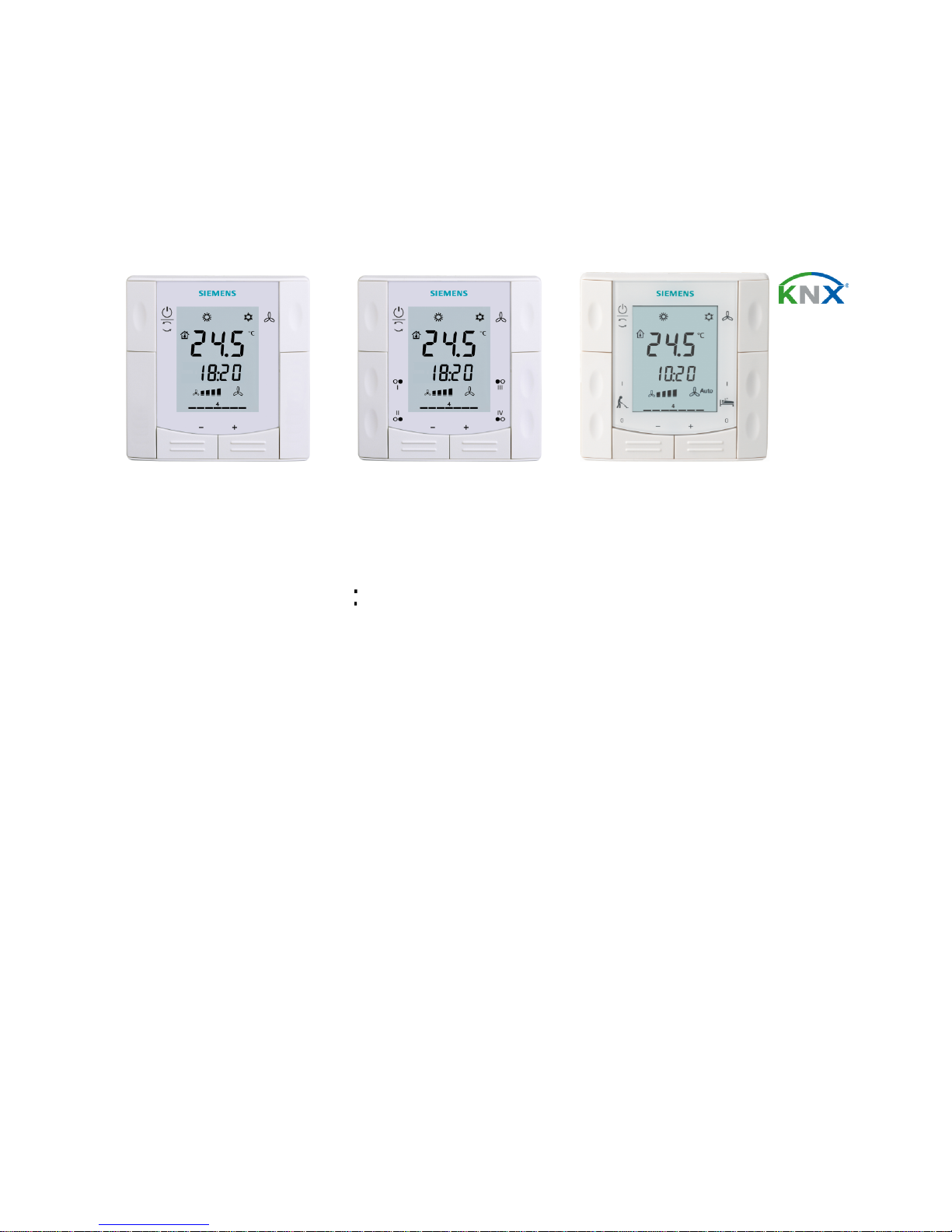
RDF301, RDF600KN
Semi-
flush mount
room t
hermostats
RDF301, RDF301.50..., RDF600KN
Basic d
ocumentation
Edition: 2.7
CE1P3171en
2017-12-07
RDF301.50, RDF600KN/S
communicating
,
RDF600KN/S
Building Technologies
RDF301.50H

2 / 94
Siemens RDF301, RDF301.50..., RDF600KN, RDF600KN/S Basic Documentation CE1P3171en
Building Technologies 2017-12-07
Contents
1. About this document .............................................................................. 4
1.1 Revision history ......................................................................................... 4
1.2 New functions ............................................................................................ 5
1.3 Reference documents ............................................................................... 5
1.4 Before you start ......................................................................................... 7
1.4.1 Copyright ................................................................................................... 7
1.4.2 Quality assurance ..................................................................................... 7
1.4.3 Document use / request to the reader ...................................................... 7
1.5 Target audience, prerequisites .................................................................. 8
1.6 Glossary .................................................................................................... 8
2. Summary .................................................................................................. 9
2.1 Types ......................................................................................................... 9
2.2 Ordering .................................................................................................... 9
2.3 Functions ................................................................................................... 9
2.4 Integration via KNX bus .......................................................................... 11
2.5 Equipment com binations ......................................................................... 13
2.6 Accessories ............................................................................................. 13
3. Functions ............................................................................................... 14
3.1 Temperature control ................................................................................ 14
3.2 Operating m odes ..................................................................................... 15
3.2.1 Different ways to influence the operating mode ...................................... 16
3.2.2 Communication ex amples ....................................................................... 20
3.3 Room temperature setpoints ................................................................... 25
3.3.1 Description .............................................................................................. 25
3.3.2 Setting and adjusting setpoints ............................................................... 27
3.4 Applications overview .............................................................................. 28
3.4.1 Applications for fan coil systems ............................................................. 29
3.4.2 Applications for Universal systems* ........................................................ 30
3.4.3 Applications for heat pump systems ....................................................... 31
3.5 Additional functions ................................................................................. 32
3.6 Control sequences .................................................................................. 35
3.6.1 Sequences overview (setting via parameter P01) .................................. 35
3.6.2 Application m ode ..................................................................................... 36
3.6.3 2-pipe fan coil unit ................................................................................... 38
3.6.4 2-pipe fan coil unit with electric heater .................................................... 39
3.6.5 4-pipe fan coil unit ................................................................................... 41
3.6.6 Chilled / heated ceiling and radiator applications* .................................. 42
3.6.7 Compressor applications ......................................................................... 43
3.6.8 Setpoints and sequences ........................................................................ 44
3.7 Control outputs ........................................................................................ 46
3.7.1 Overview ................................................................................................. 46
3.7.2 Control outputs configuration (setting via DIP switches or tool) ............. 47
3.8 Fan control .............................................................................................. 48
3.9 Multifunctional input, digital input ............................................................ 51
3.10 Handling faults ........................................................................................ 53
3. 11 KNX communications .............................................................................. 54

3 / 94
Siemens RDF301, RDF301.50..., RDF600KN, RDF600KN/S Basic Documentation CE1P3171en
Building Technologies 2017-12-07
3.11.1 S-Mode .................................................................................................... 54
3.11.2 LTE Mode ................................................................................................ 54
3.11.3 Zone addressing in LTE Mode (in conjunction with Synco) .................... 55
3.11.4 Example of heating and cooling demand zone ....................................... 57
3.11.5 Send heartbeat and receive timeout ....................................................... 58
3.11.6 Startup ..................................................................................................... 58
3.11.7 Heating and cooling demand .................................................................. 58
3.11.8 Fault function on KNX ............................................................................. 59
3.11.9 KNX switching groups (RDF600KN/S, RDF301.50, RDF301.50H only) 60
3.12 Communication objects (S-Mode) ........................................................... 62
3.12.1 Overview ................................................................................................. 62
3.12.2 Description of communication objects .................................................... 64
3.13 Communication objects (LTE-Mode) ....................................................... 67
3.14 Control parameters ................................................................................. 68
3.14.1 Parameter setting via local HMI .............................................................. 68
3.14.2 Parameter setting / download via tool ..................................................... 69
3.14.3 Parameters of the "Service level" ........................................................... 70
3.14.4 Parameters of the "Expert level with diagnostics and test" ................... 71
4. Handling ................................................................................................. 74
4.1 Mounting and installation ........................................................................ 74
4.2 Commissioning........................................................................................ 75
4.3 Operation ................................................................................................ 77
4.4 Remote operation.................................................................................... 78
4.5 Disposal .................................................................................................. 78
5. Supported KNX tools ............................................................................ 79
5.1 ETS ......................................................................................................... 79
5.1.1 Parameter settings in ETS ...................................................................... 79
5.2 ACS Service and Operating tool ............................................................. 80
5.2.1 Parameter settings in ACS ...................................................................... 81
5.2.2 Operation and monitoring with ACS ........................................................ 82
5.2.3 Operation and monitoring with OZW772 ................................................ 85
5.2.4 Operation and monitoring with RMZ972 ................................................. 85
6. Connection ............................................................................................ 86
6.1 Connection terminals .............................................................................. 86
6.2 Connection diagrams .............................................................................. 87
7. Mechanical design ................................................................................ 88
7.1 General ................................................................................................... 88
7.2 Dimensions ............................................................................................. 89
8. Technical data ....................................................................................... 90
Index 92

4 / 94
Siemens RDF301, RDF301.50..., RDF600KN, RDF600KN/S Basic Documentation CE1P3171en
Building Technologies 2017-12-07
1. About this document
1.1 Revision history
Edition Date Changes Section Pages
2.7 2017-11-30 - Add product name RDF600KN/S
- Update KNX and ACS logo
All All
2.6 2017-08-07 - Remove universal applications for RDF301 and
RDF301.50
- Add notes: RDF301.50 is not suitable for
applications in heating mode without fan
operations
All All
2.5 2017-02-17 Update “Send heartbeat and receive timeout” 3.11.5 57
2.4 2016-03-28 RDF600KN changes from SW V1.8 to V2.0
Presence detection function:
- V1.8 with only standard presence
- V2.0 with both standard presence (factory setting
P77 = 1) and hotel presence (P77 = 2)
Error handing and sensor errors
- V2.0 with additional alarms
Update Synco topology
All
3.10
2.4
All
54
11
2.3 2015-06-10 All Units:
Update mounting notes and connection diagrams
regarding overcurrent protection
Replace directives with declaration document number
4.1
6.2
8
74
87
90
2.2 June 2014 Added RDF301.50H
RDF600KN (SW V1.8)
- Update window contact and presence detector
function.
For all models:
Update with wiring and protection information
New S-Mode objects for Economy setpoint
All All
2.0 Oct 2012 Added RDF600…family All All
1.0 22 Jun 2010 First edition

5 / 94
Siemens RDF301, RDF301.50..., RDF600KN, RDF600KN/S Basic Documentation CE1P3171en
Building Technologies 2017-12-07
1.2 New functions
Availability of new functions depends on the software version used; see table
below.
RDF301 /
RDF301.50 /
RDF301.50H
RDF600KN
RDF600KN/S
Firmware updates SW = V4.1 SW < V1.8 SW = V1.8 SW >= V2.0
SW >= V1.0
Hotel presence
Standard presence mode
External sensor error
message Er3
Window contact
Operating mode switchover
contact
Fan stage in dead zone
(Comfort)
Fan start delay
Room temperature: S-Mode
object Economy heating
setpoint
Room temperature: S-Mode
object Economy cooling
setpoint
1.3 Reference documents
Subject Ref Doc No. Description
Semi-flush mount room
thermostats with KNX
communications,
RDF301, RDF301.50,
RDF600KN, RDF600KN/S
[1] CE1N3171 Data Sheet
[2] CE1B3171 Operating Instructions
[3]
[3a]
CE1M3171
CE1M3076.3
Mounting Instructions RDF301...
Mounting Instructions RDF600KN…
KNX Manual [4] Handbook for Home and Building Control – Basic Principles
(http://www.knx.org/knx-en/training/books-documentation/knx-association-
books/index.php)
Synco and KNX (see
www.siemens.com/synco
)
[5] CE1N3127 KNX bus, Data Sheet
[6] CE1P3127 Communication via the KNX bus for Synco 700, 900 and
RXB/RXL, Basic Documentation
[7]
XLS template
in HIT
Planning and commissioning protocol,
communication Synco 700
[8] CE1N3121 RMB795 central control unit, Data Sheet
[9] CE1Y3110 KNX S-Mode data points
[10] -- Product data for ETS
[11] CE1J3110 ETS product data compatibility list
[12] 0-92168en Synco Application Manual
Desigo
engineering documents
[13] CM1Y9775 Desigo RXB integration – S-Mode
[14] CM1Y9776 Desigo RXB / RXL integration – Individual Addressing
[15] CM1Y9777 Third-party integration
[16] CM1Y9778 Synco integration
[17] CM1Y9779 Working with ETS
Apogee [18] 565-132 Installation Instructions: KNX driver for PXC Modular

6 / 94
Siemens RDF301, RDF301.50..., RDF600KN, RDF600KN/S Basic Documentation CE1P3171en
Building Technologies 2017-12-07
engineering documents [19] 127-1676 Technical Spec Sheet: KNX driver for PXC Modular
[20] 140-0804 Technical reference for KNX driver
[21] 140-0804 Application 6205 point map for RDF

7 / 94
Siemens RDF301, RDF301.50..., RDF600KN, RDF600KN/S Basic Documentation CE1P3171en
Building Technologies 2017-12-07
1.4 Before you start
1.4.1 Copyright
This document may be duplicated and distributed only with the express permission
of Siemens, and may be passed only to authorized persons or companies with the
required technical knowledge.
1.4.2 Quality assurance
This document was prepared with great care.
∂ The contents of this document are checked at regular intervals
∂ Any corrections necessary are included in subsequent versions
∂ Documents are automatically amended as a consequence of modifications and
corrections to the products described
Please make sure that you are aware of the latest document revision date.
If you find lack of clarity while using this document, or if you have any criticisms or
suggestions, please contact the Product Manager in your nearest branch office.
The addresses of the Siemens Regional Companies are available at
www.buildingtechnologies.siemens.com.
1.4.3 Document use / request to the reader
Before using our products, it is important that you read the documents supplied
with or ordered at the same time as the products (equipment, applications, tools,
etc.) carefully and in full.
We assume that persons using our products and documents are authorized and
trained appropriately and have the technical knowledge required to use our
products as intended.
More information on the products and applications is available:
∂ On the intranet (Siemens employees only) at
https://workspace.sbt.siemens.com/content/00001123/default.aspx
∂ From the Siemens branch office near you
www.buildingtechnologies.siemens.com or from your system supplier
∂ From the support team at headquarters fieldsupport-zug.ch.sbt@siemens.com if
there is no local point of contact.
Siemens assumes no liability to the extent allowed under the law for any losses
resulting from a failure to comply with the aforementioned points or for the
improper compliance of the same.
8 / 94
Siemens
RDF301, RDF301.50..., RDF600KN
Building Technologies
1.5
Target audience, prerequisites
This document assumes that users of the RDF
the ETS
and/or Synco ACS
It also presupposes that these users are aware of the specific conditions associ
ated with KNX.
In most countries, specific KNX know
certified by the
For
reference documentation, see section
1.6
Glossary
The inputs, outputs and parameters of an application can be influenced in various
ways. These are identified by the following symbols in this
Parameters identified by this symbol are set using
Parameters identified by th
Setting RDF KNX parameters is only supported by the following tool
versions:
– ETS3
or
– ACS v
ersion 5.11
Inputs and outputs identified by this symbol
They are called communication objects (CO).
The communication objects of the
partly in
LTE Mode
A list of the parameters is shown in section
ETS
ACS
STOP
Note!
, RDF600KN/S Basic D
ocumentation
KNX
thermostat
tools and able to use them.
-how is conveyed
through training centers
KNX Association (see www.knx.org/).
1.2.
document
ETS.
is symbol are set using
the ACS tool.
higher
or higher
communicate with other KNX devices.
RDF KNX
thermostats work
, and partly
in both. These objects are described accordingly.
3.13.
CE1P3171en
2017-12-07
s are familiar with
-
:
partly in S-Mode,
9 / 94
Siemens RDF301, RDF301.50..., RDF600KN, RDF600KN/S Basic Documentation CE1P3171en
Building Technologies 2017-12-07
2. Summary
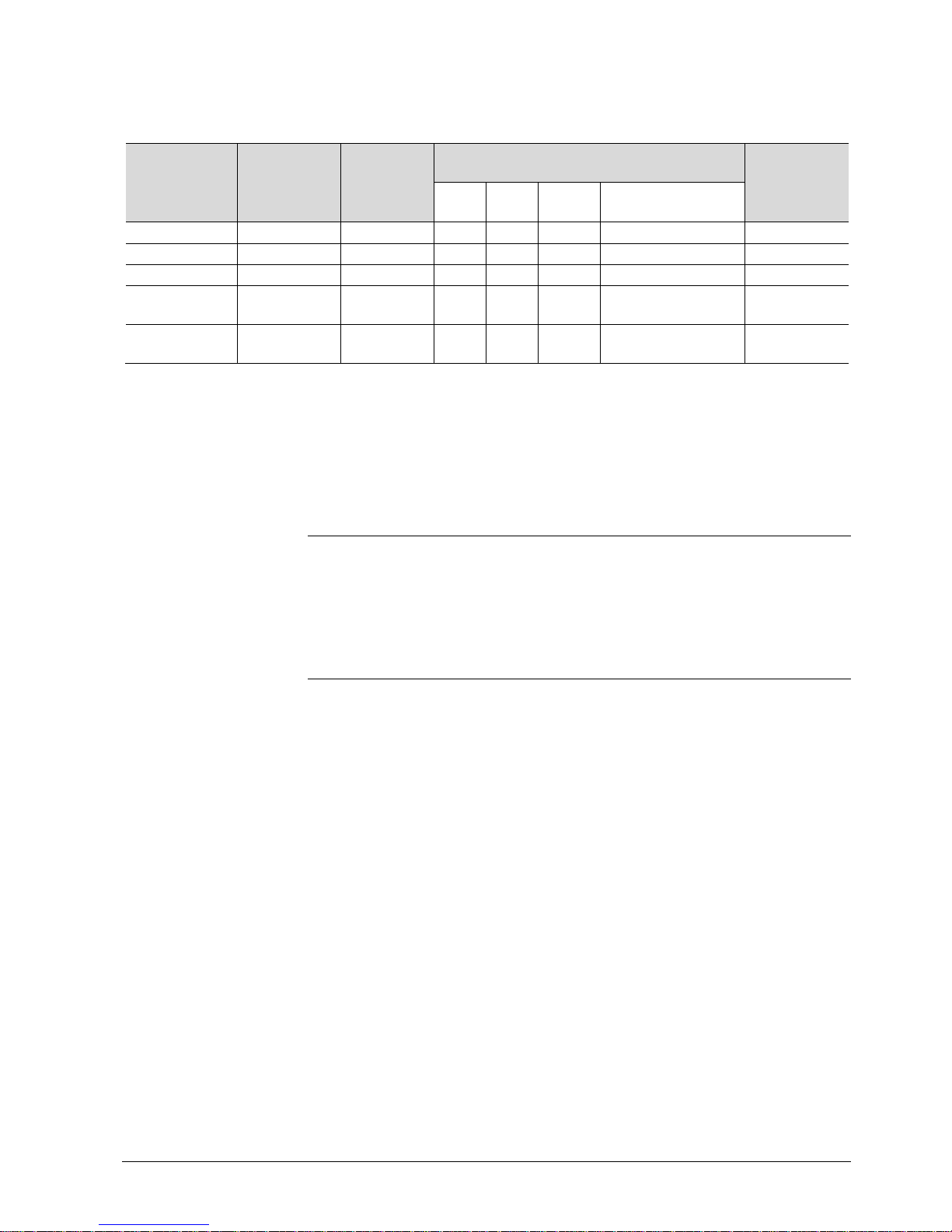
2.1 Types
Product no. Stock no.
Operating
voltage
Control outputs
Suitable
conduit
box
2)
3-
pos
ON/
OFFDC0..10 V
KNX switching
groups
RDF301 S55770-T104 AC 230 V
1
1)
2
1)
--
square
RDF301.50 S55770-T105 AC 230 V
1
1)
2
1)
--
square
RDF301.50H S55770-T334 AC 230 V
1
1)
2
1)
-- Hotel: MUR, DND
3)
square
RDF600KN S55770-T293 AC 230 V
1
1)
2
1)
--
Round or
square
RDF600KN/S S55770-T400 AC 230 V
1
1)
2
1)
--
Round or
square
1)
Selectable: ON/OFF or 3-position.
2)
Square conduit box.
Round CEE conduit box min 60 mm diameter and min 40 mm depth.
3)
MUR: Make Up Room, DND: Do Not Disturb.
2.2 Ordering
∂ When ordering, please indicate both product no. / stock no. and name:
E.g. RDF301 / S55770-T104 room thermostat.
∂ Order valve actuators separately.
2.3 Functions
Fan coil units via ON/OFF or modulating control outputs:
∂ 2-pipe system
∂ 2-pipe system with electric heater
∂ 4-pipe system
Chilled / heated ceilings (or radiators)* via ON/OFF or modulating control
outputs:
∂ Chilled / heated ceiling
∂ Chilled / heated ceiling with electric heater
∂ Chilled / heated ceiling and radiator / floor heating
* Not applicable for RDF301, RDF301.50
Compressors: Via ON/OFF control
∂ 1-stage compressors in DX type equipment
∂ 1-stage compressors in DX type equipment with electric heater
The room thermostats are delivered with a fixed set of applications.
The relevant application is selected and activated during commissioning using
one of the following tools:
∂ Synco ACS
∂ ETS
∂ Local DIP switch and HMI
Use

10 / 94
Siemens RDF301, RDF301.50..., RDF600KN, RDF600KN/S Basic Documentation CE1P3171en
Building Technologies 2017-12-07
∂ Operating modes: Comfort, Economy (Energy Saving) and Protection
∂ ON/OFF or 3-position control outputs (relay)
∂ Output for 3-speed or 1-speed fan
∂ Automatic or manual heating / cooling changeover
∂ Backlit display
∂ AC 230 V operating voltage
∂ RDF600KN… for round CEE conduit box, with min 60 mm diameter,
min 40 mm depth or recessed square CEE conduit box
with 60.3 mm fixed centers
∂ RDF301… for recessed square CEE conduit box
with 60.3 mm fixed centers
∂ Room temperature control via built-in temperature sensor or external room
temperature / return air temperature sensor.
∂ Changeover between heating and cooling mode (automatic via local sensor or
bus, or manually).
∂ Selection of applications via DIP switches or commissioning tool.
∂ Select operating mode via operating mode button on the thermostat.
∂ Temporary Comfort mode extension.
∂ 1- or 3-speed fan control (automatically or manually).
∂ Display of current room temperature or setpoint in °C and/or °F.
∂ Minimum and maximum limitation of room temperature setpoint.
∂ Button lock (automatically or manually).
∂ 2 multifunctional inputs, freely selectable for:
– Sensor for automatic heating / cooling changeover
– External room temperature or return air temperature sensor
– Dew point sensor
– Electric heater enable
– Fault input
– Monitor input for temperature sensor or switch state
RDF301…
– Operating mode switchover contact … (keycard, window contact, etc.)
RDF600KN…:
– Window contact
– Presence detector (Standard presence mode and Hotel presence )
See pages 15 & 18.
∂ Advanced fan control function, e.g. fan kick, fan start, selectable fan operation
(enable, disable or depending on heating or cooling mode).
∂ "Purge" function together with 2-port valve in a 2-pipe changeover system.
∂ Reminder to clean fan filters (adjust with P62).
∂ Floor heating temperature limitation.
∂ Reload factory settings for commissioning and control parameters.
Features
Type of mounting /
suitable conduit boxes
Functions

11 / 94
Siemens RDF301, RDF301.50..., RDF600KN, RDF600KN/S Basic Documentation CE1P3171en
Building Technologies 2017-12-07
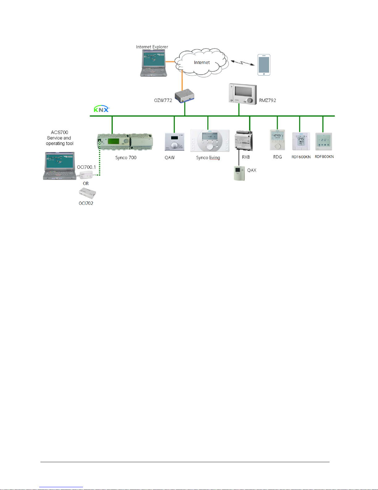
2.4 Integration via KNX bus
The RDF room thermostats can be integrated as follows:
∂ Integration into Synco 700 system via LTE Mode (easy engineering).
∂ Integration into Synco living via group addressing (ETS).
∂ Integration into Desigo and Apogee via group addressing (ETS) or
individual addressing.
∂ Integration into third-party systems via group addressing (ETS).
The following KNX functions are available:
∂ Central time program and setpoints, e.g. when using the RMB795 central
control unit.
∂ Outside temperature or time of day via bus displayed on thermostat.
∂ Remote operation and monitoring, e.g. using the RMZ792 bus operator unit.
∂ Remote operation and monitoring with web browser using the OZW772 web
server.
∂ Maximum energy efficiency due to exchange of relevant energy information,
e.g. with Synco 700 controllers (e.g. heating demand, cooling demand).
∂ RDF301.50 and RDF600KN/S only: 4 buttons to control KNX actuators via KNX
S-Mode
("switching groups" with functions such as switching, dimming, blinds control,
8-bit scene).
∂ RDF301.50H only: 4 buttons for Hotel applications to control via KNX S-Mode.
Same functions as RDF301.50, but with dedicated button labels for hotel
applications: Make Up Room, Do Not Disturb.
∂ Alarming, e.g. external fault contact, condensation, clean filter, etc.
∂ Monitoring input for temperature sensor or switch.
Engineering and commissioning can be done using…
– local DIP switches / HMI
– Synco ACS service tool
– ETS
The RDF room thermostats are especially tailored for integration into the Synco
700 system and operate together in LTE Mode. This extends the field of use of
Synco for individual room control in conjunction with fan coil units, VAV, chilled
ceilings and radiators.
Thanks to S-Mode extension to the QAX9x3 central apartment unit, communicating
room thermostats can be easily integrated into Synco living systems. Using the SMode data points of the central apartment unit, additional room information can be
exchanged with the room thermostat via KNX TP1 (RF function is not available on
the room thermostats). To make the integration, the ETS engineering tool is
required.
Synco 700
Synco living
12 / 94
Siemens RDF301, RDF301.50..., RDF600KN, RDF600KN/S Basic Documentation CE1P3171en
Building Technologies 2017-12-07
Synco 700 Building automation and control system (BACS)
Synco living Room automation and control system
RDG..., RDF… Room thermostats
OZW772 Web server
RMZ792 Bus operator unit
QAW... Room unit
ACS Service tool using OCI700.1 and OCI702 (OCI700.1
and OCI702 are delivered with a service cable which
can be plugged into the service connector on a Synco
controller)
RXB Room controllers
QAX Room unit for RXB room controllers
The RDF KNX devices can be integrated into the Siemens building automation and
control systems (BACS) Desigo / Apogee or into 3rd-party systems. For integration,
either S-Mode (group addressing) or individual addressing can be used.
Synco topology
Legend:
Desigo, Apogee and
third-party systems
RDF600KN/S
Siemens
RDF301, RDF301.50..., RDF600KN
Building Technologies
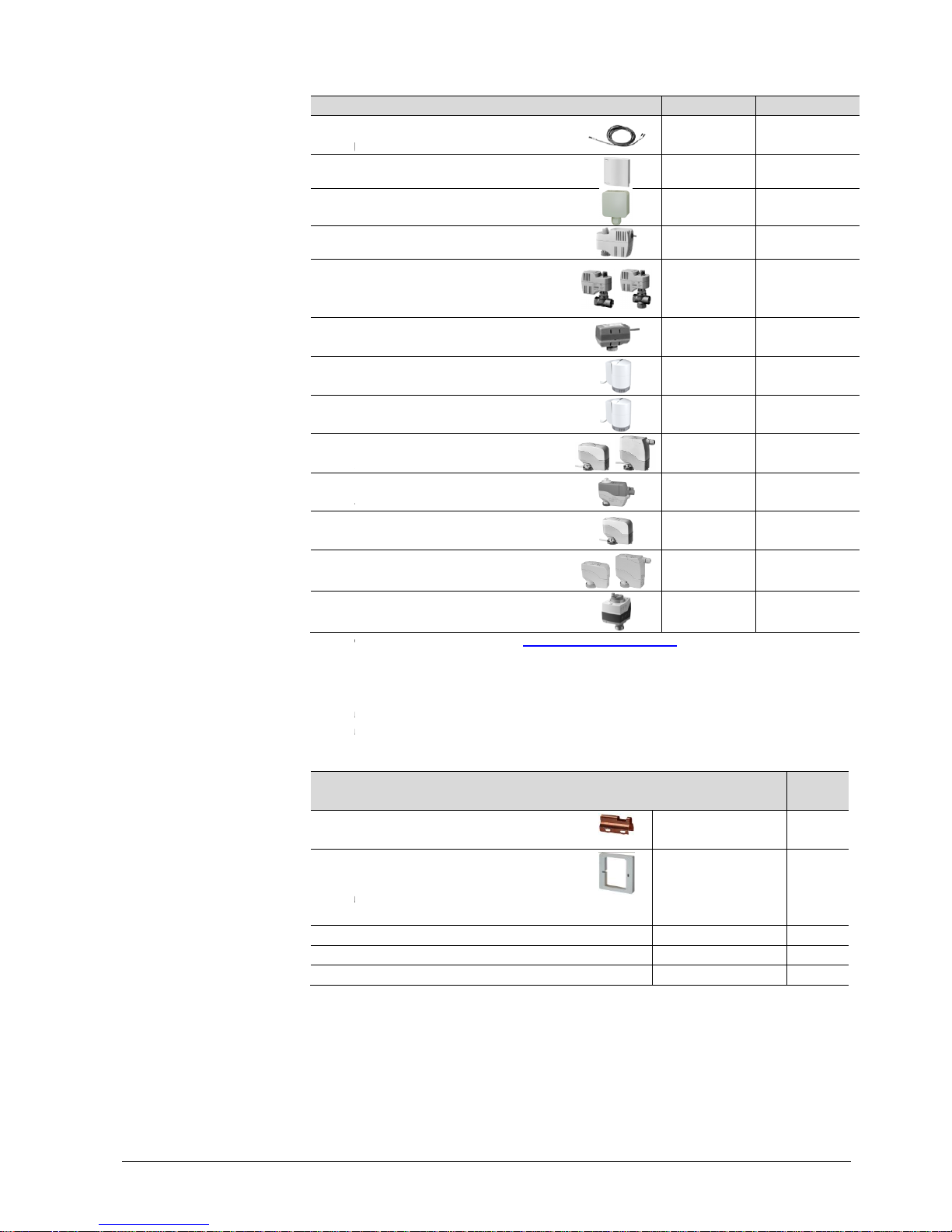
2.5
Description
Cable
changeover sensor
Room temperature sensor
Condensation
Electromotoric
Electromotoric
actuator
(only
available in AP, UAE, SA and IN)
Zone valve actuator
(only available in AP, UAE, SA and IN)
Thermal actuator (for radiator valves)
NO
Thermal actuator
(for small valves 2.5 mm)
Electrical actuator, 3
(for radiator valves)
Electrical actuator, 3
(for 2
-
Electrical actuator, 3
(for small valves 2.5 mm)
Electrical actuator, 3
(for small valves 5.5 mm)
Electrical actuator, 3
*) The documents can be downloaded from
Note:
For the
of the selected actuators and to this list, depending on which value is lower:
∂
Parallel operation of max 6 SS… actuators (3
∂
Parallel operation of max 10
2.6
Description
Changeover mounting kit
(50
pcs/package)
Pla
stic mounting bracket
moun
t thermostats RDF301... for
increasing the headroom in the conduit
box
by 10mm
KNX Power supply 160 mA (Siemens
KNX Power supply 320 mA (Siemens
KNX Power supply 640 mA (Siemens
ON/OFF actuators
3-position actuators
, RDF600KN/S Basic D
ocumentation
Equipment combinations
Product no.
temperature sensor or
QAH11.1
QAA32
monitor
QXA21..
ON/OFF actuator
SFA21...
ON/OFF valve and
MVI… /
MXI…
SUA…
STA23...
, NC
STP23...
-position
SSA31...
-position
and 3-port valves / V…P45)
SSC31
-position
SSP31
-position
SSB31...
-position
SAS31…
http://siemens.com/bt/download
maximal number of actuators in parallel, refer to information in the data sheets
-
pos) is possible
ON/OFF
actuators is possible
Accessories
Product no / SSN
ARG86.3
for semi-flush-
ARG70.3
BT LV)
5WG1 125
BT LV)
5WG1 125
BT LV)
5WG1 125
13 / 94
CE1P3171en
2017-12-07
Data sheet
*)
1840
1747
A6V10741072
4863
4867
4832
4884
4884
4893
4895
…
4864
4891
4581
.
.
.
Data
sheet
N3009
N3009
-1AB02
--
-1AB12
--
-1AB22
--
14 / 94
Siemens
RDF301, RDF301.50..., RDF600KN
Building Technologies
3.
Functions
3.1
Temperature control
S
etting of the control parameters (P01
is described in section
The
thermostat
temperature sensor (QAA32), or external return air temperature sensor (QAH11.1),
and main
tains the setpoint by
and/or cooling equipment. The following control outputs are available
∂ ON/
OFF∂Modulating PI/P control with 3
applications
The switching differential
cooling mode (adjustable via parameters P30 and P31).
The integral action time
minutes (
RDF600KN
The display shows the acquired room temperature or the
ble via parameter P06. The factory setting displays the
Use parameter P04 to
needed.
The acquired room temperature (internal or external
information on the
∂ With
automatic
indicate that the system currently heats or cools (heating or cooling output is
activated).
∂ With
manual
currently operates in heating or cooling mode. Thus, the symbols are displayed
even when the thermostat operates in the neutral zone.
Concurrent display of the current temperature or setpoint in
P07 = 1
) is possible on the
The outside temperature can be displayed on the room thermostat
parameter P07
In
LTE Mode
zone 31.
In S-
Mode
KNX sensor device.
Time of day via bus can be displayed on the room thermostat
P07 = 3
or
The information can be received from a Synco controller with
functionality or any other KNX device if the corresponding communication object is
bound.
∂
When an application program is downloaded to the Synco devices via
correct group addresses need to be downloaded as well to display the time of
day on the
General note:
Parameters
Temperature control
Display
Room temperature
/
Concurrent display of
°C and °F
Outside temperature via
bus
Time of day via bus
Note:
, RDF600KN/S Basic D
ocumentation
,
etc., mentioned throughout the document)
3.13.
acquires the room temperature via built-
in sensor, external room
delivering
actuator control commands to heating
control (2-position)
-position control output
(only for 2
)
or proportional band
is 2 K for heating mode and 1 K for
for modulating
PI control is 5 minutes
), adjustable via parameter P35.
Comfort
current room temperature.
change the room temperature
display
sensor
bus.
changeover or continuous heating / cooling, symbols
changeover (P01 = 2), symbols /
indicate that the system
thermostats.
=
2. This temperature value has only information character.
,
the outside temperature can only be received on
, the corresponding communication object need
s
4. The display format is either in 12- or in 24-
hour
room thermostat (see Synco Knowledge
Base
CE1P3171en
2017-12-07
:
-pipe
(RDF301...) and 45
setpoint, selecta-
from °C to °F as
) is also available as
/
°C and °F (parameter
by setting
outside temperature
to be bound with a
by setting parameter
format.
time master
ETS, the
- KB771).

Siemens
RDF301, RDF301.50..., RDF600KN
Building Technologies
3.2
The thermostat's operating mode can be influenced in different
Specific
The thermostat sends the
The following operating modes are available:
In Auto Timer mode the room operating mode is commanded via bus.
Auto Timer is replaced by Comfort when no time schedule via bus is present
In Comfort mode, the thermostat maintains the Comfort setpoint. This setpoint can
be defined via par
It can be locally adjusted via the
In Comfort mode, the fan can be set to automatic or manual fan speed: Low,
medium or high.
Standard presence
The thermostat switches to
KNX)
is active
Hotel presence
When
hotel
and
the
previous operating mode set by the hotel guests.
The setpoints (less heating and cooling than in Comfort mode) can be defined via
parameters P11 and P12.
The thermostat switches to
–
the operating mode button is pressed (only possible if parameter P02 is set to 2)
–
Economy is sent via bus
–
an operating mode switchover contact
presence detec
-
"Window state" is sent
presence detector (P02 is irrelevant) *)
In Protection mode, the system is...
–
protected against frost (factory setting 8 °C, can be disabled or changed via
P65)
–
protected against overheating (factory setting OFF, can be enabled or changed
via P66)
No other opera
via bus.
The thermostat switches to Protection mode when...
–
the operating mode button is pressed
–
Protection is sent vi
– the
window contact
–
"Window state" is sent
*)
Refer to chapter
contact (RDF301
(
RDF600KN
Room operating mode:
State
Auto Timer
Comfort
Presence detector
(RDF600KN…)
Economy
Room operating mode:
Window state
(RDF301…)
Protection
Room operating mode:
Window state
(RDF600KN…)
Note:
, RDF600KN/S Basic D
ocumentation
Operating modes
heating and cooling setpoints
are assigned to each
effective
room operating mode on the bus.
ameters P8, P9 and P10.
+/- buttons or via bus.
mode:
Comfort mode when
the presence detector
(room is occupied). *)
mode:
guests leave their rooms
, the thermostat switches to Economy mode
local HMI (keys) is locked. Upon
occupancy, the thermostat
Economy mode when...
on RDF301…
(e.g. keycard contact
tor, window contact) is active. *)
to the RDF301
via bus, e.g. from a KNX switch or a KNX
ting mode can be selected locally if Protection mode is commanded
and are displayed.
a bus
on RDF600KN is active
(open window)
to the RDF600KN
via bus, e.g. from a KNX switch *)
3.2.1
for detail regarding the operating mode switchover
...), window contact (RDF600KN…
) and presence detector
…).
15 / 94
CE1P3171en
2017-12-07
ways (see below).
operating mode.
(local or on
returns to the
.
16 / 94
Siemens
RDF301, RDF301.50..., RDF600KN
Building Technologies
3.2.1
The operating mode can be influenced by different interventions.
The source of the
"Cause"
diagnostic data
OZW772.
Source Description
Local operation
via operating
mode button
∂
Operating mode is not Auto
∂
No time schedule via bus
∂
Temporary Comfort extension is active
∂
Operating mode switchover contact
∂ Window
contact
∂
Presence detector
Bus command
Room op. mode
∂
"Window state" sent via bus
∂
"Window state" sent via bus
∂ "
Presence detector
1)
∂
Time schedule available via bus
⇓
local operating mode is set to Auto
∂
Time schedule sends Protection mode via bus
⇓
operating mode cannot be changed locally
1)
RDF600KN SW version <
switchover contact
The following table shows the priorities of different interventions.
A lower number means a higher priority.
Priority Description
•
Commissioning
‚
Protection mode via bus
from time schedule
ƒ
Operating mode
switchover contact
(RDF301…)
ƒ
Window contact
(RDF600KN…)
1)
ƒ
"Window state" via bus
„
Presence detector
(RDF600KN…)
1)
Source for change of
operating mode
ACS
Priority of operating
mode interventions
, RDF600KN/S Basic D
ocumentation
Different way
s to influence the operating mode
effective room operating mode state
can be monitored using the
point in the ACS tool
, operator unit RMZ792 or
Value of DP "Cause"
Timer
Room operating mode
(pre-
selection
Timer
function
(RDF301..)
Room operating mode contact
(RDF600KN…)
1)
Window switch
(RDF600KN…)
1)
Presence detector
(RDF301….)
Room operating mode contact
(RDF600KN…)
1)
Window switch
" sent via bus (RDF600KN…)
Presence detector
Timer
Time switch
V1.8 works like RDF301…
with the operating mode
.
Remark
In parameter
setting mode (highest priority)
command an operating mode independent of all other settings
or intervention via bus and local input.
Protection mode, sent by a
time schedule
It cannot be overridden by the user n
or by an operating mode
switchover contact.
If the contact is closed, the operating mode changes to
Economy
. This overrides the operating mode on the
If the contact is closed, the operating mode changes to
Protection
. This overrides the operating mode on the
thermostat.
"Window state" sent via bus has the same effect as the
operating mode switchover contact
(on RDF301…)
window contact (on RDF600KN).
Note: Only one input source must be used, either local input
X1/X2 or KNX bus.
Standard presence mode: The thermostat switches to Comfort
mode when the presence detector (local or on KNX)
(room is occupied).
*)
Hotel presence mode: When hotel guests leave the
thermostat switches to Economy mode and
is locked. Upon
occupancy, the thermostat
previous operating mode set by the hotel guests.
CE1P3171en
2017-12-07
web server
selector
)
, you can always
, has priority 2.
thermostat.
local
or local
is active
ir rooms, the
the local HMI (keys)
returns to the

Siemens
RDF301, RDF301.50..., RDF600KN
Building Technologies
„
Presence
detector via
bus (on
RDF600KN
1)
„
Operating mode button
„
Operating mode via bus
„
Temporary extended
Comfort mode via
operating mode button
„
Time schedule via bus
1)
If a time schedule
Timer
mode
Comfort
The display shows the Auto Timer mode symbol
effective room
By pressing the operating mode button, you can change to another operating
mode.
Automatic
Each time the time schedule sends a new operating mode (switching event), the
operating mode of the thermostat is set back to Auto
that the room temperature is maintained according to the time schedule.
If the time
either into
No intervention is possible neither by the user nor by an operating mode switch
over contact,
display w
The operating mode can be selected
The behavior of the operating mode
parameter P
P02 Without time
schedule
With time
dule via
1 ⇓
⇓
2 ⇓⇓
⇓
Auto Timer mode
with time schedule via
bus
Behavior when bus
sends new operating
mode
Pre-Comfort via bus
Behavior when bus
sends Protection
Availability of Economy
mode
, RDF600KN/S Basic D
ocumentation
…)
"Presence detector" sent via bus has the same effect as the
local presence detector.
The user can switch the operating mode using the operating
mode button.
The operating mode can be changed via bus
The operating mode can be
temporarily set from Economy to
Comfort by pressing the operating mode button, if...
– Economy was sent via bus
–
extended Comfort period >0 (parameter P68)
The last intervention wins, either locally or via bus
The operating mode sent via bus can be overridden by all other
interventions.
Exception: Protection mode has priority 2
Note: If the time schedule switches from Comfort to Economy,
but the presence detector is still active (room occupied), the
thermostat
continues to work in Comfort mode for the period of
occupancy.
RDF600KN SW version < V1.8
works like RDF301… with the operating
mode switchover contact as window contact or
presence detector
via bus is present, e.g. from central
control unit
is active. The thermostat
automatically changes
and Auto Economy according to the
time schedule via bus.
along with the symbol for the
operating mode (Auto Comfort or
Auto
fan is the default f
an speed in Auto Timer mode.
T
imer mode. This
schedule sends Pre-Comfort mode
, then this mode will be transformed
Economy (factory setting) or Comfort (
selectable
i
f Protection mode is set by the time sched
hen the user presses a button.
locally via the operating mode button.
button
(user profile)
02, factory setting is P02 = 1.
sche-
bus
Description
∂ Switching manually between 2
available (factory setting).
∂ Suited for hotel guest rooms
or commercial buildings.
∂ If a time schedule via bus
is available, then the Comfort
mode can be temporarily extended (see
⇓⇓
∂ Switching manually between 3
∂
Suited for homes and rooms where manual switching to
17 / 94
CE1P3171en
2017-12-07
.
.
.
.
, then the Auto
between Auto
Economy ).
is to assure
via parameter P88).
-
ule. OFF flashes on the
can be defined via
modes, Economy is not
below).
modes.

18 / 94
Siemens
RDF301, RDF301.50..., RDF600KN
Building Technologies
The thermostat can be forced into Economy mode (e.g. when a window is opened,
when a presence detector signals "no one present", when the keycard of a hotel
room is withdrawn,
X2. Set parameter P38, P40 to 3.
ineffective and "
active.
The thermostat can be forced into
The contact can be connected to multifunctional input X1, X2. Set parameter P38,
P40 to 3.
User
contact is active.
RDF600KN SW version <
switchover function
The function
the KNX signal "Window state", e.g.
detector.
Only one input source must be used, either local input X1/X2
User operations are ineffective and
switch
over
The operating mode can be changed to Comfort and back to
depending of the room occupancy (room occupied or not occupied
detector or keycard)
Behavior w
∂
Whenever the presence detector is activated then the operating mode of the
thermostat goes to Comfort
∂
Whenever the presence detector is deactivated then the operating mode
to Economy
Behavior w
∂
When Time
-
Presence detector has
∂
When Time
-
Whenever the presence detector is activated then the operating mode goes
to Comf
-
Whenever the presence detector is deactivated then the operating mode
goes to (Auto) Economy
∂
When Time
-
Whenever the presence detector is activate
in Comfort
-
Whenever the presence detector is
keeps in Comfort
Important:
the operating mode keeps in Comfort mode until the Presence detector is
inactive
The contact (e.g. a card reader) can be connected to multifunctional input X1,
X2 (set parameter P38 or P40 to 10) or the occupancy is sent via bus from a KNX
Operating mode
switchover contact
(window contact)
(RDF301…)
Window contact
(RDF600KN…)
Note:
Room operating mode:
Window state
Note:
Room operating mode:
Presence detector
(RDF600KN…)
Standard presence mode:
(factory setting P77=1)
Note:
, RDF600KN/S Basic D
ocumentation
Economy mode is desired.
etc). The contact can be connected to multifunctional input X1,
P02 is not relevant.
User
OFF" is display
ed if the operating mode switch
Protection mode
when the window is opened
operations are ineffective and "OFF"
is displayed if the window
V1.8 works like RDF301…
with the operating mode
.
(operating mode switchover or window contact)
from a KNX switch or a KNX presence
"OFF" is displayed i
f the operating mode
/ window contact is active, or if "Window
state" is sent via bus.
.
ithout time schedule:
.
.
ith time schedule via bus:
-switch is on Protection
not influence on operating mode.
-switch is on Economy
ort.
.
-switch is on Comfort
d t
hen the operating mode keeps
.
deactivated then the operating mode
.
When Time-
switch goes to Eco but Presence detector is still active
.
CE1P3171en
2017-12-07
operations are
over contact is
.
is also available via
or KNX bus.
Economy mode
, via presence
goes
,

19 / 94
Siemens RDF301, RDF301.50..., RDF600KN, RDF600KN/S Basic Documentation CE1P3171en
Building Technologies 2017-12-07
presence detector sensor: Only one input source must be used, either local input
X1/X2 or KNX bus.
This function can be selected via parameter P77=2.
The presence detector status can be set via card reader or presence detector
connected to the local multifunctional input (set P38 or P40 to 10) or via KNX (SMode).
Response when the room is unoccupied, i.e. when the key card is removed from
the card reader or when the presence detector no longer detects movement.
∂ The operating mode of the thermostat switches to Economy.
∂ Changing the operating mode via local HMI is not possible (locked HMI) to
ensure Economy is active when rooms are unoccupied.
The operating mode can still be changed via bus, e.g. the hotel front desk switches
the operating mode to Protection upon check-out or extended vacancy.
Response when the room is occupied, i.e. when the key card is inserted or when
the presence detector detects movement.
∂ The thermostat returns to the last operating mode set for occupancy (either
Protection or Comfort)
If the operating mode is changed via bus during vacancy, the change is not based
on detection, e.g. front desk can set the operating mode to Comfort after guests
check in.
Hotel presence mode:
(P77=2)
Note:
Note:

20 / 94
Siemens RDF301, RDF301.50..., RDF600KN, RDF600KN/S Basic Documentation CE1P3171en
Building Technologies 2017-12-07
Comfort mode can be temporarily extended (e.g. working after business hour or on
weekends) when the thermostat is in Economy mode. The operating mode button
switches the operating mode back to Comfort for the period preset in P68.
Press the operating mode button again to stop the timer.
The following conditions must be fulfilled:
∂ mode selection via operating mode button is set to "Protection-Auto"
(P02 = 1) and the time schedule via bus is Economy.
∂ Parameter P68 (extend Comfort period) is greater than 0.
During the temporary Comfort mode extension, symbol appears.
If parameter P68 (extend Comfort period) = 0, extended Comfort cannot be
activated; pressing the operating mode button will switch the thermostat to
Protection.
If the operating mode switchover contact is active, pressing the operating mode
button will show "OFF" (blinking).
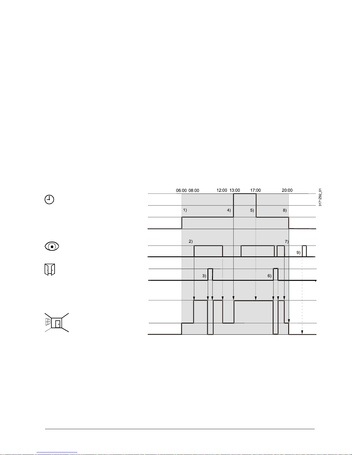
3.2.2 Communication examples
The following examples show two typical applications of a central time schedule in
conjunction with local control of the room operating mode.
The room operating mode in rooms 1…2 of a building is determined by the time
schedule. Window contacts are fitted in all rooms.
The following conditions are specified:
The rooms are used and controlled by the time schedule as follows:
– Night setback from 17:00 to 08:00 (Economy)
– Protection from 20:00 to 06:00
– Lunch break from 12:00 to 13:00 (Pre-Comfort).
The substitution (parameter P88) for Pre-Comfort via bus is set on the thermostats
as follows:
– Room 1: Comfort (1)
– Room 2: Economy (0).
Temporary timer to
extend the Comfort
mode

21 / 94
Siemens RDF301, RDF301.50..., RDF600KN, RDF600KN/S Basic Documentation CE1P3171en
Building Technologies 2017-12-07
Operating mode switchover
In room 1, the window is opened briefly, once in the morning, once in late
afternoon and once at night (1). Only the opening in the morning has a direct
impact on the effective room operating mode.
During lunch break, the time schedule changes to Pre-Comfort. The mode remains
in Comfort as set by parameter "Transformation Pre-Comfort" (P88 = 1).
Time schedule
Window contact
Room 1
Effective room
operating mode
Room 1
Comfort
Pre-Comfort
Economy
Protection
Window open
Window closed
Comfort
Economy
Protection
08:00
17:0013:0012:00
1)
06:00
20:00
1)
1)
2)
3171Z91
Example 1 (RDF301…)
22 / 94
Siemens RDF301, RDF301.50..., RDF600KN, RDF600KN/S Basic Documentation CE1P3171en
Building Technologies 2017-12-07
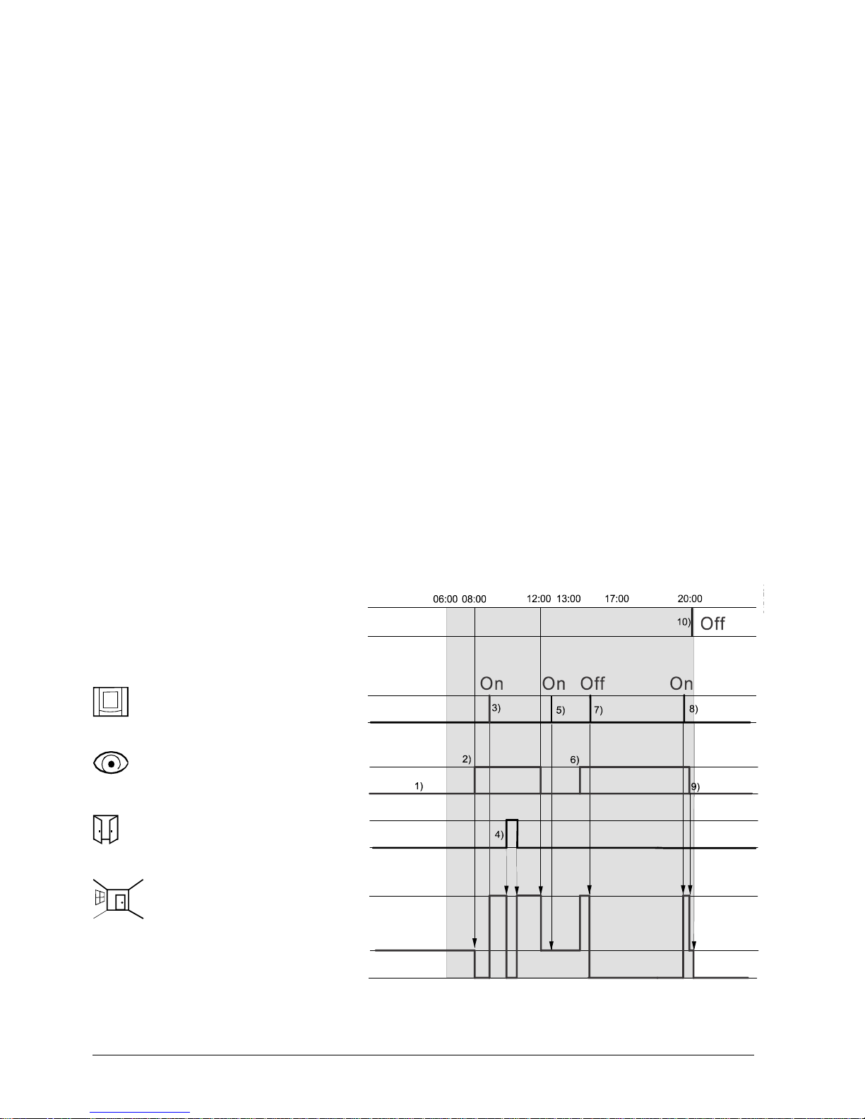
Interaction of user operation (operating mode button) and central time
schedule
In room 2, the window is opened briefly, once in the morning and once at night (1).
Only the opening in the morning has a direct impact on the effective room operating mode.
With the operating mode button, the operating mode can be changed between
OFF and Auto or temporary Comfort extension respectively.
∂ During lunch break, the time schedule changes to Pre-Comfort. The mode of
the thermostat changes to Economy as set by parameter "Transformation PreComfort". (P88 = 0) (6)
∂ During lunch break, the user changes the operating mode to Comfort
(temporary Comfort extension) by pressing the operating mode button. (2)
At 13:00, the timer is reset due to mode change of the central time schedule
∂ In the afternoon, the user switches the thermostat off by pressing the operating
mode button. (3) At 17:00 the user setting is reset to Economy by the time
schedule.
∂ At 19:30, the user again extends the Comfort mode (4). At 20:00, the timer is
reset by the time schedule.
∂ After 20:00, pressing the operating mode button has no effect, as the central
time switch sets the thermostat to Protection. (5)
Time schedule
Room operating
mode
Operating mode
button on the
thermostat
Window contact
Room 2
Effective room
operating mode
Room 2
Comfort
Pre-Comfort
Economy
Protection
Pressed
Window open
Window closed
Comfort
Economy
Protection
08:00
17:0013:0012:00
06:00
20:00
1)
1)
5)
2)
3)
4)
6)
3171Z92
Example 2 (RDF301…)
23 / 94
Siemens RDF301, RDF301.50..., RDF600KN, RDF600KN/S Basic Documentation CE1P3171en
Building Technologies 2017-12-07
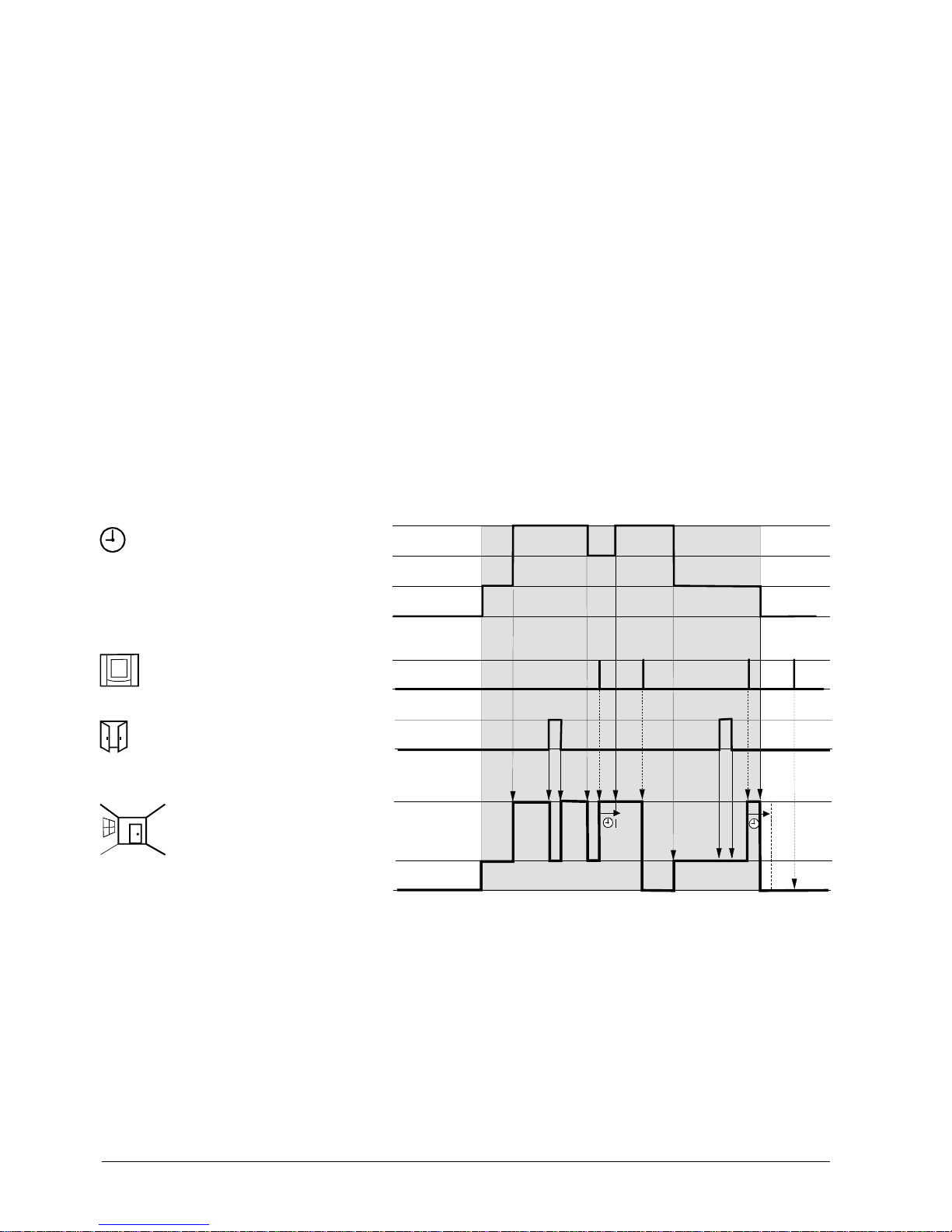
Application with "Window Contact", "Standard Presence Detector" and
central time schedule
In room 3 operating mode Comfort is possible between 6:00 and 20:00, based on
time schedule or occupancy period. Outside this time the operating mode remains
in Protection.
∂ At 6:00 the central set the operating mode to Economy. (1)
∂ In the morning, as soon as the presence is detected (8:00 – 12:00), the
operating mode will be switched to Comfort. (2)
∂ The user will briefly open the window and the operating mode switches to
Protection. (3)
∂ In the afternoon the time schedule set the Comfort mode from 13:00 to 17:00.
(4)
∂ After 17:00 the room is still occupied and the operating mode remains in
Comfort (occupancy via presence detector). (5)
∂ Later people open the window and left the room for a short time. Operating
mode switches to Protection as long as the window is open. (6)
∂ As soon as the room is unoccupied the thermostat switches to Economy. (7)
∂ At 20:00 the room is set to protection according to time schedule. (8)
∂ After this time, the occupancy detected via presence detection has not effect,
as the central time switch sets the thermostat to Protection. (9)
Time schedule
Room operating
mode
Presence
detector
Window contact
Room 3
Effective room
operating mode
Room 3
Comfort
Pre-Comfort
Economy
Protection
Occupied
Unoccupied
Window open
Window closed
Comfort
Economy
Protection
RDF600KN SW version < V1.8 works like RDF301… with the operating mode
switchover function.
Example 3 (RDF600…)
Note:
24 / 94
Siemens RDF301, RDF301.50..., RDF600KN, RDF600KN/S Basic Documentation CE1P3171en
Building Technologies 2017-12-07
Application with hotel presence detection function via key card reader
In room 4, hotel presence detection is selected via parameter P77, and the
multifunctional input X1/X2(set parameter P38 or P40 to 10) is connected to a card
reader in a hotel application.
∂ At 6:00 when the room is vacant, i.e. no key card inserted in the card reader,
the thermostat’s operating mode is set to Economy. (1)
∂ At 8:00 when the room is occupied, i.e. a key card inserted in the card reader,
the operating mode returns from Economy to the previous mode1)(2)
∂ A guest changes the operating mode to Comfort by pressing the operating
mode button. (3)
∂ The guest then opens a window and the operating mode immediately switches
to Protection. As soon as the window is closed, the operating mode is returns
to Comfort. (4)
∂ If the guest leaves the hotel room or removes the key card, the operating
mode returns to Economy, and the thermostat remains on Economy as the
local HMI2) is locked, i.e. the operating mode cannot be changed if no key card
is inserted. (5)
∂ When the guest returns to the hotel (room occupied), the operating mode
returns to the mode (Comfort) set previously by the guest. (6)
∂ When the guest turns off the room thermostat before going to sleep, the room
operating mode switches to Protection. (7)
∂ As the guest wakes up, he/she turns on the thermostat and the operating
mode switches to Comfort. (8)
∂ As soon as the room is unoccupied (guest leaves the room), the thermostat
returns to Economy to save energy. (9)
∂ When the guest checks out of the hotel, the operating mode can be set to
Protection via bus. (10)
Note:
1) The previous mode is the operating mode selected by either hotel guests via local
HMI, or the operating mode sent via bus.
2) Local HMI means operation by means of buttons, including setpoint adjustments,
fan speed, operating mode, etc.
Setting operating
mode via bus
Operating mode
button on the
thermostat
Key card reader
Window contact
Room 4
Effective room
operating mode
Room 4
Check out
Pressed
Occupied
Unoccupied
Window open
Window
closed
Comfort
Economy
Protection
RDF600KN SW version < V1.8 works like RDF301… with the operating mode
switchover function.
Note:
Example 4
(RDF600KN)

25 / 94
Siemens RDF301, RDF301.50..., RDF600KN, RDF600KN/S Basic Documentation CE1P3171en
Building Technologies 2017-12-07
3.3 Room temperature setpoints
3.3.1 Description
The factory setting for the Comfort basic setpoint is 21 °C and can be changed in
the thermostat’s EEPROM via parameter P08 or via bus with communication object
"Comfort basic setpoint". The last intervention always wins.
The Comfort setpoint can be adjusted via the +/- buttons,
or via bus from a remote device like a touchpanel, operating unit, etc.
The last intervention always wins.
If the "Temporary setpoint" function is enabled via parameter P69, the Comfort
setpoint adjusted via the +/- buttons or via bus is set back to the Comfort basic
setpoint stored in P08 when the operating mode changes.
For comfort or energy saving purposes, the setpoint setting range can be limited to
minimum (P09) and maximum (P10).
∂ If the minimum limit P09 is set lower than the maximum limit P10, both heating
and cooling are adjustable between these 2 limits.
∂ The customer adjusts the desired setpoint and the thermostat controls the room
temperature accordingly.
∂ For 4-pipe applications *), the selected comfort setpoint is in the middle of the dead
zone (P33). The unit stops to energize the heating / cooling outputs as soon as the
room temperature reaches the dead zone.
Example
5°C
40°C
25°C18°C
P10
P09
Cooling setpoint adjustable 18…25 °C
Heating setpoint adjustable 18…25 °C
∂ If the minimum limit P09 is set higher than the limit P10, then
– The setting range of cooling setpoint is from P09…40 °C in place of 5…40 °C
– The setting range of heating setpoint is from 5…P10 °C in place of 5…40 °C.
This allows the user to limit the maximum heating setpoint and the minimum
cooling setpoint. This concept helps to save energy costs.
∂ For 4-pipe applications *):
– The thermostat runs with the setpoint of the active sequence:
In heating mode, the heating setpoint is active and adjustable via rotary knob.
In cooling mode, the cooling setpoint is active and adjustable via rotary knob.
– Switching from the heating setpoint to the cooling setpoint and vice-versa
occurs when the room temperature reaches the adjusted limitation (P09 or
P10) of the inactive sequence. E.g. the thermostat is in heating sequence
and runs with the heating setpoint. When the room temperature reaches P09,
the thermostat switches to cooling mode and runs with the cooling setpoint, as
long as the room temperature does not drop below P10.
Example
5°C
40°C
25°C21°C
P09
P10
Cooling setpoint adjustable 25…40 °C
Heating setpoint adjustable 5…21 °C
For heating and cooling applications (e.g. 4-pipe):
– P09 is the setpoint for cooling and P10 the setpoint for heating.
– The setpoint cannot be adjusted via the rotary knob.
Use control parameters P11 and P12 to adjust the Economy mode setpoints.
The heating setpoint is factory-set to 15 °C, and the cooling setpoint to 30 °C.
Comfort mode
Temporary setpoint
Setpoint limitation
P09 < P10
(comfort concept)
P09 ≥ P10
(energy saving concept)
*) Note: RDF301...
for 4-pipe with P09 ≥ P10
Economy mode

26 / 94
Siemens RDF301, RDF301.50..., RDF600KN, RDF600KN/S Basic Documentation CE1P3171en
Building Technologies 2017-12-07
Use control parameters P65 and P66 to adjust the Protection mode setpoints.
The heating setpoint is factory-set to 8 °C (frost protection) and to OFF for cooling.
If a setpoint (Economy or Protection) is set to OFF, the thermostat does not control
the room temperature in the corresponding mode (heating or cooling).
This means no protective heating or cooling function and thus risk of frost in
heating mode or risk of overtemperature in cooling mode!
The Economy setpoints are accessible at the service level (P11, P12); the
Protection setpoints at the expert level (P65, P66).
Protection mode
Caution
Siemens
RDF301, RDF301.50..., RDF600KN
Building Technologies
3.3.2
Room temperature setpoints can be
–
set during commissioning
–
adjusted during runtime
The source ca
–
the local HMI
–
a tool
–
a central control unit
The thermostat stores the setpoints
–
in EEPROM in the form of parameters
–
in the runtime memory
The table below shows the interrelations:
Setpoint setting
Commis
sioning
– HMI
– Tool download
Input
Comfort basic setpoint
Dead zone Comfort
1)
Setpoints Heating
Setpoints Cooling
Setpoint Economy Heating
Setpoint Economy Cooling
Setpoints Heating
Setpoints Cooling
Setpoint Protection Heating
Setpoint Protection Cooling
Current
runtime
setpoints in
thermostat
Input
Mode
Comfort setpoint
Setpoint shift H
Setpo
Economy Heating
Economy Cooling
Setpoint shift H
Setpo
Protection Heating
Protection Cooling
Effective room operating mode
1)
Only required for heating AND cooling applications
2)
LTE Mode
3) S-
Mode:
The
current
on the bus for
Comfort basic setpoint
Comfort setpoint
Economy heating
setpoint
Economy cooling
setpoint
Current setpoint
, RDF600KN/S Basic D
ocumentation
Setting and adjusting setpoints
n be
Stored in EEPROM
of thermostat
LTE Mode
Input
S-Mode
Comfort basic setpoint
P08 Comfort basic setpoint
P33 Dead zone Comfort
P11
P12
P65 Protection Heating
P66 Protection Cooling
Setpoint
adjustment
LTE2)Input
S-Mode
3)
Local ope
-
ration
int shift C
Comfort setpoint + / - buttons
int shift C
Current setpoint (used by the
thermostat for temperature control)
(see
: the shift is added to the local shift.
the last intervention wins, either S-
Mode input or local operation
setpoint
(used by the thermostat for temperature control
use in the central control unit.
27 / 94
CE1P3171en
2017-12-07
1)
Economy Heating
Economy Cooling
New
current
runtime setpoints
in thermostat
Comfort setpoint
Economy Heating
Economy Cooling
Protection Heating
Protection Cooling
section 3.6.8).
.
) is available
28 / 94
Siemens RDF301, RDF301.50..., RDF600KN, RDF600KN/S Basic Documentation CE1P3171en
Building Technologies 2017-12-07
∂ The supported communication objects are different in LTE Mode and S-Mode.
∂ Changes via the local HMI or via tool have the same priority (last always wins).
∂ Setting the Comfort basic setpoint will reset the runtime Comfort setpoint to the
basic setpoint.
∂ Central setpoint shift is used for summer / winter compensation in particular.
∂ Setpoint shift does not affect the setpoints stored in parameters P08, P11, P12,
P33.
∂ Local shift and central shift are added together.
∂ Applies only to Comfort and Economy setpoints; Protection setpoints are not
shifted centrally.
∂ The resulting (current) setpoint heating and cooling is limited by the Protection
setpoint; if Protection setpoint is OFF, then minimum 5 °C and maximum 40 °C
are used.
∂ The resulting setpoints for cooling and heating of the same operating mode have
a minimum distance of 0.5 K between them.
∂ The result of local and central shift, together with the room operating mode, is
used by the thermostat for temperature control (current setpoint).
∂ The room thermostat always adopts the received setpoints from the controller
RMB795. Thus the Comfort setpoints locally adjusted on the RDF600KN room
thermostats are overwritten by the Comfort setpoints of the room group
(i.e. within every 15 min).
∂ On RMB SW Version >= 2.0 it is possible to define under which circumstances
the controller has to send out the setpoints:
- Always (every 15min)
- Not in Comfort mode
- Only when changed
∂ See "Setpoint priority" and "Setpoint Master" functions on RMB795B.
∂ RDF600KN SW version < V1.8: The local Comfort setpoints are overwritten only
if the RMB setpoints are changed.
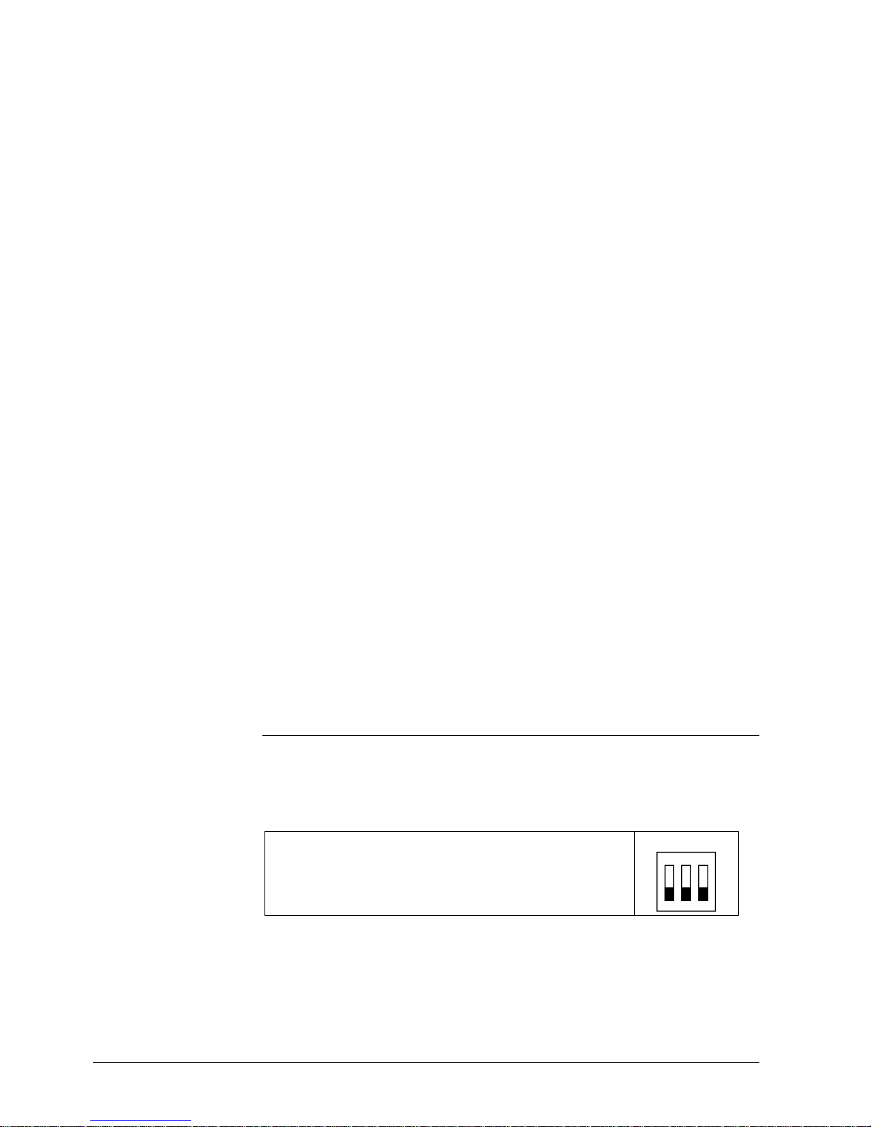
3.4 Applications overview
The thermostats support the following applications, which can be configured using
the DIP switches inside the front panel of the unit or a commissioning tool.
All DIP switches need to be set to OFF (remote configuration, factory setting) to
select an application via commissioning tool.
Remote configuration, via commissioning tool (factory set)
∂ Synco ACS
∂ ETS
DIP switches
1ON2 3
The tools provide the applications described in section 3.4.1.
For universal applications (chilled ceiling, etc.) and compressor applications, refer
to section 3.6.6 and section 3.6.7.
General notes:
Notes on setpoint
adjustment (LTE Mode
with Synco only)
Setpoint priority,
Setpoint Master RMB
(RDF600KN)
Note:
Remote configuration
29 / 94
Siemens RDF301, RDF301.50..., RDF600KN, RDF600KN/S Basic Documentation CE1P3171en
Building Technologies 2017-12-07
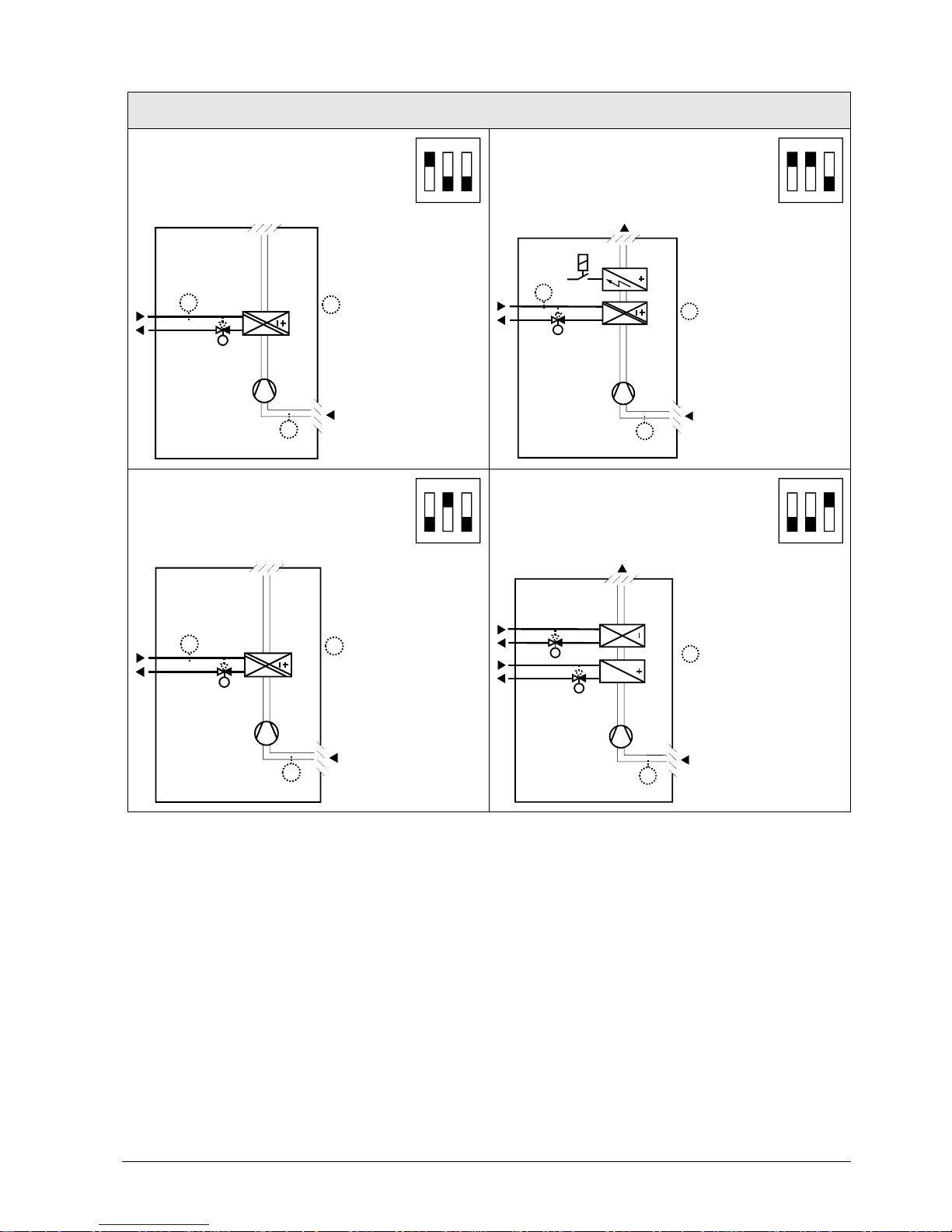
3.4.1 Applications for fan coil systems
Application and output signal, DIP switches, diagram
∂ 2-pipe fan coil unit ON/OFF
(heating or cooling)
1ON2 3
∂ 2-pipe fan coil unit with el. heater
(heating or cooling) ON/OFF
1ON2 3
30 7 6 D2 0
(B1)
M1
Y1
T
B2
T
T
(B1)
Y1
M1
3171D21
T
B2
YE
T
(B1)
T
(B1)
∂ 2-pipe fan coil unit 3-position
(heating or cooling)
1ON2 3
∂ 4-pipe fan coil unit ON/OFF
(heating and cooling)
∂
1ON2 3
30 7 6D 2 0
(B1)
M1
Y1
T
B2
T
T
(B1)
T
Y2
Y1
M1
3076D 22
(B1)
T
(B1)
Y1 Heating or heating/cooling valve
actuator
B1 Return air temperature sensor or external room
temperature sensor (optional)
Y2 Cooling valve actuator B2 Changeover sensor (optional)
YE Electric heater M1 1-speed or 3-speed fan*)
N1 Thermostat
Note : On RDF301 and RDF301.50, it is recommended that the fan is running in
deadzone, i.e. P60=0, or using a return air- or external temperature sensor.
Legend
 Loading...