

Page 1
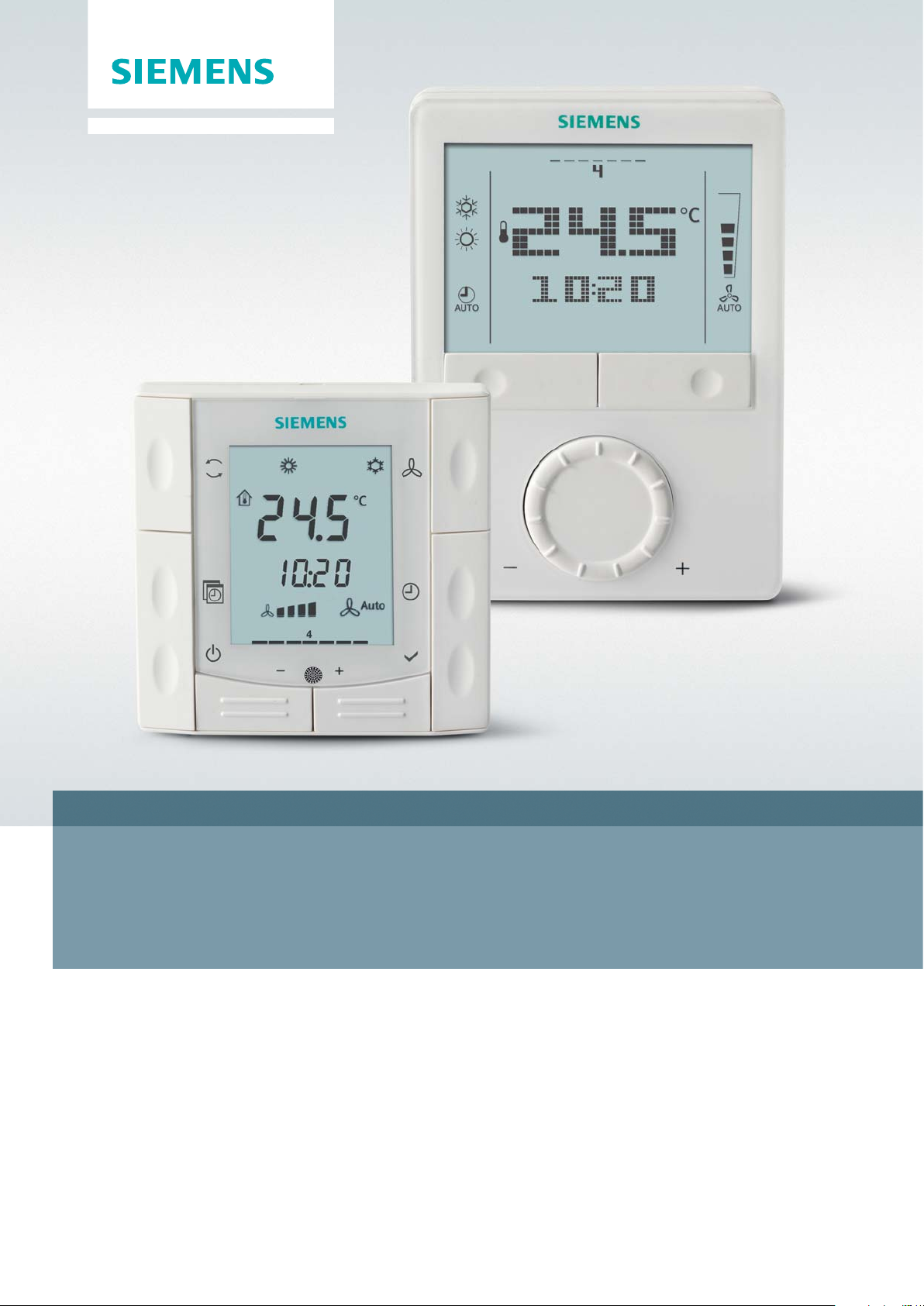
RDG/RDF – room thermostats
Application Guide
Answers for infrastructure.Answers for infrastructure.
Page 2
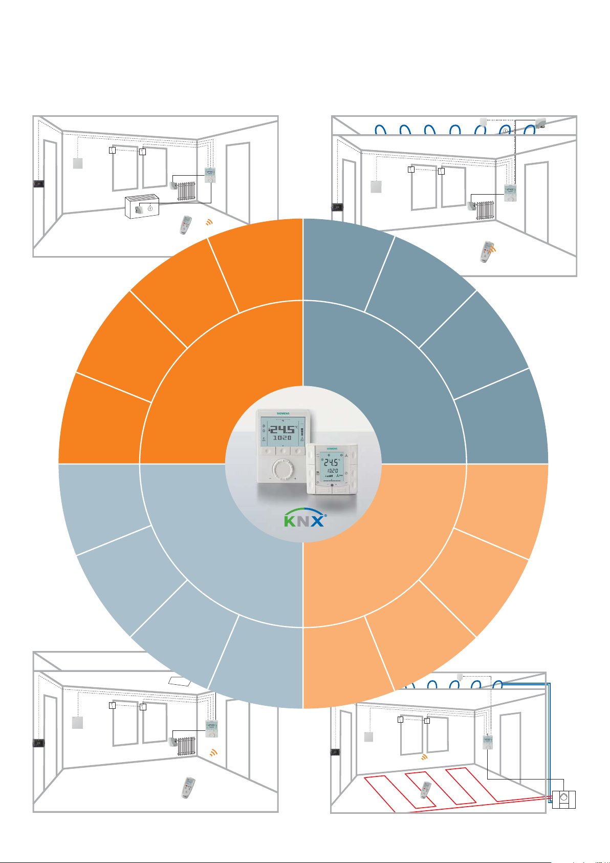
Application overview
2-pipe
2-stage
heating
or cooling
Single duct
Single duct
with el. heater
2-pipe
el. heater or
radiator
Fan coil unit
Variable air volume
(VAV)
4-pipe with
el. heater
Chilled/
heated ceiling
Chilled/heated
ceiling with
el. heater
Chilled/heated
ceiling and
radiator
Universal
Chilled
ceiling
and radiator
Compressor
for heating
or cooling
Heat pumps
Compressor
with el. heater
Single duct
and radiator
2
Single
duct with
heat/cool coil
2-stage
compressor
for heating
or cooling
Compressor
for heating
and cooling
Page 3

Contents
Introduction ................................................................................................................ 4
Before you start .........................................................................................................4
Description of RDG range ........................................................................................... 4
Product range RDG .................................................................................................... 4
Description of RDF.. semi fl ush-mount range ............................................................... 5
Product range RDF/RDU stand-alone ...........................................................................5
Product range RDF/RDU stand-alone with time program ..............................................5
Product range RDF/RDU with bus interface ..................................................................5
Description of applications ........................................................................................6
Extensive features and functions ............................................................................... 7
Fan coil – application overview ...................................................................................8
Fan coil – product overview ........................................................................................10
Universal – application overview ............................................................................ 12
Universal – product overview ................................................................................14
Heat pumps – application overview ..........................................................................15
Heat pumps – product overview ............................................................................... 16
VAV – application overview ...................................................................................... 18
VAV – product overview ........................................................................................... 19
How to prepare and set up your room thermostats ...................................................20
Introduction ...........................................................................................................20
Control parameters ................................................................................................. 20
Installation and set up .............................................................................................20
Application-specifi c parameters ................................................................................21
Communicating, KNX thermostats ...........................................................................22
Suggestions for energy saving ............................................................................... 22
FAQ ........................................................................................................................23
Reference to the basic documentation ......................................................................23
Application examples ..............................................................................................24
3
Page 4
Introduction
The RDG and RDF thermostat range is very versatile and includes a number of products.
RDG and RDF offer extensive features and cover a broad range of applications.
The document:
– provides you an overview of the new RDG and RDF ranges
– assists you in selecting the suitable product and
– provides helpful installation and commissioning information
The section “application overview” for each main application – i.e. fan coil unit
(FCU, universal, heat pumps and VAV – shows what applications are covered by
which thermostat line.
The sections “product overview” show the available thermostat variants and their
supported applications.
Before you start
We recommend proceeding as follows prior to selecting a thermostat:
– Type of main application: FCU, universal, heat pump or VAV
– Application: e.g. 2-pipe with electric heater
– Type of control output 1: ON/OFF, PWM, 3-position, or DC 0...10 V
– Type of control output 2: ON/OFF, PWM, 3-position, or DC 0…10 V
– Type of inputs: e.g. external room temperature sensor, changeover sensor,
keycard contact etc.
– Type of thermostat: stand-alone, stand-alone with 7-day timer, or communicating
thermostat
– Thermostat design: wall- or semi fl ush-mounted
– Other important requirements
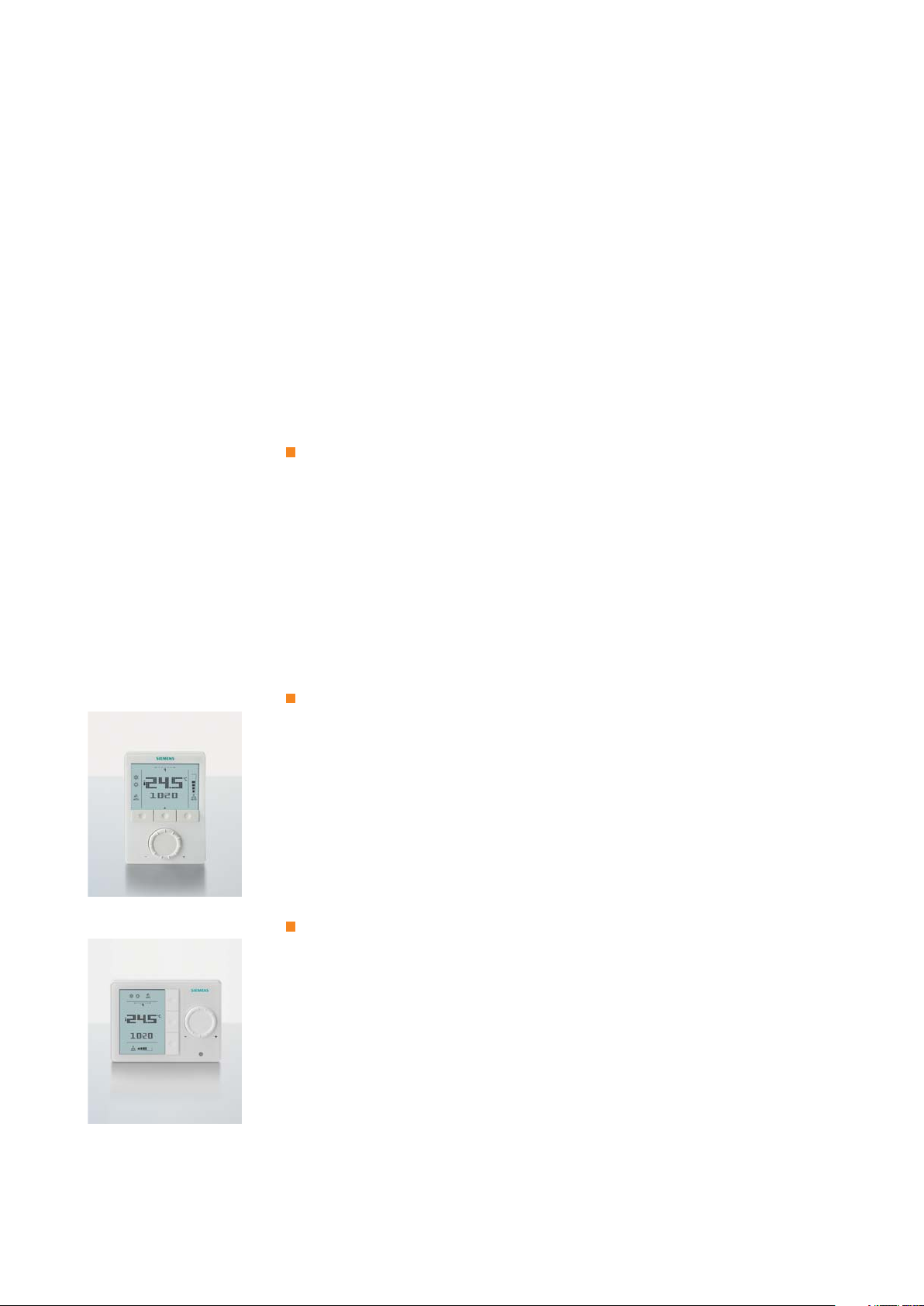
Description of RDG range
The RDG is a compact, wall-mounted version with an elegant and modern design.
The product consists of 2 lines of versatile products – RDG100 and RDG400:
– RDG100 line for FCUs plus universal (e.g. chilled ceilings or radiators)
and heat pump applications
– RDG400 line for VAV applications
The thermostats are available as stand-alone versions, stand-alone with 7-day program
and KNX versions tailored for use with Synco 700 via LTE-mode, for integration in Synco
living or BACS (Building Automation and Control System) via S-mode.
Product range RDG
– RDG100 – the versatile stand-alone thermostat with ON/OFF and modulating
(PWM or 3-position) outputs
– RDG100T – the versatile stand-alone thermostat with 7-day program and same
functionality as RDG100, plus infrared receiver for remote control
– RDG100T/H – the versatile stand-alone thermostat is the landscape version of RDG100T,
the 7-day program can be disabled
– RDG100KN – the versatile communicating thermostat with the same functionality as
RDG100, plus KNX interface
– RDG110 – the robust stand-alone thermostat with relay outputs (SPDT) for applications
with max. 5 A current on the control outputs. This thermostat is the ideal solution for
ON/OFF applications with electric heater, heat pumps, or heat pumps with reversing
valve (RV).
– RDG140 – the modulating thermostat operating on AC 24 V (SELV) with DC 0…10 V
control outputs
4
Page 5
– RDG160 – the energy-effi cient modulating thermostat to control electronic
commutated fan motors (ECM Fans), operating on AC 24 V (SELV) with DC 0...10 V
outputs for valve and fan
– RDG160KN – the communicating energy-effi cient modulating thermostat for control-
ling electronic commutated fan motors (EC Fans) and either DC or 2-position valves, or
for 3-speed fan and DC valves, including KNX interface
– RDG400 – the versatile stand-alone thermostat for VAV applications with modulating
and ON/OFF outputs
– RDG400KN – the versatile communicating thermostat with the same functionality as
RDG400, plus KNX interface
A number of control parameters can be adjusted on each thermostat to optimize the
control performance.
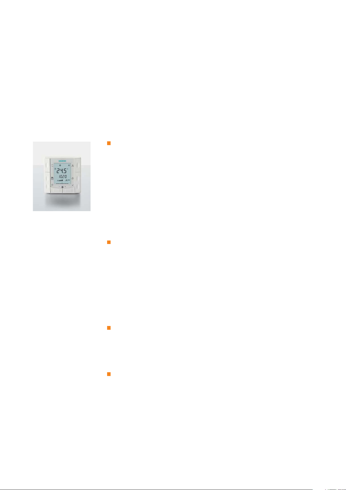
Description of RDF semi fl ush-mount range
The RDF.. range is a compact semi fl ush mount solution. The RDF6.. line fi ts
into round conduit boxes with a 60 mm diameter and a minimum 40 mm of depth. The
RDF3.. and RDF4.. lines are designed to fi t into conduit boxes with fi xing center 60.3 mm
(British standard BS4662).
The RDF and RDU are two product ranges featuring versatile and slim products:
– RDF range for FCUs and heat pump applications
– RDU range for VAV applications
The thermostats are available as stand-alone, stand-alone with 7-day program and KNX
versions tailored for use with Synco 700 via LTE-mode, for Synco living or for integration in
BACS via S-mode. There is also a version available with ModBus interface.
Product range RDF/RDU stand-alone
– RDF300 – the versatile stand-alone thermostat with ON/OFF or modulating 3-position
outputs
– RDF300.02 – also includes backlit display
– RDF340 – modulating thermostat operating on AC 24 V (SELV) with DC 0…10 V
control outputs
– RDF310.2 – basic stand-alone thermostat for 2-pipe applications
– RDF310.21– also offers a backlit display and infrared receiver for remote control
– RDF600 – versatile stand-alone thermostat for use with round conduit boxes
conforming to CEE/VDE with the same functionality as RDF300.02
– RDU340 – the versatile stand-alone thermostat for VAV applications with modulating
DC 0…10 V and ON/OFF outputs
RDF product range, stand-alone with time program
– RDF600T – the versatile stand-alone thermostat with 7-day program and same
functionality as RDF600, plus infrared receiver for remote control and backlit digital
display for use with round conduit boxes conforming to CEE/VDE
– RDF410.21 – basic stand-alone thermostat for 2-pipe applications, with 7-day program,
backlit digital display and infrared receiver for remote control
Product range RDF/RDU with bus interface
– RDF301 – communicating thermostat with the same functionality as RDF300,
plus KNX interface and backlit display
– RDF301.50 – communicating thermostat with the same functionality as RDF301,
plus switching groups for lighting and blind control via KNX S-mode
– RDF600KN – communicating thermostat for use with round conduit boxes
conforming to CEE/VDE with the same functionality as RDF301
– RDF302 – communicating thermostat with the same functionality as RDF300,
including ModBus interface
– RDU341 – communicating thermostat with the same functionality as RDU340,
plus KNX interface
5
Page 6
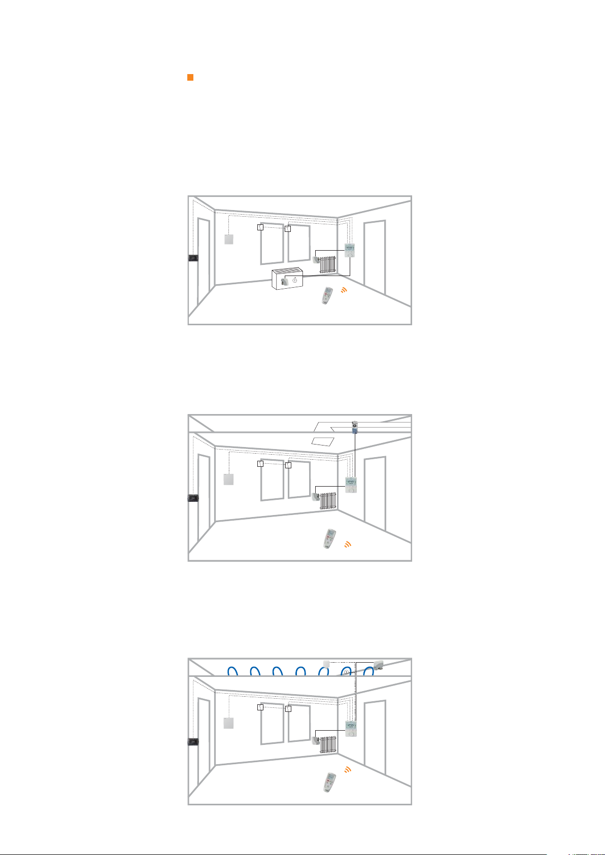
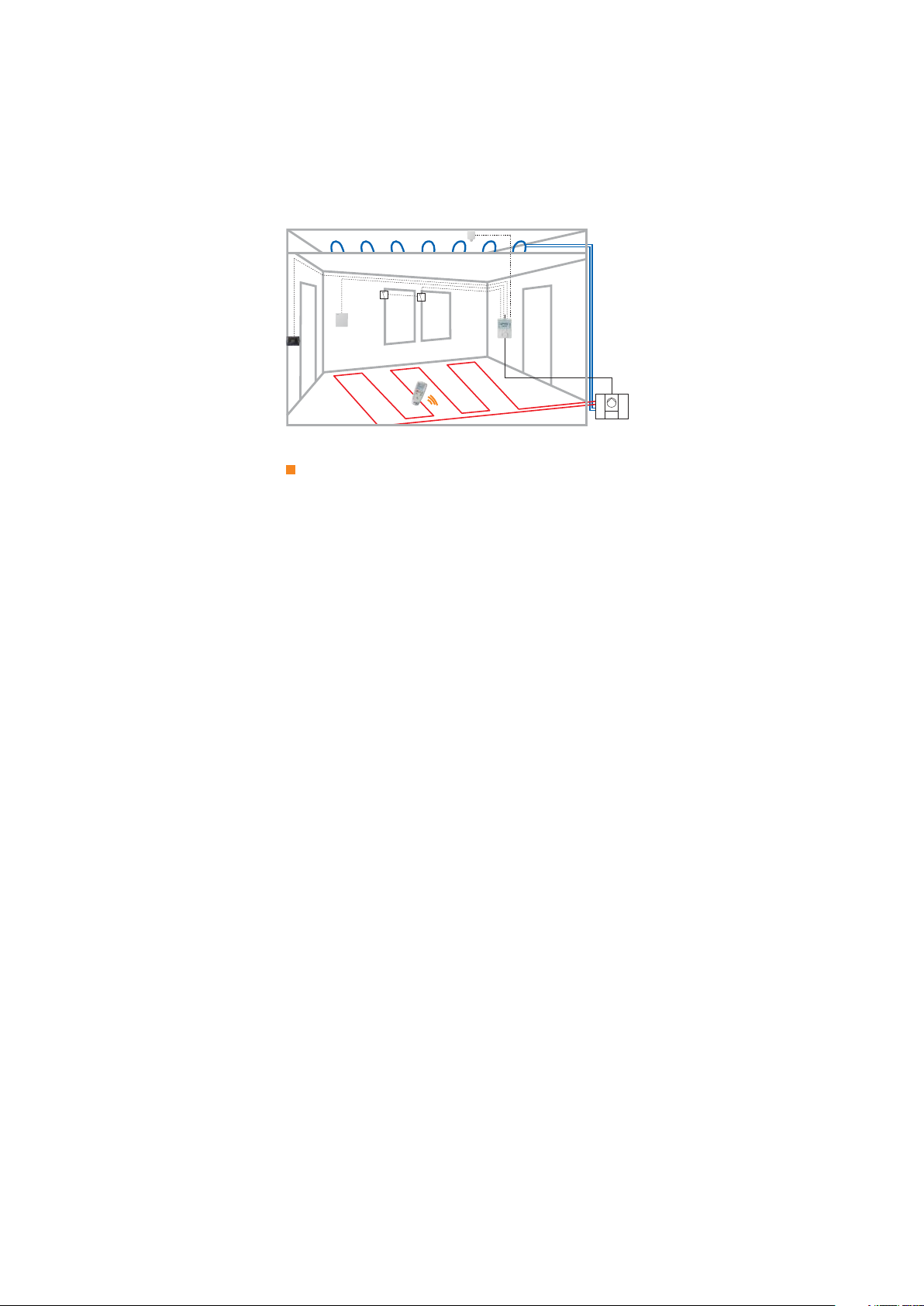
Description of applications
The RDG/RDF thermostats cover the following applications:
FCUs via ON/OFF or modulating control outputs:
– 2-pipe system
– 2-pipe system with electric heater
– 2-pipe system and radiator/fl oor heating
1
– 4-pipe system
– 4-pipe system with electric heater
– 2-stage heating or cooling system
1
1
VAV systems via ON/OFF or modulating control outputs:
– Single-duct system
– Single-duct system with electric heater
– Single-duct system and radiator/fl oor heating
– Single-duct system with heating/cooling coil
1
1
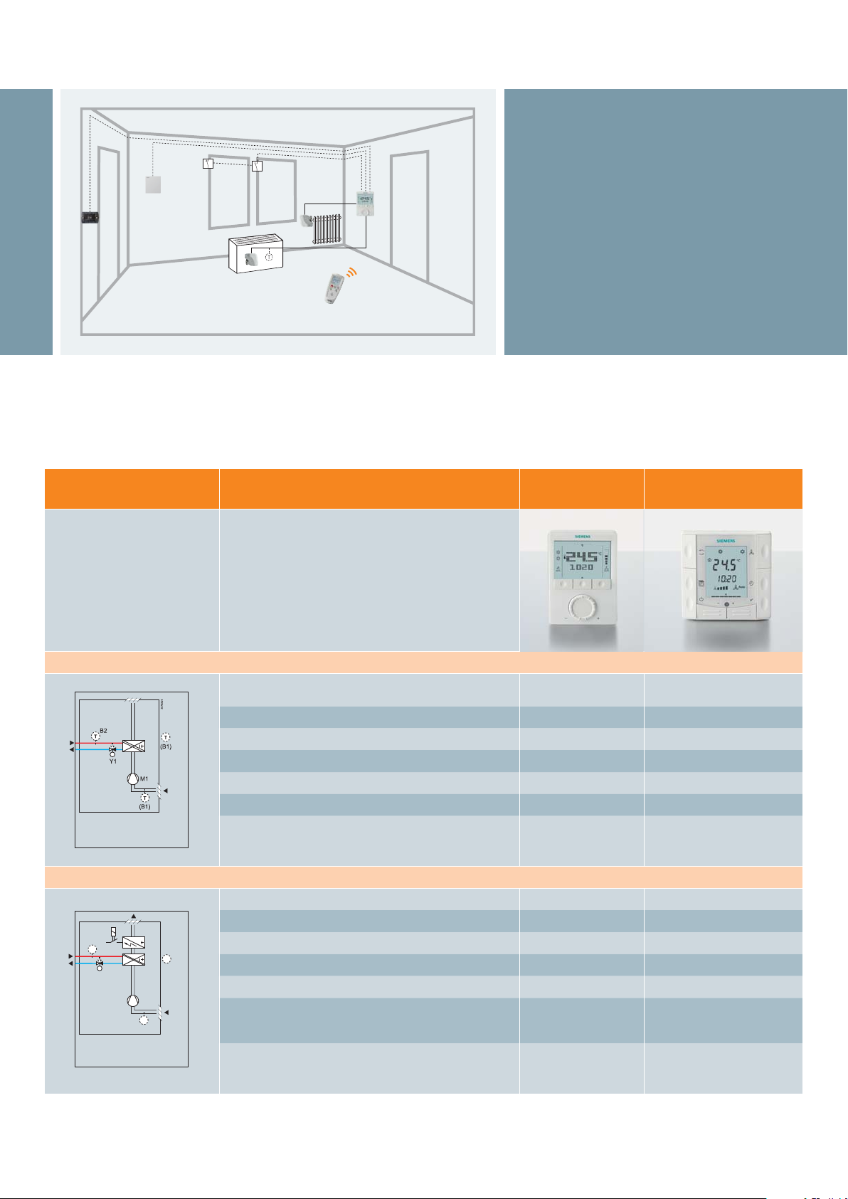
Chilled/heated ceilings (or radiators) via ON/OFF or modulating control outputs:
– Chilled/heated ceiling
– Chilled/heated ceiling with electric heater
– Chilled/heated ceiling and radiator/fl oor heating
– Chilled/heated ceiling, 2-stage heating or cooling
6
1
1
Page 7
Heat pumps with DX type equipment:
– 1-stage compressor for heating or cooling
– 1-stage compressor for heating or cooling with electric heater
– 1-stage compressor for heating or cooling and radiator/fl oor heating
– 1-stage compressor for heating and cooling with reversing valve
– 2-stage compressor for heating or cooling
1
1
1
The RDG/RDF offer extensive features and functions
2
– Operating mode: Comfort, Economy and Protection
– Energy saving functions: external operating mode switchover, 7-day program,
keycard or window contact, minimum and maximum setpoint limitation, etc.
– Numerous applications selectable via DIP switch
– Heating/cooling changeover: automatic or manual
– Control output signals: ON/OFF (triac or relay), PWM, 3-position and DC 0...10 V
3
– Fan control: automatic or manual fan speed for 1-speed, 3-speed or ECM
fan
– Fan operation: fan enable, heating only, cooling only, fan disable
– Multifunctional inputs: (function selectable)
– External temperature sensor
– Heating/cooling changeover sensor or switch
– Operating mode switchover for keycard, window or time switch contact
– Electric heater release
– Dew point monitor
– Fault input
– 7-day program
– Timer for prolonged presence and absence function
– Button lock
– Backlit display
– Infrared remote control
– Reminder for cleaning fan fi lter
– Floor temperature limitation function
– Various parameters for setpoint adjustment and control setting
– KNX communication interface: Synco700 via LTE mode,
Synco living and BACS (Building Automation and Control System) via S-mode
– Switching groups for lighting and blind control via KNX S-mode
– ModBus communication interface
1
Applications covered by RDG thermostats only
2
Feature availability depends on thermostat type
3
Electronic commutated motor, DC 0...10 V
7
Page 8
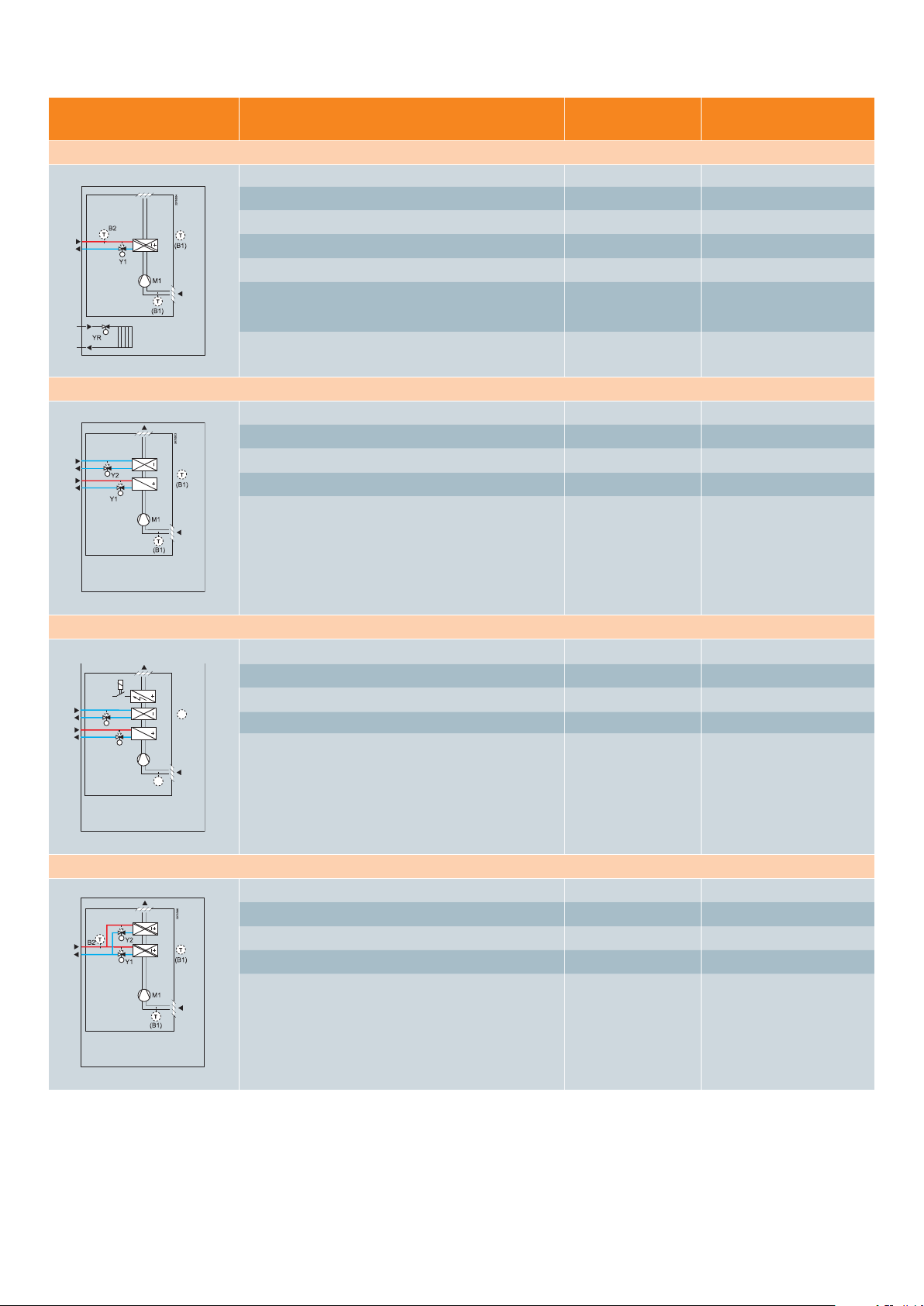
Application description
– Control sequences for heating and/or cooling,
1 or 2 stages
– Multifunctional inputs for keycard contact,
external sensor, etc.
– Automatic or manual heating/cooling changeover
– Automatic or manual fan speed
– 3-speed, 1-speed and mod. (ECM) fan control
(DC 0...10 V)
– Fan operation selectable in heating and cooling
mode (enable, disable, heating only or cooling only)
Fan coil – application overview
Application
2-pipe system
2-pipe system with el. heater
YE
B2
T
Y1
3076S02
T
(B1)
M1
T
(B1)
Type of control outputs
2-pipe (ON/OFF) RDG100.. RDG110 RDF300.. RDF310..
2-pipe mod. (PWM) RDG100..
2-pipe mod. (3-pos.) RDG100.. RDF300.. RDF600..
2-pipe mod. (DC 0...10 V) RDG140 RDG160KN RDF340
2-pipe mod. (DC 0...10 V) ECM fan control (DC 0...10 V) RDG160..
2-pipe (ON/OFF) ECM fan control (DC 0...10 V) RDG160KN
2-pipe (ON/OFF), with el. heater (ON/OFF) RDG100.. RDG110 RDF300.. RDF600..
2-pipe (ON/OFF), with el. heater (mod. PWM or 3-pos.) RDG100..
2-pipe mod. (PWM), with el. heater (ON/OFF, PWM or 3-pos.) RDG100..
2-pipe mod. (3-pos.), with el. heater (ON/OFF, PWM or 3-pos.) RDG100..
2-pipe mod. (DC 0...10 V), with el. heater (DC 0...10 V) RDG140 RDG160KN RDF340
2-pipe mod. (ON/OFF, DC 0...10 V), with el. heater
(ON/OFF, DC 0...10 V).
ECM fan control (DC 0...10 V)
RDG..
Wall-mounted range
RDG160..
Semi fl ush-mounted range
RDF..
RDF600.. RDF410..
8
Page 9
Application
2-pipe system and radiator heating
4-pipe system
Type of control outputs
RDG..
Wall-mounted range
Semi fl ush-mounted range
2-pipe (ON/OFF) and radiator (ON/OFF) RDG100.. RDG110
2-pipe (ON/OFF) and radiator (mod. PWM or 3-pos.) RDG100..
2-pipe mod. (PWM) and radiator (ON/OFF, PWM or 3-pos.) RDG100..
2-pipe mod. (3-pos.) and radiator (ON/OFF, PWM or 3-pos.) RDG100..
2-pipe mod. (DC 0...10 V) and radiator (DC 0...10 V) RDG140 RDG160KN
2-pipe mod. (ON/OFF, DC 0...10 V) and radiator
RDG160..
(ON/OFF, DC 0...10 V).
ECM fan control (DC 0...10 V)
4-pipe (ON/OFF) RDG100.. RDG110
RDF300.. RDF600..
4-pipe mod. (PWM) RDG100..
4-pipe mod. (3-pos.) RDG100..
4-pipe mod. (DC 0...10 V) RDG140 RDG160KN RDF340
4-pipe mod. (ON/OFF, DC 0...10 V).
RDG160..
ECM fan control (DC 0...10 V)
RDF..
4-pipe system with el. heater
YE
B2
Y2
Y1
3076S05
T
(B1)
M1
T
(B1)
2-stage, heating or cooling
4-pipe (ON/OFF) with el. heater (ON/OFF) RDG100..
4-pipe (ON/OFF and 3-pos.) with el. heater (ON/OFF) RDG100..
4-pipe mod. (PWM) with el. heater (ON/OFF) RDG100..
4-pipe mod. (PWM and 3-pos.) with el. heater (ON/OFF) RDG100..
2-stage (ON/OFF) heating or cooling RDG100.. RDG110
2-stage mod. (PWM) heating or cooling RDG100..
2-stage mod. (3-pos.) RDG100..
2-stage mod. (DC 0...10 V) RDG140 RDG160KN
2-stage mod. (ON/OFF, DC 0...10 V).
RDG160..
ECM fan control (ON/OFF, DC 0...10 V)
Abbreviations
ON/OFF: 2-position control
3-pos.: Modulating 3-position control signal
PWM: Pulse Width Modulation control signal
DC 0...10 V: Modulating DC 0...10 V control signal
ECM fan: Electronic Commutated Motor for fan, DC 0...10 V
el. heater: Electric heater
mod. output: Modulating output
9
Page 10

Fan coil – product overview
Product
Communicating
Application Stand-alone
Stand-alone
with
7-day
program
Communicating
RDG100…
Versatile thermostats with
control output signal (ON/OFF)
or mod. (PWM or 3-pos.)
RDG110
Robust thermostat with
relay outputs (SPDT) for
ON/OFF – control sequences
RDG140
Thermostat for mod. control
sequences with (DC 0...10 V)
output signals
RDG160..
Thermostat for mod. control
sequences with (DC 0...10 V)
output signals for valve and
fan control (ECM) DC 0...10 V
– 2-pipe (ON/OFF, PWM or 3-pos.)
– 2-pipe with electric heater
– FCU: (ON/OFF, PWM or 3-pos.)
– el. heater: (ON/OFF, PWM or 3-pos.)
– 2-pipe and radiator
– FCU: (ON/OFF, PWM or 3-pos.)
– radiator: (ON/OFF, PWM or 3-pos.)
– 4-pipe (ON/OFF, PWM and/or 3-pos.)
– 4-pipe with electric heater
– FCU: (ON/OFF, PWM and ON/OFF, PWM or 3-pos.)
– el. heater: (ON/OFF)
– 2-stage heating or cooling
– FCU: (ON/OFF, PWM or 3-pos.)
– 2-pipe (ON/OFF)
– 2-pipe (ON/OFF) with el. heater (ON/OFF)
– 2-pipe (ON/OFF) and radiator (ON/OFF)
– 4-pipe (ON/OFF)
– 2-stage (ON/OFF) heating or cooling
– 2-pipe (DC 0...10 V)
– 2-pipe (DC 0...10 V) with el. heater (DC 0...10 V)
– 2-pipe (DC 0...10 V) and radiator (DC 0...10 V)
– 4-pipe heating (DC 0...10 V) and cooling (DC 0...10 V)
– 2-stage (DC 0...10 V) heating or cooling
– 2-pipe (DC 0...10 V)
– 2-pipe (DC 0...10 V) with el. heater (DC 0...10 V)
– 2-pipe (DC 0...10 V) and radiator (DC 0...10 V)
– 4-pipe heating (DC 0...10 V) and cooling (DC 0…10 V)
– 2-stage (DC 0...10 V) heating or cooling
RDG100 RDG100T
RDG100T/H
RDG110
RDG140
RDG160
RDG100KN
(KNX)
RDG160KN
(KNX)
RDG160KN
Communicating thermostat for
mod. control sequences with
DC 0...10 V or ON/OFF output
signals for valve and fan control
DC 0...10 V (ECM), 1- or 3-speed
With ECM fan control (DC 0…10 V signal)
– 2-pipe (ON/OFF)
– 2-pipe (DC 0...10 V)
– 2-pipe (ON/OFF) with el. heater (ON/OFF)
– 2-pipe (DC 0...10 V) with el. heater (ON/OFF)
– 2-pipe (DC 0...10 V) with el. heater (DC 0...10 V)
– 2-pipe (ON/OFF) and radiator (ON/OFF)
– 2-pipe (DC 0...10 V) and radiator (ON/OFF)
– 2-pipe (DC 0...10 V) and radiator (DC 0...10 V)
– 4-pipe heating (ON/OFF) and cooling (ON/OFF)
– 4-pipe heating (DC 0...10 V) and cooling (DC 0…10 V)
– 2-stage (ON/OFF) heating or cooling
– 2-stage (DC 0...10 V) heating or cooling
With 3- or 1-speed fan
– 2-pipe (DC 0...10 V)
– 2-pipe (DC 0...10 V) with el. heater (DC 0...10 V)
– 2-pipe (DC 0...10 V) and radiator (DC 0...10 V)
– 4-pipe heating (DC 0...10 V) and cooling (DC 0…10 V)
– 2-stage (DC 0...10 V) heating or cooling
RDG160KN
(KNX)
10
Page 11

Product
Semi fl ush-mounted units: RDF
Application Stand-alone
Stand-alone
with
7-day
program
Communicating
RDF300..
Versatile thermostats with
relay ouputs: ON/OFF or 3-pos.
RDF310../410..*
Basic thermostats for 2-pipe
application
RDF340
Thermostat for mod. control
sequences with (DC 0...10 V)
output signals
RDF600..*
Thermostats for use with round
conduit boxes conforming to
CEE/VDE, with relay outputs:
ON/OFF or 3-pos.
*Variants
RDF300 Basic version
RDF300.02 Thermostat with backlit display
RDF301 Thermostat with KNX interface
RDF301.50
RDF310.2 Basic version
Communicating
4 buttons for lighting and blinds
– 2-pipe
– FCU: (ON/OFF or 3-pos.)
– 2-pipe (ON/OFF) with el. heater (ON/OFF)
– 4-pipe (ON/OFF)
– 2-pipe (ON/OFF)
– 2-pipe (DC 0...10 V)
– 2-pipe (DC 0...10 V) with el. heater (DC 0...10 V)
– 4-pipe heating (DC 0...10 V) and cooling (DC 0...10 V)
– 2-pipe
– FCU: (ON/OFF or 3-pos.)
– 2-pipe (ON/OFF) with el. heater (ON/OFF)
– 4-pipe (ON/OFF)
thermostat
with
RDF300.. RDF301..
(KNX)
RDF302
(ModBus)
RDF310.. RDF410.21
RDF340
RDF600 RDF600T RDF600KN
(KNX)
RDF310.21 Basic version with backlit display and infrared remote control
RDF410.21 Basic version with backlit display, 7-day program and infrared remote control
RDF600 Basic version for use with round conduit boxes
RDF600T Basic version with 7-day program
RDF600KN Communicating thermostat with KNX interface
RDF302 Communicating thermostat with ModBus interface
11
Page 12

Application description
– For heating and/or cooling applications with heated/chilled
ceiling or radiator
– Control sequences for heating and/or cooling, 1- or 2-stages
– Dew point monitoring
Multifunctional inputs for keycard contact, external sensor, etc.
–
– Automatic or manual heating/cooling changeover
Universal – application overview
Chilled/heated ceiling or radiator
Application
Chilled/heated ceiling with changeover
Chilled/heated ceiling and el. heater
Type of control outputs
Chilled/heated ceiling (ON/OFF)
Chilled/heated ceiling, mod. (PWM) RDG100..
Chilled/heated ceiling, mod. (3-pos.) RDG100..
Chilled/heated ceiling, mod. (DC 0...10 V) RDG140 RDG160..
Chilled/heated ceiling (ON/OFF) and el. heater (ON/OFF) RDG100.. RDG110
Chilled/heated ceiling (ON/OFF) and el. heater (mod. PWM or 3-pos.) RDG100..
Chilled/heated ceiling, mod. (PWM) and el. heater (ON/OFF, PWM or 3-pos.)
Chilled/heated ceiling, mod. (3-pos.) and el. heater (ON/OFF, PWM or 3-pos.) RDG100..
Chilled/heated ceiling, mod. (ON/OFF, DC 0...10 V) and el. heater
(ON/OFF, DC 0...10 V)
RDG…
Wall-mounted range
RDG100.. RDG110
RDG100..
RDG140 RDG160..
12
Page 13

Application
Chilled/heated ceiling and radiator
Chilled ceiling and radiator
Type of control outputs
Chilled/heated ceiling (ON/OFF) and radiator (ON/OFF)
Chilled/heated ceiling (ON/OFF) and radiator (mod. PWM or 3-pos.) RDG100..
Chilled/heated ceiling, mod. (PWM) and radiator (ON/OFF, PWM or 3-pos.) RDG100..
Chilled/heated ceiling, mod. (3-pos.) and radiator (ON/OFF, PWM or 3-pos.)
Chilled/heated ceiling, mod. (ON/OFF, DC 0...10 V) and radiator
(ON/OFF, DC 0...10 V)
Chilled ceiling (ON/OFF) and radiator (ON/OFF) RDG100.. RDG110
Chilled ceiling (ON/OFF) and radiator (mod. PWM or 3-pos.) RDG100..
Chilled ceiling (PWM) and radiator (ON/OFF, PWM or 3-pos.) RDG100..
Chilled ceiling (3-pos.) and radiator (ON/OFF, PWM or 3-pos.) RDG100..
Chilled ceiling (ON/OFF, DC 0...10 V) and radiator (ON/OFF, DC 0...10 V) RDG140 RDG160..
RDG…
Wall-mounted range
RDG100.. RDG110
RDG100..
RDG140 RDG160..
Chilled/heated ceiling with 2-stage cooling or 2-stage heating
2-stage (ON/OFF) heating or cooling RDG100.. RDG110
2-stage mod. (PWM) heating or cooling RDG100..
2-stage mod. (3-pos.) heating or cooling RDG100..
2-stage mod. (ON/OFF, DC 0...10 V) heating or cooling RDG140 RDG160..
Abbreviations
ON/OFF: 2-position control
3-pos.: Modulating 3-position control signal
PWM: Pulse Width Modulation
DC 0...10 V: Modulating DC 0...10 V control signal
el. heater: Electric heater
mod. output: Modulating output
13
Page 14

Universal – product overview
Product Application Stand-alone
Wall-mounted units: RDG
Stand-alone
with
7-day
program
Communicating
RDG100…
Versatile thermostats
with control outputs
signal ON/OFF or mod.
(PWM or 3-pos.)
RDG110
Thermostats with relay
outputs (SPDT) for (ON/OFF)
control sequences
RDG140
Thermostat for mod. control
sequences with
(DC 0...10 V) outputs signals
RDG160..
Thermostat for mod. control
sequences with
(DC 0...10 V) outputs signals
RDG160KN
Communicating thermostat for
mod. control sequences with
DC 0...10 V or ON/OFF output
signals for valves
– Chilled/heated ceiling (ON/OFF, PWM or 3-pos.)
– Chilled/heated ceiling and el. heater
– CLC: (ON/OFF, PWM or 3-pos.)
– el.heater: (ON/OFF, PWM or 3-pos.)
– Chilled/heated ceiling and radiator
– CLC: (ON/OFF, PWM or 3-pos.)
– radiator: (ON/OFF, PWM or 3-pos.)
– Chilled ceiling and radiator
– CLC: (ON/OFF, PWM or 3-pos.)
– radiator: (ON/OFF, PWM or 3-pos.)
– Chilled/heated ceiling 2-stage
– CLC: (ON/OFF, PWM and/or 3-pos.)
– Chilled/heated ceiling (ON/OFF)
– Chilled/heated ceiling (ON/OFF) and el. heater (ON/OFF)
– Chilled/heated ceiling (ON/OFF) and radiator (ON/OFF)
– Chilled ceiling (ON/OFF) and radiator (ON/OFF)
– Chilled/heated ceiling 2-stage (ON/OFF)
– Chilled/heated ceiling (DC 0...10 V)
– Chilled/heated ceiling (DC 0...10 V) and el. heater (DC 0...10 V)
– Chilled/heated ceiling (DC 0...10 V) and radiator (DC 0...10 V)
– Chilled ceiling (DC 0...10 V) and radiator (DC 0...10 V)
– Chilled/heated ceiling 2-stage (DC 0...10 V)
– Chilled/heated ceiling (DC 0...10 V)
– Chilled/heated ceiling (DC 0...10 V) and el. heater (DC 0...10 V)
– Chilled/heated ceiling (DC 0...10 V) and radiator (DC 0...10 V)
– Chilled ceiling (DC 0...10 V) and radiator (DC 0...10 V)
– Chilled/heated ceiling, 2-stage (DC 0...10 V)
– 2-pipe (ON/OFF)
– 2-pipe (DC 0...10 V)
– 2-pipe (ON/OFF) with el. heater (ON/OFF)
– 2-pipe (DC 0...10 V) with el. heater (ON/OFF)
– 2-pipe (DC 0...10 V) with el. heater (DC 0...10 V)
– 2-pipe (ON/OFF) and radiator (ON/OFF)
– 2-pipe (DC 0...10 V) and radiator (ON/OFF)
– 2-pipe (DC 0...10 V) and radiator (DC 0...10 V)
– 4-pipe heating (ON/OFF) and cooling (ON/OFF)
– 4-pipe heating (DC 0...10 V) and cooling (DC 0…10 V)
– 2-stage (ON/OFF) heating or cooling
– 2-stage (DC 0...10 V) heating or cooling
RDG100 RDG100T RDG100KN
(KNX)
RDG110
RDG140
RDG160 RDG160KN
(KNX)
RDG160KN
(KNX)
14
Page 15

Application description
– Control sequences for heating and/or cooling,
1- or 2-stage
– Dew point monitoring
– Multifunctional inputs for keycard, contact,
external sensor, etc.
Min. ON/OFF time for compressor short cycle protection
–
Heat pumps – application overview
Application
Compressor in DX-type equipment for heating or cooling
1-stage compressor (ON/OFF) RDG110 RDG160KN RDF300.. RDF310..
Compressor in DX-type equipment for heating or cooling, with el. heater
1-stage compressor (ON/OFF), with el. heater (ON/OFF) RDG110 RDG160KN RDF300.. RDF600..
Type of control outputs
RDG..
Wall-mounted range
RDF..
Semi fl ush-mounted range
RDF410.. RDF600..
15
Page 16

Application
Compressor in DX-type equipment heating and cooling
1-stage compressor (ON/OFF) for heating and cooling RDG110 RDG160KN RDF300.. RDF600..
1-stage compressor (ON/OFF) for heating and cooling
with reversing valve
Compressor in DX-type equipment, cooling or heating, 2-stage
2-stage compressor (ON/OFF) for heating or cooling RDG110 RDG160KN
Type of control outputs
RDG..
Wall-mounted range
RDG110
RDF..
Semi fl ush-mounted range
Abbreviation
ON/OFF: 2-position control
el. heater: Electric heater
16
Page 17

Heat pumps – product overview
Product Application Stand-alone
Wall-mounted units: RDG
Stand-alone
with
7-day
program
Communicating
RDG110
Thermostat with relay output
(SPDT) to ON/OFF control
sequences
RDF600..*
Thermostats for use with
round conduit boxes conforming to CEE/VDE, with
relay outputs: ON/OFF
Semi flush-mounted units: RDF
RDF300../400..*
Versatile thermostats with
relay ouputs: ON/OFF
RDF310..
Basic thermostats for
1-stage compressor
RDG160KN
Communicating thermostat
with relay output: ON/OFF
– 1-stage compressor (ON/OFF) for heating or cooling
– 1-stage compressor (ON/OFF), with el. heater (ON/OFF)
– 1-stage compressor (ON/OFF) for heating and cooling
– 1-stage compressor (ON/OFF) for heating and cooling
with reversing valve
– 2-stage compressor (ON/OFF) for heating or cooling
– 1-stage compressor (ON/OFF) for heating or cooling
– 1-stage compressor (ON/OFF), with el. heater (ON/OFF)
– 1-stage compressor (ON/OFF) for heating and cooling
– 1-stage compressor (ON/OFF) for heating or cooling
– 1-stage compressor (ON/OFF), with el. heater (ON/OFF)
– 1-stage compressor (ON/OFF) for heating and cooling
– 1-stage compressor(ON/OFF) for heating or cooling
– 1-stage compressor (ON/OFF) for heating or cooling
– 1-stage compressor (ON/OFF), with el. heater (ON/OFF)
– 1-stage compressor (ON/OFF) for heating and cooling
– 2-stage compressor (ON/OFF) for heating or cooling
RDG110
RDF600 RDF600T RDF600KN
(KNX)
RDF300..
RDF310.. RDF410..
RDG160KN
(KNX)
*Variants
RDF300 Basic version
RDF300.02 Thermostat with backlit display
RDF310.2 Basic version
RDF310.21 Basic thermostat with backlit display
and Infrared remote control
RDF410.21 Basic thermostat with backlit display, weekly time program
RDF600 Basic version
RDF600T Basic version with 7-day program
RDF600KN Communicating
and Infrared remote control
thermostat
with KNX interface
17
Page 18

Application description
– Control sequences for heating and/or cooling
– Modulating control output DC 0…10 V or 3-pos. for
VAV box/air fl ow controller
– Multifunctional inputs for keycard, contact,
external sensor, etc.
– Automatic or manual heating/cooling changeover
– Adjustable minimum and maximum limitation of
air fl ow signal (DC 0…10 V)
– Modulating PI control
– Output signal inversion as an option
VAV – application overview
Application
Single duct
Single duct with el. heater
M
V
YV
YE
Type of control outputs
Single duct (DC 0...10 V) for VAV-box RDG400..
Single duct mod. (3-pos.) for VAV-box RDG400..
Single duct (DC 0...10 V) for VAV-box,
with el. heater (ON/OFF)
3076S17
Single duct (DC 0...10 V) for VAV-box,
with el. heater (mod. PWM or 3-pos.)
Single duct (3-pos.) for VAV-box, with el. heater (DC 0...10 V) RDG400..
Wall-mounted range
RDG..
Semi fl ush-mounted range
RDU34..
RDG400.. RDU34..
RDG400..
RDF..
18
T
B1
Page 19

Application
Single duct with radiator
Single duct with heating/cooling coil
Type of control outputs
Single duct (DC 0...10 V) for VAV-box
with radiator (ON/OFF)
Single duct (DC 0...10 V) for VAV-box
with radiator (mod. PWM or 3-pos.)
Single duct (3-pos.) for VAV-box
with radiator (DC 0...10 V)
Single duct (DC 0...10 V) for VAV-box,
with heating/cooling coil (ON/OFF)
Single duct (DC 0...10 V) for VAV-box,
with heating/cooling (mod. PWM or 3-pos.)
Single duct (3-pos.) for VAV-box,
with heating/cooling (DC 0...10 V)
RDG..
Wall-mounted range
RDG400..
RDG400..
RDG400..
RDG400..
RDG400..
RDG400..
RDF..
Semi fl ush-mounted range
Abbreviations
VAV: Variable Air Volume system
ON/OFF: 2-position control
PWM: Pulse Width Modulation
DC 0...10 V: Modulating DC 0...10 V control signal
3-pos.: Modulating 3-position control signal
el. heater: Electric heater
mod. output: Modulating output
VAV – product overview
Product Application Stand-alone
Wall-mounted units: RDG
RDG400..
Versatile thermostats
with control outputs signal
DC 0...10 V, ON/OFF, PWM
or 3-pos.
– Single duct for VAV-box
– VAV: (DC 0…10 V or 3-pos.)
– Single duct for VAV-box with electric heater
– VAV: (DC 0…10 V) el. heater: (ON/OFF, PWM or 3-pos.)
– VAV: (3-pos.) el. heater: (DC 0…10 V)
– Single duct for VAV-box with radiator
– VAV: (DC 0…10 V) radiator: (ON/OFF, PWM or 3-pos.)
– VAV: (3-pos.) radiator: (DC 0…10 V)
– Single duct for VAV-box with heating/cooling coil
– VAV: (DC 0…10 V) coil: (ON/OFF, PWM or 3-pos.)
– VAV: (3-pos.) heating/cooling coil: (DC 0…10 V)
Stand-alone
with 7-day
Communicating
program
RDG400 RDG400KN
(KNX)
Semi fl ush-mounted units: RDU
RDU34..
Thermostats for mod. control
sequences with DC 0...10 V
and ON/OFF outputs signals
– Single duct (DC 0...10 V) for VAV-box
– Single duct (DC 0...10 V) for VAV-box with el. heater (ON/OFF)
RDU340 RDU341
(KNX)
19
Page 20

How to prepare and set up
your room thermostats
Introduction
The versatile RDG and RDF room thermostats help you to better meet your customer‘s needs.
The following information supports you in setting up your RDG and RDF thermostats.
Control parameters
A number of control parameters can be adjusted to optimize control performance and
enable additional functions, making it possible to employ. The RDG and RDF thermostats
in almost any type of application.
The control parameters are assigned to 2 levels:
– Service level and
– Expert level
The service level contains a small set of parameters to set up the thermostat for HVAC
systems (control sequence) and to adjust the user interface.
The expert level contains control parameters for fan, control inputs/outputs and other
functions. Take care when changing parameters on the expert level as these changes
impact the thermostat‘s control performance and functionality.
As a rule, you don´t need to adjust parameters once the required application is selected
TIP
via the DIP switch since the thermostat works correctly using factory set parameters. It may
be nevertheless necessary, in some cases, to adjust application specifi c parameters.
– Control sequence (P01): select heating/cooling sequence and
changeover function
– Multifunctional inputs (P38…P42): select the input functionality for X1, X2 and D1
– Control outputs (P46…P47): select type of output signal (ON/OFF, PWM, 3-pos.)
– Fan function (P52...P62): select fan functionality
TIP
Installation and set up
1. Select a suitable thermostat.
2. Set application via DIP switch as per mounting instructions.
3. Wire and install the thermostat. Apply power.
4. Set parameter P01 (control sequence) and other
application-specifi c parameters as needed.
Note: ARG71 – conduit box suitable for RDF3.. and RDF4.. semi fl ush-mount thermostats is
available as an accessory item.
20
Page 21

Control sequence (P01)
Application-specifi c parameter
This parameter is used to set the required heating and/or cooling sequence and to
select automatic/manual changeover. Parameter P01 is preset as follow, depending
on the selected application:
– 2-pipe or single-duct application: P01: = 1 = cooling only
– 4-pipe application: P01: = 4 = heating and cooling
Sequence
Multifunctional inputs
(X1, X2, D1)
Mode
Parameter
Heating only
P01=0
Cooling only
P01=1 P01=2 P01=3 P01=4
Manually select
heating or
cooling mode
Automatic
heating/cooling
changeover
Heating and
cooling mode
An NTC sensor of type NTC such as QAH11.1 (AI) or a switch (DI) can be connected to
the input terminals. Input functionality can be freely confi gured. The factory settings are
as follows:
RDG range RDF range
P38: Multifunctional input X1
P40: Multifunctional input X2
P42: Multifunctional input D1
External temperature sensor (1) Operating mode switchover (3)
Heating/cooling changeover (2) Heating/cooling changeover (2)
Operating mode switchover (3) N/A
Available function on X1, X2 and D1
Function of inputs Description
External/return air temperature (AI)
1
(not available for input D1)
2
Heating/cooling changeover (AI/DI) Automatic heating/cooling changeover sensor or switch
Temperature sensor input for
– External room temperature
– Return air temperature
– Floor temperature sensor to limit the heating output
Control outputs (P46…P47)
3
Operating mode switchover (DI) Digital input to switch the operating mode to Economy
4
Dew point monitor (DI) Digital input for a dew point sensor to monitor condensation
5
Enable electric heater (DI) Digital input to enable/disable the electric heater via remote control
6
Fault (DI)
7
Monitoring input (digital)
8
Monitoring input (temperature)
Digital input to signal a fault on the display (e.g. dirty air fi lter)
Digital input to monitor the state of an external switch via bus
(only for communicating variants)
Sensor input to monitor the state of an external sensor (e.g. QAH11.1)
via bus (only for communicating variants)
– The RDG100.. offers two control outputs, each of either type On/Off, PWM or 3-position.
To select the required type, use the DIP switch and P46 (1st control output) and/or P47
(2nd control output).
– The RDG400.. for VAV applications offers two control outputs, DC 0…10 V and either
ON/OFF, PWM or 3-position. To select the required type use the DIP switch and P46
(reheater/cooler control output) and/or P47 (damper actuator, DC 0...10 V or 3-pos.).
21
Page 22

Fan function
(P03, P52...P62, P67):
RDG and RDF offer an extensive fan control concept with a wide choice of functions and
features. The required options can be selected via the control parameters:
– Fan mode automatic-manual or manual only (P03)
– Fan active in cooling mode only, active in heating mode only, disable (P52)
– Control output for 3-speed/1-speed fan (P53)
– Control output for ECM fan, DC 0...10 V signal (P55…P57) on RDG160..
– Fan minimum on time (P59)
– Operation in dead zone for conjunction with return air sensor or to avoid damage
due to moisture (P60, P61)
– Fan start kick from standstill to overcome inertia and friction (P58)
– Fan overrun to avoid overtemperatures after the electric heater turned off (P54)
– Fan start delay by ON/OFF control to avoid cold or warm air (P67)
Note: Fan operation must be disabled via control parameter (P52) for universal application.
Parameters on
communi cating
thermostats
Diagnostic parameters
On communicating thermostats, control parameters can be downloaded via
ACS and ETS Service Tools.
Note: RDG/RDF require an external KNX bus power supply if connected via OCI700.
After installing and setting up the thermostat, you can check your confi guration by going
TIP
to the ”Expert” level and selecting the diagnostic parameters dxx (d01, d02, etc.).
Communicating, KNX thermostats
In connection with Synco 700, the communicating, KNX thermostats operate in LTE-mode.
The units are tailored as well for use with Synco living or for integration in BACS via S-mode.
Refer to technical documentation CE1N3127 for detailed information on installing and
commissioning a KNX system.
Suggestions for saving energy
TIP
– Use thermostats with 7-day program
– Use thermostats with modulating control outputs (e.g. DC 0...10 V or 3-position)
– Use thermostats with ECM fan control (DC 0...10 V)
– Use KNX communicating thermostats
– Activate auto fan function
– Connect external operating mode switchover for central operating mode control
– Connect window contacts to avoid energy losses when windows are open
– Connect keycard contact for switching the unit to Economy mode when rooms
are not occupied
– Defi ne optimum setpoint limitations (heating max. 20 °C, cooling min. 25 °C)
to minimize energy usage
– In application with electric heater, use function “Electric heater enable” (P38, P40...)
– Inform enduser of prolonged absences and presence function
22
Page 23

FAQ
Where are the DIP switches located?
On RDG, the DIP switches are located at the rear of the unit; on RDF semi fl ush-mount
thermostats, they are located on the inner side of the front panel.
Where do I fi nd the correct DIP switch position?
Refer to the Mounting Instructions and on the product.
How can I set the parameters?
The procedure for setting the parameters (service or expert level) is described
in the basic documentation of the thermostats.
When do I have to set the control parameters?
You generally do not need to adjust parameters since the unit works correctly using
the factory-set parameters. Nevertheless, in some rare cases, you may need to adjust
the application-specifi c parameters during commissioning to enable desired functions.
For that, access the expert level. Refer to technical documentation for detailed information.
The control parameters on the service level for HVAC systems and for adjusting the user
interface can be accessed at any time.
Is it possible to reload the default timer setting?
Yes. The default timer setting (A1… A8) and the procedure for reloading are described
in the technical documentation.
Is it possible to reset the control parameters?
Yes. The factory-set control parameters can be reloaded via parameter P71 by changing
the value to “ON” and by confi rming with the buttons. Refer to technical documentation
for detailed information.
Can the current settings and installation be checked?
On the expert level, some diagnostic parameters (d01, d02, etc.) are available
for checking the selected application, the status of the inputs and for testing the
3-position outputs. Refer to technical documentation for detailed information.
Reference to the basic documentation
– P3076: RDF3../6.. stand-alone thermostats for FCUs
– P3171: RDF3../6.. KNX communicating thermostats for FCUs
– P3181: RDG1.. stand-alone thermostats for FCUs
– P3191: RDG1..KN KNX communicating thermostats for FCUs
– P3182: RDG400 stand-alone thermostat for VAV
– P3192: RDG400KN KNX communicating thermostats for VAV
– P3078: RDU340 stand-alone thermostat for VAV
– P3172: RDU341 KNX communicating thermostat for VAV
– P3079: RDF302 ModBus communicating thermostat for FCUs
23
Page 24

Application examples
Installation and set up
1. Select a suitable thermostat.
2. Set application via DIP switch according to the mounting Instructions.
3. Wire and install the thermostat. Apply power.
4. If necessary, set parameter P01 (control sequence) and other application-specifi c parameters.
Fan coil application
examples
Application How to set the application
Fan coil unit, 2-pipe cooling only
– Valve actuator: ON/OFF
– Keycard contact
Fan coil unit, 2-pipe with el. heater
1. Thermostat: RDG100
2. DIP switch: 2-pipe application
Y1 = ON/OFF
3. Wiring: Actuator → Y1-N
Fan → Q1...Q3-N
Key card → D1-GND
4. Parameters: no change necessary (factory-setting)
TIPS
– Keycard contact in hotel guest rooms helps saving energy costs
– RDG100T with 7-day program
– RDG100KN communicating KNX
1. Thermostat: RDG110
2. DIP switch: 2-pipe application, el. heater
3. Wiring: Actuator → Y11-N
El. heater → Y21-N
Fan → Q1...Q3-N
Temp. sensor → X1-M
H/C changeover sensor → X2-M
4. Parameters: P01 = 3 (automatic H/C changeover)
– Valve actuator: ON/OFF
– Heating with electric heater ON/OFF
– Automatic changeover
– Return air temperature sensor
Fan coil, 4-pipe with el. heater
– Valve actuators H&C: PWM
– Electric heater: ON/OFF
– Electric heater enable input
– Window contact
TIPS
– RDG110 with relay outputs can drive direct an el. heater
up to 1 kW
1. Thermostat: RDG100
2. DIP switch: 4-pipe application, el. heater
Y1 = PWM
Y3 = PWM
3. Wiring: Actuator heating → Y1-N
Actuator cooling → Y3-N
Contactor
Fan → Q1...Q3-N
El. heater enable → X1-M
Window cont. → D1-GND
4. Parameters: P38 = 5 (El. heater Input)
P46 = 2 (PWM heating)
P47 = 2 (PWM cooling)
TIPS
– Electric heater enable signal for saving energy costs
– Note1: Add relay if load exceeds 1A!
1
for el. heater → Y2-N
24
Page 25

Application How to set the application
FCU, 2-pipe and fl oor heating, single speed
1. Thermostat: RDG100
2. DIP switch:
Y1 = ON/OFF
Y3 = ON/OFF
3. Wiring: Actuator cooling → Y1-N
Actuator heating → à Y3-N
Fan → Q1-N
Floor temperature sensor → X1-M
4. Parameters: P51 = 25 °C (fl oor Heat. Temp. limit)
P53 = 1 (single speed fan)
– 2-pipe, cooling only: ON/OFF
– Floor heating limitation (ON/OFF)
with temperature limitation
– Single speed fan
TIPS
– Limited heat supply to the fl oor to avoid overheating (DIN
EN 1264) thus protecting the fl oor and ensuring more comfort
– Select “2-pipe and el. heater” for application with electric
fl oor heating
FCU, 2-pipe with electric heater, ECM fans, thermostat with KNX
KNX
CE+ CE-
Y50L-Q2 Y10
L
N
1. Thermostat: RDG160KN
2. DIP switch: 2-pipe application, el. heater
Y10 = DC 0…10 V
Q2 = ON/OFF
3. Wiring: Actuator → Y10-Go
El. heater → Q2-N
ECM fan → Y50-Go
4. Parameters: No changes necessary (factory-setting)
TIPS
– Valve actuators (DC 0...10 V)
– Electric heater ON/OFF (relay)
– ECM fan (DC signal)
– Modulating (ECM) fan control for optimal comfort, lower level
of noise and energy costs saving
– Check ECM fan max. (P55) and min. (P56)
2-pipe application and radiator
Universal application
example
Chilled ceiling and radiator
– Chilled ceiling (3-pos.) and radiator (PWM)
– Dew point monitor
1. Thermostat: RDG100
2. DIP switch:
2-pipe application and radiator
Y1/Y2 = 3-pos.
Y3 = PWM
3. Wiring: Actuator cooling → Y1/Y2-N
Actuator heating → Y3-N
Dew point monitor → X1-M
4. Parameters: P38 = 4 (dew point input)
P46 = 2 (PWM)
P52 = 0 (fan disable)
TIP
– Dew point monitoring to detect condensation.
Cooling is stopped if condensation occurs.
25
Page 26

VAV application examples
Application How to set the application
VAV single duct, cooling only
1. Thermostat: RDG400
2. DIP switch: Single duct application
Y10 = DC 0...10 V
3. Wiring: Actuator → Y10-Go-G
Window contact → D1-GND
4. Parameters: no change (= default)
TIP
– Window contact for saving energy during the airing of rooms
– Damper actuator: 0…10 V
– Window contact
VAV single duct and el. reheater
Heat pump application
example
– Damper actuator: 3-pos.
– El. heater: DC 0...10 V
– Central time switch
Compressor with reversing valve
– Compressor: ON/OFF
– Reversing valve: ON/OFF
1. Thermostat: RDG400
2. DIP switch: Single duct application,
el. heater
Y10 = DC 0...10 V
3. Wiring: Actuator → Y1/Y2-G
El. heater → Y10-Go
Time switch → D1-GND
4. Parameters: P47 = 1 (VAV output 3-pos.)
TIPS
– Use a central time switch (e.g. SEH62.1) to set back room
temperature during non-business hours
– Adjust parameter “Prolong comfort period” (P68) to allow
occupant to override the central time switch, e.g. when
working overtime
1. Thermostat: RDG110
2. DIP switch: 4-pipe application
3. Wiring: Compressor → Y11/Y21-N
Reversing valve → Y12/Y22-N
4. Parameters: P52 = 0 (fan disable)
– Set control sequence to manual changeover (P01=2);
then the user can select manually between heating and cooling
26
Page 27

Notes
27
Page 28

Siemens Switzerland Ltd
Infrastructure & Cities Sector
Building Technologies Division
International Headquarters
Gubelstrasse 22
6301 Zug
Switzerland
Tel +41 41 724 24 24
Siemens Building Technologies
Infrastructure & Cities Sector
Brunel House
Sir William Siemens Square, Frimley
Camberley
Surrey, GU16 8QD
United Kingdom
Tel +44 1276 696000
Siemens Ltd
Infrastructure & Cities Sector
Building Technologies Division
22/F, AIA Kowloon Tower, Landmark East
100 How Ming Street
Kwun Tong, Hong Kong
Tel +852 2870 7888
The information in this document contains general descriptions of technical options available,
which do not always have to be present in individual cases. The required features should therefore
be specified in each individual case at the time of closing the contract.
© Siemens Switzerland Ltd, 2013 • Order no. 0-92173-en • 0,71306
Answers for infrastructure.
Our world is undergoing changes that force us to think
in new ways: demographic change, urbanization, global
warming and resource shortages. Maximum efficiency
has top priority – and not only where energy is concerned.
In addition, we need to increase comfort for the well-being
of users. Also, our need for safety and security is constantly
growing. For our customers, success is defined by how
well they manage these challenges. Siemens has the
answers.
“We are the trusted technology partner for
energy-efficient, safe and secure buildings and
infrastructure.”
www.siemens.com/thermostats
 Loading...