

Page 1
RDF20U
Technical Instructions
Document No. 155-334
September 27, 2007
Room Temperature Controller
with LCD for Two-Pipe Fan Coil
Units with Electric Heat
Siemens Industry, Inc.
Description
Room temperature controller with LCD for two-pipe fan coil units with electric heat.
Features
• Output for an on/off valve actuator
• Output for electric heat.
• Outputs for a three-speed fan.
• Control depending on the room or the return air temperature.
• Automatic heating/cooling changeover.
• Operating modes: Normal, Economy and Standby.
• Operating mode changeover input for remote control (Day/Night).
• Air movement control function for avoiding damage resulting from moisture.
• Selectable installation and control parameters.
• Display of room temperature or setpoint (selectable).
• Electronic minimum and maximum setpoint limits.
• Operating voltage 24 Vac.
Application
Typical use:
• Control of the room temperature in individual rooms that are heated or cooled with
two-pipe fan coil units equipped with electric heat.
• Opening or closing a valve.
• Switching electric heat.
• Switching a three-speed fan.
Suitable for two-pipe fan coil unit systems with:
• Automatic heating/cooling changeover.
• Continuous heating or cooling mode.
Product Number
RDF20U
Page 2
Technical Instructions RDF20U Room Temperature Controller with LCD
Document Number 155-334 for Two-Pipe Fan Coil Units with Electric Heat
September 27, 2007
Page 2 Siemens Industry, Inc.
Accessories
ARG70 Adapter plate for 4-inch × 4-inch or 2-inch × 4-inch conduit boxes
141-570 Lockable thermostat guard
QAH11.1 Changeover/remote temperature sensor
Warning/Caution
Notations
WARNING:
Personal injury or loss of life may occur if you do not perform
a procedure as specified.
CAUTION:
Equipment damage may occur if you do not follow a
procedure as specified.
Operation
The controller acquires the room temperature via its integrated sensor or optional
external return air temperature sensor (QAH11.1) and maintains the setpoint by
delivering two-position valve control and electric heat output commands.
The switching differential is 2 K (3.6F) in Heating mode and 1 K (1.8F) in Cooling
mode (adjustable).
Fan Operation
The fan is switched to the selected speed via control output 12, 11 or 10.
When the “Temperature-dependent fan control“ function is activated (can be selected
with DIP Switch No. 1), the fan is switched on/off depending on the temperature,
together with the valve.
It is switched off when any of the following occurs:
• leaving the heating or cooling sequence, provided the “Temperature-dependent fan
control“ function is activated.
• manually changing to Standby “ ” provided no setpoints (example, for freeze
protection) are set and active.
• activating an external operating mode changeover switch, provided application
conditions do not call for Economy mode.
• turning off the controller’s power supply.
NOTE: To avoid overheating the electric heat or to prevent the thermal cut-out from
responding, the fan will overrun for 60 seconds (default Parameter 21) when
the electric heat is switched off.
CAUTION:
In the event of failure, the RDF20U cannot protect the electric heat against
overheating. Therefore, the electric heat must be equipped with a separate
safety device (high temperature detection thermostat).
Display
If DIP Switch No. 2 is set to ON (factory setting), the controller displays the measured
room or return air temperature (unless parameters or setpoints are temporarily
changed). If the DIP switch is set to OFF, the controller displays the Normal operating
mode setpoint. In this case, the value of the current temperature reading can only be
visualized temporarily by selecting Parameter P14.
Page 3
RDF20U Room Temperature Controller with LCD Technical Instructions
For Two-Pipe Fan Coil Units with Electric Heat Document Number 155-334
September 27, 2007
Siemens Industry, Inc. Page 3
Water-based Fan Coil
Application
Use in conjunction with one valve, either for heating and/or cooling with changeover,
heating only or cooling only operation.
Heating Mode
Output terminals 4 and 2 (neutral) or 5 and 2 command the control valve.
Output terminals 4 and 2 are closed (24 Vac) when:
1. the measured room temperature is half the switching differential below the setpoint (W,
Heating mode), and
2. the valve has been closed for more than one minute (Parameter P20).
Output terminals 4 and 2 are open (0 Vac) when:
1. the measured room temperature is half the switching differential above the setpoint (W,
Heating mode), and
2. the valve has been closed for more than one minute (Parameter 19).
Cooling Mode
Output terminals 4 and 2 are open (0 Vac) when:
1. The measured room temperature is half the switching differential below the Cooling
mode setpoint (W), and
2. the valve has been closed for more than one minute (Parameter 20).
Output terminals 4 and 2 are closed (24 Vac) when:
1. the measured room temperature is half the switching differential above the Cooling
Mode setpoint (W), and
2. the valve has been open for more than one minute (Parameter 19).
NOTE: Terminal output 5 (NC) delivers a control command which is inverted to the
control command at output 4 (NO) and can be used for Normally Open
valves.
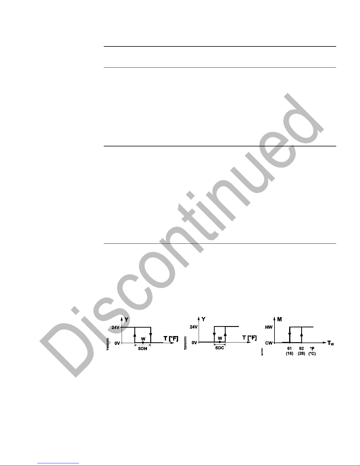
Automatic Changeover
The water temperature measured by the changeover sensor (QAH11.1) is used by the
controller to switch from Heating to Cooling mode, or vice versa. When the water
temperature rises above 82°F (28°C) (adjustable in Parameter P08), the controller
switches to Heating mode; below 61°F (16°C) (adjustable in Parameter P07) it switches
to Cooling mode. If, immediately after switching on, the water temperature is between
the two changeover points, the controller will start in Heating mode. The water
temperature is measured at 30-second intervals and the operating state is updated.
The value of the current temperature reading and the mode can be temporarily
displayed by selecting Parameter P15.
Figure 1. Heating Mode.
Figure 2. Cooling Mode.
Figure 3. Automatic
Changeover.
NOTE: Figures 1 and 2 show Output Terminal 4.
CW
HW
M
Cooling mode
Heating mode
Operating mode
SDH
SDC
Tw
Switching differential, Heating
Switching differential, Cooling
Water temperature
W
Y
T
Room temperature setpoint
Heating/cooling valve output
voltage
Room temperature
Page 4

Technical Instructions RDF20U Room Temperature Controller with LCD
Document Number 155-334 for Two-Pipe Fan Coil Units with Electric Heat
September 27, 2007
Page 4 Siemens Industry, Inc.
Automatic Changeover,
Continued
In systems without automatic changeover, the temperature sensor can be replaced by
an external switch (D1, GND) (must be suited for live voltage) for manual changeover.
In systems with continuous heating mode, no sensor will be connected to the
controller’s input. With continuous cooling mode, the controller (7/8) input must be
bridged.
Purging Function
(Optional)
The changeover sensor initiates the change from Heating to Cooling mode, based on
the measured water temperature. If a two-way valve is used, it is highly recommended
to activate the purging function (adjustable in Parameter P16). This function ensures
the correct acquisition of the medium temperature even if the two-way valve is closed
for a longer period of time. To achieve this, the valve is opened for one to five minutes
(adjustable in Parameter P16) at two-hour intervals during off hours.
When the purging function is activated, the first purging action is performed after
changing Parameter P16 and exiting the parameter setting mode.
Return Air Temperature
(Optional)
The RDF20U provides control based on the measured room temperature or the fan coil
unit’s return air temperature. It detects if a QAH11.1 cable temperature sensor is
connected to input 8-9 and then operates automatically according to that temperature.
Electric Heat, Active in
Heating Mode
NOTE: This function is not active when using thermal actuators.
In addition to hot water heating, the electric heat receives an ON command via output 6
when:
▪ the measured room temperature is x w − wD − 1/2 SDH, and
▪ the electric heat has been switched off for more than one minute.
The OFF command for the electric heat is given when:
1. the measured room temperature is x w − wD + 1/2 SDH, and
2. the electric heat has been switched on for more than one minute.
Electric Heat, Active in
Cooling Mode
For this operation, DIP Switch No. 4 must be set to ON (factory setting).
The electric heat receives the ON command via control output 6 when:
1. the measured room temperature is half the switching differential below the adjusted
setpoint, and
2. the electric heat has been switched off for more than one minute.
The OFF command for the electric heat is given when:
1. the measured room temperature is half the switching differential above the adjusted
setpoint, and
2. the electric heat has been switched on for more than one minute.
Page 5

RDF20U Room Temperature Controller with LCD Technical Instructions
For Two-Pipe Fan Coil Units with Electric Heat Document Number 155-334
September 27, 2007
Siemens Industry, Inc. Page 5
Application Diagrams
Figure 4. Heating Mode (Hot Water Plus
Electric Heat).
Figure 5. Cooling Mode with Optional
Electric Heat
(DIP Switch 4: ON, Electric Heat
Enabled)).
Figure 6. Cooling Mode (Chilled Water)
(DIP Switch 4: OFF, Electric Heat
Disabled).
T[°F] Room temperature
w Room temperature setpoint
wD Setpoint differential
Y Heating/cooling valve output
voltage
E Electric heat
SDH Switching differential, Heating
SDC Switching differential, Cooling
Xdz Dead zone
Page 6

Technical Instructions RDF20U Room Temperature Controller with LCD
Document Number 155-334 for Two-Pipe Fan Coil Units with Electric Heat
September 27, 2007
Page 6 Siemens Industry, Inc.
Operating Modes
Normal Mode
Heating or Cooling mode with automatic changeover and manually selected fan speed
(III, II or I). In Normal mode, the controller maintains the adjusted setpoint.
Economy Mode
A potential-free operating mode changeover switch can be connected to status input
D1-GND. When the switch closes its contact (due to an open window, for instance), the
operating mode will change from Normal to Economy. In this operating mode, the
relevant setpoints of heating or cooling are maintained (adjustable in Parameters P01
[setback temperature for heating] and P02 [setback temperature for cooling]). The
operating action of the switch (NC or NO) can be selected.
Standby
The relevant setpoints of heating and cooling are maintained when in Standby mode,
provided those setpoints have been adjusted. The standby temperature setting for
Heating mode in Parameter P03 is adjustable from 41°F to 68°F (5°C to 20°C) or “OFF”
and the setting for Cooling mode in Parameter P04 is adjustable from 70°F to 95°F
(21°C to 35°C) or OFF.
Avoiding Damage Due to
Moisture (continuous
fan)
To avoid damage due to moisture in very warm and humid climates resulting from lack
of air circulation in Economy mode (for example, in hotel rooms during unoccupied
periods), the fan can be kept running in Economy mode when activating Parameter
P17. In this case, the fan keeps running at the selected speed or at speed I if the
operating mode selector is in Standby “ ”.
Setting the Control
Parameters
A number of control parameters can be set to optimize control performance. These
parameters can also be set during operation without opening the unit. In the event of a
power failure, all set control parameters will be maintained.
Settings
The parameters can be changed as follows:
1. Set the operating mode selector to Standby “ ”.
2. Press buttons "+" and "–" simultaneously for a minimum of three seconds. Release
them and, within two seconds, press the "+" button again for three seconds. The
display will show P01.
3. Select the required parameter by repeatedly pressing the "+" and "–" buttons:
4. Press buttons "+" and "–" simultaneously; the current value of the selected
parameter appears, and can be changed by repeatedly pressing the "+" and "–"
buttons.
5. Press buttons "+" and "–" simultaneously again or five seconds after the last press
of a button. The last parameter will be displayed again.
6. To display and change additional parameters, repeat steps 3 through 5.
7. All changes will be stored and the controller returns to Normal operation 10
seconds after the last display or setting.
Page 7

RDF20U Room Temperature Controller with LCD Technical Instructions
For Two-Pipe Fan Coil Units with Electric Heat Document Number 155-334
September 27, 2007
Siemens Industry, Inc. Page 7
Table 1. Control Parameters.
Para-
meter
Description
Setting Range
Factory
Setting
P01
Heating setpoint in Economy mode
(operating mode changeover contact activated )
OFF,
41F to 68F (5C to 20C) (in increments of 0.5 K)
61F
(16C)
P02
Cooling setpoint in Economy mode
(operating mode changeover contact activated )
OFF,
70F to 95F (21C to 35C) (in increments of 0.5 K)
82F
(28C)
P03
Heating setpoint in Standby
OFF,
41F to 68F (5C to 20C) (in increments of 0.5 K)
46F (8C)
P04
Cooling setpoint in Standby
OFF,
70F to 95F (21C to 35C) (in increments of 0.5 K)
OFF
P05
Minimum setpoint limit stops in Normal mode
41F to 68F (5C to 20C) (in increments of 0.5 K)
41F (5°C)
P06
Maximum setpoint limit stops in Normal mode
70F to 95F (21C to 35C) (in increments of 0.5 K)
95F
(35°C)
P07
Heating/cooling changeover cooling switching
point
50F to 77F (10°C to 25°C) (in increments of 0.5 K)
61F
(16C)
P08
Heating/cooling changeover heating switching
point
8°F to 104°F (27°C to 40° C) (in increments of
0.5 K)
82F
(28C)
P09
Sensor calibration
-3K to 3 K (-5.4°F to 5.4°F) (in increments of 0.5 K)
0 K (0F)
P10
P-band in Heating mode or switching differential
heating. NOTE: This parameter is in degrees
Kelvin, 1 K = 1.8F.
0.5 K to 4 K (1°F to 7°F) (in increments of 0.5 K)
2 K
(3.6°F)
P11
P-band in Cooling mode or switching differential
cooling. NOTE: This parameter is in degrees
Kelvin, 1 K = 1.8F.
0.5 K to 4 K (1°F to 7°F) (in increments of 0.5 K)
1 K
(1.8°F)
P12
Dead zone in Normal mode
0.5 K to 10 K (1°F to 18°F) (in increments of 0.5 K)
2 K
(3.6°F)
P13
Active temperature sensor (no setting, display
only)
1: Room temperature sensor active
2: Return air temperature sensor active
--
P14
Value of current room temperature reading
(no setting, display only)
32°F to 120°F (0°C to 49°C) = current temperature
value
--
P15
Value of current heating/cooling changeover
temperature reading including indication of
current mode ( , ) (no setting, display only)
100 = input open (no sensor connected, heating
mode ( )
32°F to 120°F (0°C to 49°C) = current temperature
value
00 = input bridged, Cooling mode ( )
--
P16
Purging function
0 min.: Not active
1 to 5 min.: Active with selected duration
0 min.
P17
Fan control in Economy mode
OFF: Fan is off in the dead zone
ON: Fan is on in the dead zone,
ON: Running at the selected speed or at speed 1 if
in Standby
OFF
P18
Setpoint differential
0.5 K to 5 K (1°F to 9°F)
2 K
(3.6°F)
P19
Minimum output on time (4, 6)
1 to 20 minutes (in increments of 1 min.)
1 min.
P20
Minimum output off time (4, 6)
1 to 20 minutes (in increments of 1 min.)
1 min.
P21
Fan overrun
0 to 300 seconds (in increments of 10 seconds)
60 s
P22
Point of reference for setpoint in Normal mode
HA: Heating sequence; CL: Cooling sequence
HA
P23
Display unit of measure
°F, °C
°F
Page 8

Technical Instructions RDF20U Room Temperature Controller with LCD
Document Number 155-334 for Two-Pipe Fan Coil Units with Electric Heat
September 27, 2007
Page 8 Siemens Industry, Inc.
Ordering
The QAH11.1 temperature sensor can be used as a return air temperature or
changeover sensor. The changeover sensor and the valves must be ordered
separately.
Equipment
Combinations
Table 2.
Product Number
Description
Technical Instructions
QAH11.1
Temperature Sensor
155-329P25
599 Series
Two-way and Three-way
Zone Valves
155-320P25
SF Series
Zone Valve Actuator
155-321P25
Mechanical Design
The controller consists of two parts:
▪ Plastic housing which accommodates the electronics, the operating elements and
the built-in room temperature sensor
▪ Base
The housing engages in the base and is secured with two screws. The base carries the
screw terminals. The DIP switches are located at the rear of the housing.
Setting and Operating
Elements
Figure 7. RDF20U Components.
1
Display of the room temperature, setpoints or control parameters
2
Symbol used when displaying the current room temperature
3
Normal mode
Economy mode
4
Cooling valve open
Fan on
Heating valve open
5
Buttons for adjusting the setpoints and the control parameters
6
Operating mode selector
(Standby “ ”, Heating or Cooling mode with manual selection of fan speed)
Page 9

RDF20U Room Temperature Controller with LCD Technical Instructions
For Two-Pipe Fan Coil Units with Electric Heat Document Number 155-334
September 27, 2007
Siemens Industry, Inc. Page 9
Table 3. DIP Switches.
DIP Switch
No.
Description
Position ON (Factory Setting)
Position OFF
1
Fan control
Fan control is temperatureindependent
Fan control is temperaturedependent
2
Display of temperature or setpoint
Room (or return air) temperature
display
Setpoint display
3
Operating action of switch for external
operating mode changeover
Changeover activated when switch is
closed (NO)
Changeover activated when
switch is open (NC)
4
Electric heat
Active in Cooling mode
Inactive in Cooling mode
Engineering Notes
With the RDF20U, the controller input for automatic heating/cooling changeover can
also be used without the QAH11.1 cable temperature sensor:
▪ In systems without automatic changeover, the temperature sensor can be replaced
by an external switch (suited for live voltage) for manual changeover.
▪ In systems with continuous heating mode, no sensor is connected to the
controller’s input.
▪ In systems with continuous cooling mode, the controller input (7-8) must be
bridged.
Mounting,
Installation and
Commissioning
Notes
▪ Mounting location: On a wall or inside the fan coil unit.
▪ Do not mount in niches or bookshelves, behind curtains, above or near heat
sources.
▪ Do not mount in direct sunlight.
▪ Mounting height is approximately 60 inches (1.5 m) above the floor.
▪ The connecting wires can be run to the controller from a recessed conduit box.
Figure 8. Acceptable Mounting Height in Inches.
▪ Check the positions of the DIP switches and change them, if required.
▪ After applying power, the controller makes a reset during which all LCD segments
flash, indicating that the reset has been correctly made. This takes about three
seconds. Then, the controller is ready to operate.
▪ Prior to installing the changeover sensor, thermal conductive paste must be applied
to the location on the pipe where the sensor is placed.
Page 10

Technical Instructions RDF20U Room Temperature Controller with LCD
Document Number 155-334 for Two-Pipe Fan Coil Units with Electric Heat
September 27, 2007
Page 10 Siemens Industry, Inc.
Mounting,
Installation and
Commissioning
Notes, Continued
▪ Installation Instructions are included with the controller.
WARNING:
• Sensor inputs 7, 8, and 9 carry live voltage potential. If the sensor’s
cables must be extended, the cables used must be suited for live
voltage.
• The cables used must meet the insulation requirements for live
voltage.
Calibrating the Sensor
If the room temperature displayed by the controller is inconsistent with the room
temperature being measured, the temperature sensor of the RDF20U can be
recalibrated. To recalibrate, change Parameter P09.
Specifications
Power Supply
Operating voltage 24 Vac, +20/-25%
Frequency 50/60 Hz
Power consumption 6 VA maximum
Fan control outputs 12, 11, 10-N 24 Vac
Rating 5 (3) A maximum
Valve control output 4-2 (NO) 24 Vac
Rating 5 (3) A maximum
Valve control output 5-2 (NC 24 Vac
Rating 5 (3) A maximum
Electric heat control output 6-2 (NO) 24 Vac
Rating 5 (3) A maximum
Return air temperature sensor QAH11.1 safety class II
status input 9-8 NTC resistor 3K at 77°F (25°C)
Changeover—status input 7-8 QAH11.1, safety class II
NTC resistor 3K at 77°F (25°C)
Status input D1 and GND
Contact sensing SELV 6 to 15 Vdc/ 3 to 6 mA
Insulation against live voltage 4 kV, reinforced insulation
Operating action Selectable (NO/NC)
Permissible cable length with copper 262 ft (80 m)
cable 14 AWG for connection to terminals
7, 8, and 9 and D1, GND.
Operational Data
Setpoint setting range 41°F to 95°F (5°C to 35°C)
Control deviation at 77°F (25°C) + 1°F (0.5K) maximum
Switching differential in Heating mode, 2 K (3.6°F)
adjustable
Switching differential in Cooling mode, 1 K (1.8°F)
adjustable
Dead zone Xdz in Normal operation, 2 K (3.6°F)
adjustable
Setpoint differential WD, adjustable 2 K (3.6°F)
Setpoint, Economy mode , heating, 61°F (16°C)
adjustable
Setpoint, Economy mode , cooling, 82°F (28°C)
adjustable
Setpoint, Standby , heating, adjustable 46°F (8°C)
Setpoint, Standby , cooling, adjustable OFF
Page 11

RDF20U Room Temperature Controller with LCD Technical Instructions
For Two-Pipe Fan Coil Units with Electric Heat Document Number 155-334
September 27, 2007
Siemens Industry, Inc. Page 11
Specifications,
Continued
Environmental Conditions
Operation
Temperature 32°F to 122°F (0°C to 50°C)
Humidity <95% rh
Transport and storage
Temperature -13°F to 158°F (-25°C to 70°C)
Humidity <95% rh
Agency Approvals
UL Listing UL 873
General
Connection terminals Solid wires or prepared stranded
wires 2 × 16 AWG or 1 × 14 AWG
Weight 0.55 lb (0.25 kg)
Housing front color White (RAL 9003)
Wiring Terminals
Figure 9. Wiring Terminals.
1, 2 24 Vac, negative
3 24 Vac, positive
9 Return air temperature
sensor
8 Measuring neutral
7 Changeover sensor
D1,GND Potential-free operating mode
changeover switch (operating action
can be selected)
12 Control output, Fan speed I, 24 Vac
11 Control output, Fan speed II, 24 Vac
10 Control output, Fan speed III, 24 Vac
4 Control output, Valve 24 Vac
5 Control output, Valve 24 Vac
6 Control output, Electric heat 24 Vac
Wiring Diagrams
Figure 10. Two-Pipe Fan Coil Units with
Electric Heat.
B1 Return air temperature sensor
(QAH11.1)
B2 Changeover sensor (temperature
sensor QAH11.1)
E1 Electric heat
M1 3-speed fan
N1 Room temperature controller
RDF20U
S1 External operating mode
changeover switch
SN 24 Vac, negative
SP 24 Vac, positive
Y1 Zone valve
Page 12

Information in this publication is based on current specifications. The company reserves the right to make changes in specifications and models as
design improvements are introduced. Product or company names mentioned herein may be the trademarks of their respective owners.
© 2007 Siemens Industry, Inc.
Siemens Industry, Inc.
Building Technologies Division
1000 Deerfield Parkway
Buffalo Grove, IL 60089
+ 1 847-215-1000
Your feedback is important to us. If you have comments
about this document, please send them to
SBT_technical.editor.us.sbt@siemens.com
Document No. 155-334
Printed in the USA
Page 12
Dimensions
In Inches
(Millimeters)
Figure 11. RDF20U Controller.
Figure 12. Base Plate.
 Loading...