

Page 1
N3057en
2014
-10-28
Building Tech
nologies
3
057
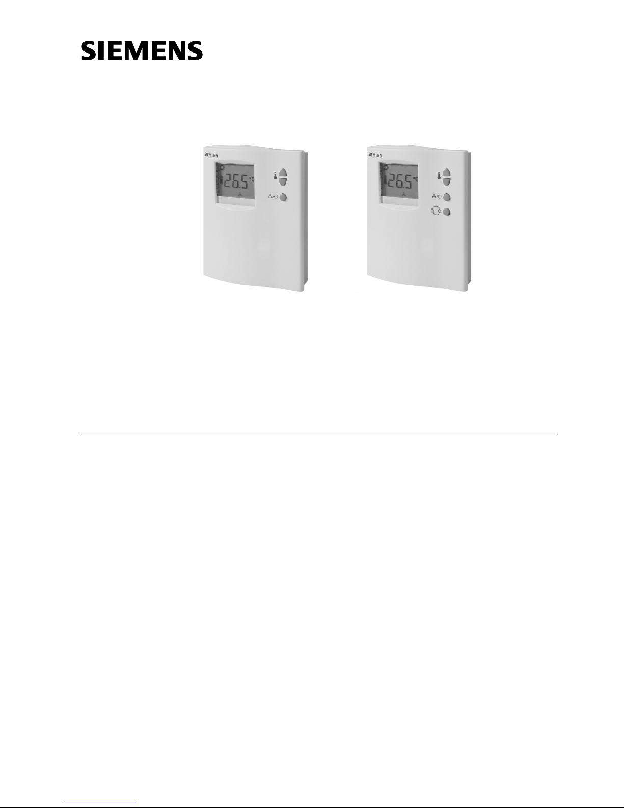
RDF110
RDF110.2
RDF110/IR
RDF110.2/IR
Room Temperature
Controllers with LCD
RDF110…
for 2
-pipe fan coil units
for compressors in
DX type equipment
Output for on / off valve actuator or 1-stage compressor
3-speed fan control: Automatic or manual
Adjustable commissioning and control parameters
Optional display of room temperature or setpoint
Minimum and maximum setpoint limitation
Operating voltage AC 230 V
Additional features of RDF110
Automatic heating / cooling changeover
Operating modes: Normal operation, Economy (Energy saving) and Protection
(Standby)
Input for heating / cooling changeover or return air temperature sensor
Potential-free input for operating mode changeover (key card contact, etc.)
Function for avoiding damage resulting from moisture
Additional features of RDF110.2
Manual heating / cooling changeover
Operating modes: Normal operation, Protection (Standby)
Optional
Infrared remote control (RDF110/IR, RDF110.2/IR)
Page 2
2/14
Siemens Room Temperature Controllers N3057en
Building Technologies 2014-10-28
Use
For controlling the room temperature in individual rooms and zones that are
• heated or cooled with 2-pipe fan coil units
• cooled with a single compressor in DX type equipment
The controller controls
• a 3-speed fan
• either a valve actuator in a 2-pipe system, or
• a 1-stage compressor in DX type equipment
Suitable for use in systems with
• automatic heating / cooling changeover (RDF110)
• continuous heating or cooling mode (RDF110)
• manual heating / cooling changeover (RDF110.2)
Functions
• Changeover between heating and cooling mode is either automatic by a QAH11.1
changeover cable temperature sensor or manually
• Maintenance of room temperature either with integrated temperature sensor or
external room / return air temperature sensor (only with RDF110 and RDF110/IR)
• Selection of operating mode with an external changeover switch (only with
RDF110 and RDF110/IR) or with the operating mode button
on the controller
• 3-speed fan control (automatic or manual)
• Output for 2-position (on / off) valve actuator or 1-stage compressor
• Optional with infrared remote control (only with RDF110…/IR)
Controller
The controller acquires the room temperature via its built-in sensor and maintains the
setpoint by delivering 2-position valve control commands or compressor output
commands. With the RDF110, an external room temperature sensor (QAA32) or
external return air temperature sensor (QAH11.1) can be used instead.
The switching differential is 2 K in heating mode and 1 K in cooling mode (adjustable
via parameters P08 and P09).
The display shows the acquired room / return air temperature or the setpoint of the
current operating mode. This can be selected via parameter P18. Factory setting is
display of the current room temperature.
The heating
and cooling symbols on the display show the status of the fan coil.
This means that the symbols are also shown while the controller operates in the neutral
zone.
If required, room temperature and setpoint can also be displayed in °F in place of °C by
changing parameter P17.
Operating modes
The following operating modes are available:
In Normal operation, the controller maintains the setpoint, which can be adjusted via
the
buttons. The fan can be set to automatic or manual fan speed: Low, medium
or high.
The setpoint setting range can be limited to a minimum (P05) and maximum (P06). This
helps prevent the waste of energy, thus saving costs.
Temperature control
Display
Normal operation
Tip!
Page 3
3/14
Siemens Room Temperature Controllers N3057en
Building Technologies 2014-10-28
When external operating mode changeover is activated, the controller switches to
Economy (Energy saving) mode. In this operating mode, the relevant setpoints of
heating or cooling are maintained. These setpoints can be adjusted via control
parameters P01 and P02. The default fan speed in Economy (Energy saving) mode is
automatic fan.
When the controller is in Protection (Standby) mode
, the relevant setpoints of
heating or cooling are maintained. These setpoints can be adjusted via control
parameters P03 and P04. Factory setting of both setpoints is OFF, which means that
the controller is not activated when in Protection (Standby) mode.
To avoid damage due to moisture in very warm and humid climatic zones resulting from
lack of air circulation in Economy (Energy saving) mode, the fan can be kept running all
the time (e.g. in hotel rooms during unoccupied periods), when setting parameter P20
to “ON in dead zone”. In this case, the fan keeps running at minimum fan speed 1.
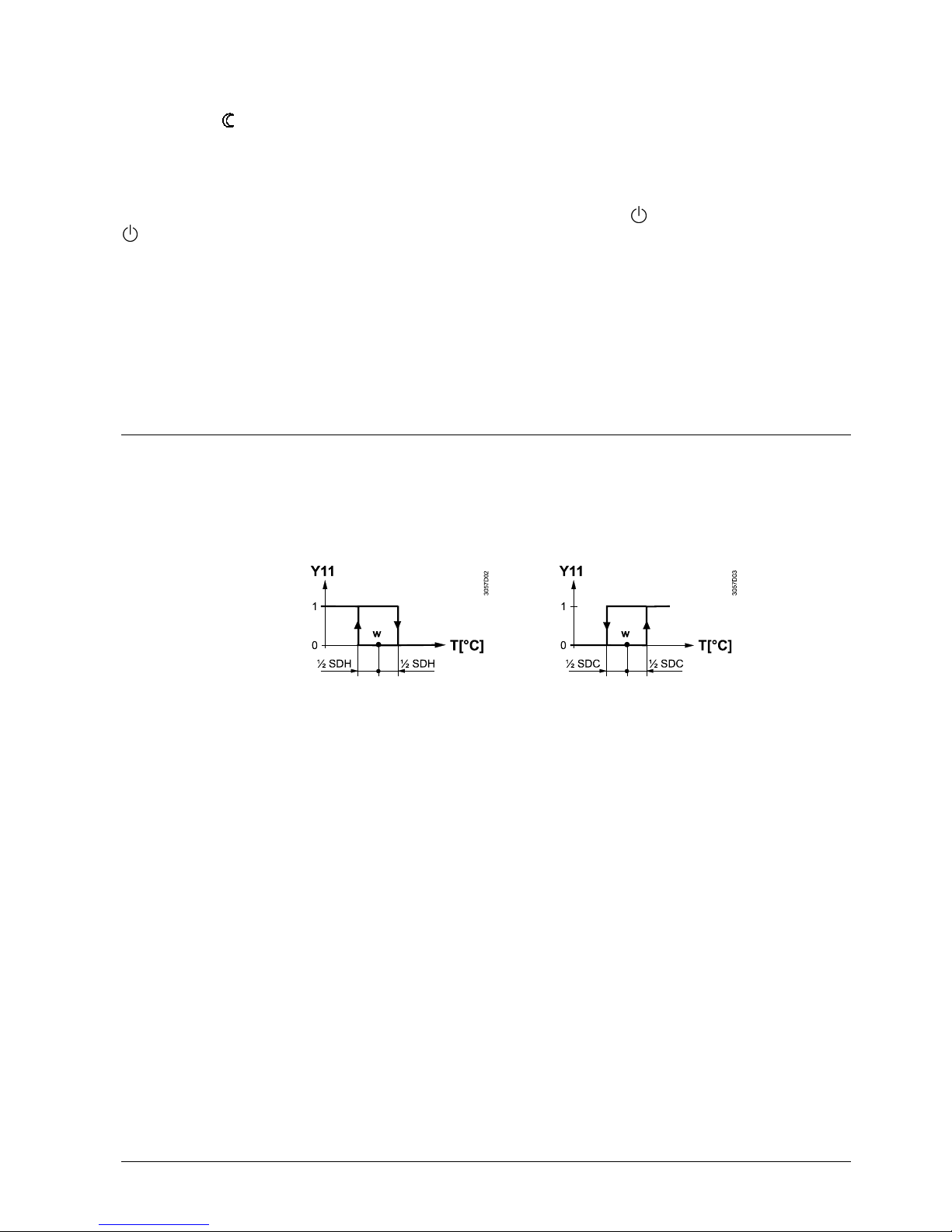
Control sequences
Used in conjunction with a valve, either for heating / cooling with changeover, heating
only or cooling only.
Used in conjunction with a 1-stage compressor for cooling only or heating only.
Heating mode Cooling mode
T[°C] Room temperature
SDH Switching differential “Heating”
W Room temperature setpoint
SDC Switching differential “Cooling”
Y11 Control output “Valve” or “Compressor”
The valve or compressor receives the OPEN command via control output Y11 when
1. the acquired room temperature lies by half the switching differential below the
setpoint (heating mode) or above the setpoint (cooling mode), and
2. control output Y11 was not energized for more than the “Minimum output off time”
(factory setting 1 minute, adjustable via parameter P16)
The valve or compressor receives the CLOSE command via control output Y11 when
1. the acquired room temperature lies by half the switching differential above the
setpoint (heating mode) or below the setpoint (cooling mode), and
2. control output Y11 was energized for more than the “Minimum output on time”;
(factory setting 1 minute, adjustable by parameter P15)
Control output Y12 delivers a control command which is inverted to the control
command at output Y11 and which can be used for normally open valves.
With the RDF110, the changeover between cooling and heating takes place either
automatically via a heating / cooling changeover sensor or a remote changeover
switch. If the controller was set to ”Cooling only” or ”Heating only”, changeover will not
be possible (parameter P22, factory setting ”Cooling only”).
Economy (Energy
saving) mode
(only with RDF110 and
RDF110/IR)
Protection (Standby)
Avoiding damage
due to moisture
(only with RDF110
and RDF110/IR)
Water-based fan coil
application
Compressor-based
application
ON
OFF
Note:
Heating / cooling
mode
Page 4
4/14
Siemens Room Temperature Controllers N3057en
Building Technologies 2014-10-28
With the RDF110.2, when pressing the heating / cooling changeover button , the
controller will change from heating to cooling, or vice versa.
The minimum output on time and off time of Y11 can be adjusted from 1…10 minutes
via parameters P15 and P16. Factory setting is 1 minute. In this case, any readjustment
of the setpoint or of heating / cooling mode changeover will be used immediately for
computing the output status and output Y11 may not hold the minimum on / off time of
1 minute.
If parameter P15 or P16 is set to a level above 1 minute, the minimum on / off time of
Y11 will be maintained as set, even if the setpoint or changeover mode has been
readjusted.
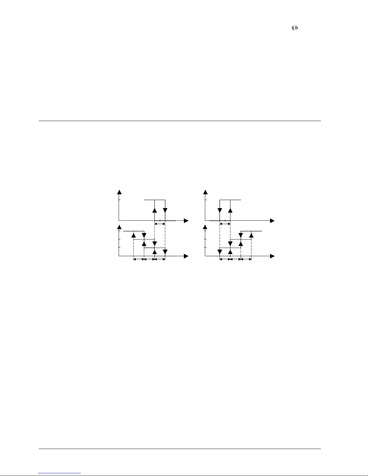
Fan operation
The fan operates either in automatic mode or at the selected speed when using manual
mode. In automatic mode, the fan speed depends on the setpoint and the current room
temperature. When the room temperature reaches the setpoint, the control valve will
close and the fan switch off: Temperature-dependent fan control (see diagram below).
The individual switching differentials of the fan speeds can be adjusted via control
parameters P08 – P13.
Heating mode Cooling mode
W
SDH
SDHSDH2SDH3
Valve
Fan
W
SDC
SDC3
SDC2SDC
Valve
Fan
Y11Y11
Temp
Temp
Temp
Temp
Q3
Q2
Q1
Q3
Q2
Q1
3058D03
If desired, fan control can be set to ”Temperature-independent”, which means that
ventilation is always on, even within the dead zone, using at least fan speed 1. This can
be selected individually for Normal operation using parameter P21 and for Economy
(Energy saving) mode using parameter P20 (also refer to “Avoiding damage due to
moisture”).
In automatic mode, a dwelling time of 2 minutes (factory setting) is active. The fan
maintains that speed for at least 2 minutes before it switches to the next speed. This
dwelling time can be adjusted from 1…5 minutes using parameter P14.
When the fan starts from standstill, it starts with fan speed 3 for 1 second in order to
guarantee a safe fan motor start (to overcome inertia and friction).
Minimum output
on time / off time Y11
Ventilation always on
Dwelling time
Fan start
Page 5
5/14
Siemens Room Temperature Controllers N3057en
Building Technologies 2014-10-28
External sensor input B1-M
With the RDF110, a return air / external room temperature sensor or heating / cooling
changeover sensor can be connected to terminal B1-M. The function of this sensor
input is determined by parameter P22.
Sensor input B1-M is not galvanically separated from the AC 230 V mains supply.
Therefore, only a cable temperature sensor and wiring with sufficient insulation must be
used.
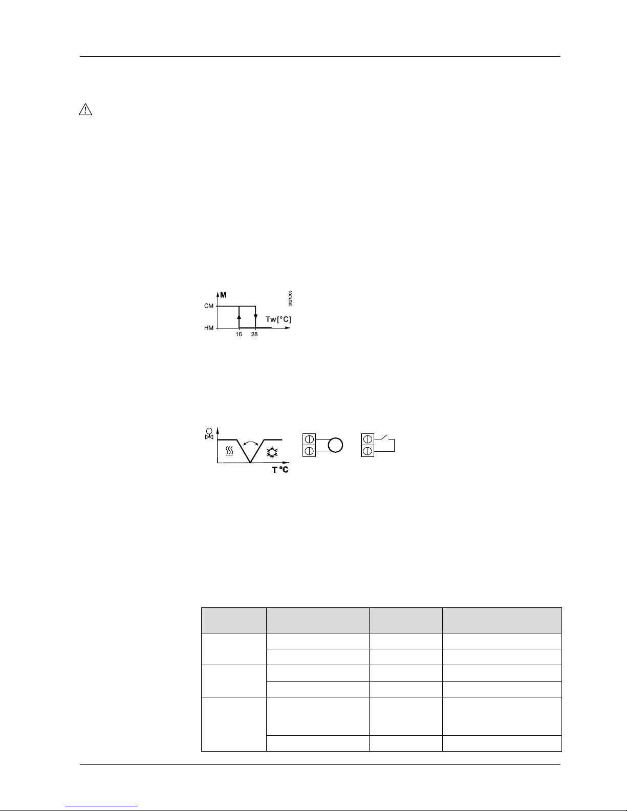
When P22 is set to “Automatic H/C changeover”, the sensor input acts to ensure
automatic heating / cooling changeover. The water temperature acquired by the
changeover sensor (QAH11.1 + ARG86.3) is used to switch from heating to cooling
mode, or vice versa. When the water temperature lies above 28 °C (parameter P24),
the controller switches to heating mode; below 16 °C (parameter P23), it switches to
cooling mode. If, immediately after switching on, the water temperature lies between
the 2 changeover points, the controller will start in heating mode. The water
temperature is acquired at 30-second intervals and the operating state is updated.
Automatic H / C changeover
M
Operating mode
CM
Cooling mode
Tw
Water temperature
HM
Heating mode
The QAH11.1 cable temperature sensor for automatic heating / cooling changeover can
be replaced by an external switch (suited for mains voltage) for manual remote
changeover:
3058Z03
B1
M
T
B1
M
QA H 11 .1
Contact open heating mode
Contact closed cooling mode
With parameter P99 (diagnostic value), automatic heating / cooling changeover can be
checked.
When parameter P22 is set to “Cooling only” or “Heating only”, sensor input
B1-M can be used to connect an external room temperature (QAA32) or a return air
temperature sensor (QAH11.1). Changeover is automatic if a sensor is detected at the
sensor input. With parameter P98 (diagnostic value), the sensor status can be checked.
The following table summarizes the relation between parameter P22, the external
sensor B1-M and variables which the controller uses for maintaining the temperature:
Parameter
P22
Variables:
The controller….
No sensor at
B1-M
QAH11.1/QAA32 at
B1-M
Heating only
is in H/C mode
Heating
Heating
controls according to
Internal sensor
Sensor at B1
Cooling only
is in H/C mode
Cooling
Cooling
controls according to
Internal sensor
Sensor at B1
Automatic
H/C
changeover
is in H/C mode Heating
depending on the
temperature of sensor B1-
M
controls according to
Internal sensor Internal sensor
Automatic heating /
cooling changeover
Remote heating /
cooling changeover
External room or
return air temperature
sensor
Summary
B1-M and P22
Page 6

6/14
Siemens Room Temperature Controllers N3057en
Building Technologies 2014-10-28
External operating mode changeover D1-GND
With the RDF110, a potential-free operating mode changeover switch (window switch,
key card contact, etc.) can be connected to status input D1-GND. No additional power
supply is required for detecting the position of the external switch.
When the switch closes due to an open window, or unoccupied hotel room for instance,
the operating mode will change to Economy (Energy saving). During this external
operating mode changeover, neither the setpoint nor the control parameter nor fan
mode can be changed. When pressing the setpoint or fan mode buttons, ECO will flash
on the display, indicating that the operating mode is overridden from a remote location.
The operating action of the switch (N.C. or N.O.) can be selected via parameter P19.
Error handling
When the room temperature is out of the measuring range, which means above 49 °C
or below 0 °C, the display shows the limiting temperature in flashing figures, e.g. “0 °C”
or “49 °C”.
If the current setpoint is not OFF (see parameters 1 – 4), the controller is in heating
mode and the temperature is below 0 °C, output Y11 will be energized. In all other
cases, Y11 is deenergized. When the temperature returns to the measuring range, the
controller will resume Normal operation.
In case of an external sensor failure (short-circuit or open-circuit), the controller will
immediately switch back to the internal sensor to ensure control.
Should both the external and internal sensor fail, the display will flash “Err” to call the
user‘s attention.
Infrared remote control
The RDF110/IR and RDF110.2/IR have an infrared receiver built in. Together with the
IRA210 infrared remote control, the following operations can be performed from a
remote location:
• Selection of operating mode: Protection (Standby) / Normal operation
• Adjustment of setpoint in Normal operation
• Selection of fan mode: Automatic or manual fan speed
Using parameter P25, infrared remote control can be disabled.
Temperature out
of range
External sensor
failure
Page 7

7/14
Siemens Room Temperature Controllers N3057en
Building Technologies 2014-10-28
Control parameters
With the RDF110 and RDF110.2, a number of control parameters can be readjusted to
optimize the control performance. These parameters can also be set during operation
without opening the unit. In the event of a power failure, all control parameter settings
will be maintained.
The parameters can be changed as follows:
1. Set the controller to Protection (Standby)
.
2. Press buttons
and simultaneously for 3 seconds. Release them and,
within 2 seconds, press button
again for 3 seconds. Then, the display will
show “P01“.
3. Select the required parameter by repeatedly pressing buttons
and :
P01 P02 P22 P98
+- +
- -
+
3057z03
P99
-
+
P25
+-
4. By pressing buttons
and simultaneously, the current value of the selected
parameter appears, which can be changed by repeatedly pressing buttons
or
.
5. By pressing buttons
and simultaneously again or 5 seconds after the last
press of a button, the last parameter will be displayed again.
6. If you wish to display and change additional parameters, repeat steps 3
through 5.
7. 10 seconds after the last display or setting, all changes will be stored and the
controller returns to Protection (Standby).
Parameters not used by the RDF110.2 are not available and cannot be displayed.
The factory setting of the control parameters can be reloaded as follows:
1. Set the controller to Protection (Standby)
.
2. Press buttons
and simultaneously for 3 seconds. Release them and,
within 2 seconds, press operating mode selector button
2 times.
Then, the display will show “888“ during the reloading process.
Parameter settings
Note:
Parameter reset
Page 8

8/14
Siemens Room Temperature Controllers N3057en
Building Technologies 2014-10-28
Para-
meter
Meaning Setting range Factory
setting
P01
Setpoint of heating in Economy (Energy saving) mode
(Wheat
Eco
)
OFF, 5 °C…Wcool
Eco
16 °C
1)
P02
Setpoint of cooling in Economy (Energy saving) mode
(Wcool
Eco
)
OFF, Wheat
Eco
…40 °C
28 °C1)
P03
Setpoint of heating in Protection (Standby) (Wheat
Stb
)
OFF, 5 °C…Wcool
Stb
OFF
P04
Setpoint of cooling in Protection (Standby) (Wcool
Stb
)
OFF, Wheat
Stb
…40 °C
OFF
P05
Minimum setpoint limitation in Normal operation (Wmin
Comf
)
5 °C…Wmax
Comf
5 °C
P06
Maximum setpoint limitation in Normal operation (Wmax
Comf
)
Wmin
Comf
…40 °C
35 °C
P07
Sensor calibration
-3…+3 K
0 K
P08
Switching differential heating mode SDH
0.5…+4K
2 K
P09
Switching differential cooling mode SDC
0.5…+4K
1 K
P10
Switching differential fan speed 2 in heating mode SDH2
0.5…+4K
1 K
P11
Switching differential fan speed 2 in cooling mode SDC2
0.5…+4K
1 K
P12
Switching differential fan speed 3 in heating mode SDH3
0.5…+4K
1 K
P13
Switching differential fan speed 3 in cooling mode SDC3
0.5…+4K
1 K
P14
Dwelling time of auto fan speeds
1…5 minutes
2 min
P15
Minimum output on time (Y11)
1…10 minutes
1 min
P16
Minimum output off time (Y11)
1…10 minutes
1 min
P17
Selection of °C or °F
°C or °F
°C
P18
Display of temperature or setpoint
OFF: Setpoint
ON: Room (or return air)
temperature
ON
P19 Operating action of remote changeover input
0: Normally open (N.O)
1: Normally closed (N.C.)
01)
P20
Fan control in
Economy (Energy saving) mode
OFF in dead zone
ON in dead zone
OFF1)
P21 Fan control in Normal operation
OFF in dead zone
ON in dead zone
OFF
P22 Heating / cooling mode
0: Heating only
1: Cooling only
2: Automatic H/C
changeover
1: Cooling
only
1)
P23
Heating / cooling changeover switching point cooling
10…25 °C
16 °C1)
P24
Heating / cooling changeover switching point heating
27…40 °C
28 °C1)
P25 Infrared receiver (only with RDF.../IR)
0: Disabled
1: Enabled
1
P98 Active temperature sensor
0: Internal sensor
1: External sensor
Diagnostic
value1)
P99
Value of current heating / cooling changeover temperature
reading and indication of current mode
100 = input open mode
0…49 °C = cur. temp. value
00 = input bridged
mode
OFF= not commissioned as
automatic H/C changeover
Diagnostic
value
1)
1) Not available with RDF110.2
Type summary
Type
Features
RDF110
With input for automatic heating / cooling changeover or return air
temperature sensor
With input for operating mode changeover
RDF110.2
With manual heating / cooling changeover
Without input for sensor
Without input for operating mode changeover
RDF110/IR *)
Same as RDF110 plus infrared remote control
RDF110.2/IR *)
Same as RDF110.2 plus infrared remote control
*) Type is not orderable any more
Control parameters of the RDF110 and RDF110.2
Page 9

9/14
Siemens Room Temperature Controllers N3057en
Building Technologies 2014-10-28
Equipment combinations
Type of unit
Type
Data Sheet*)
Infrared remote control
IRA210
-
Cable temperature sensor
QAH11.1
1840
Room sensor
QAA32
1747
Changeover mounting kit
ARG86.3
1840
Electromotoric on / off valve and actuator
MVI…/MXI…
4867
Electromotoric on / off actuator
SFA21...
4863
Thermal actuator (for radiator valve)
STA21...
4893
Thermal actuator (for small valves 2.5 mm)
STP21...
4878
Zone valve actuators
(only available in AP, UAE, SA and IN)
SUA…
4830
*) The documents can be downloaded from http://siemens.com/bt/download.
Accessories
Description
Type
Adapter plate 120 x 120 mm for 4“ x 4“ conduit boxes
ARG70
Adapter plate 96 x 120 mm for 2“ x 4“ conduit boxes
ARG70.1
Adapter plate for surface wiring 112 x 130 mm
ARG70.2
Ordering
When ordering, please prodive name and type:
E.g. room temperature controller RDF110
The IRA210 infrared remote control is to be ordered as a separate item
The QAH11.1 can be used as a return air temperature or automatic heating / cooling
changeover sensor. In case it is used as a changeover sensor, the ARG86.3
changeover sensor mounting kit is to be ordered as a separate item.
Valve actuators are to be ordered as separate items.
Mechanical design
The controller consists of two parts:
• Plastic housing which accommodates the electronics, the operating elements and the
built-in room temperature sensor
• Mounting base
The housing engages in the mounting base and snaps on.
The base carries the screw terminals.
Setting and operating
elements
Page 10

10/14
Siemens Room Temperature Controllers N3057en
Building Technologies 2014-10-28
1 Display of the room temperature, setpoints and control parameters
2
Symbol used when displaying the current room temperature
3 Operating mode
Normal operation
Economy (Energy saving) mode
4 Protection (Standby) / fan mode status
Protection (Standby) mode
AUTO Auto fan active
fan speed low, medium, high
5
in cooling mode
in heating mode
6 Buttons for adjusting the setpoints and the control parameters
7 Button for changing fan operation and Protection (Standby) (
)
8 Manual heating / cooling changeover (
) (only with RDF110.2)
9 Infrared receiver (only with RDF110…/IR)
Mounting and installation
The room controller can be mounted on a wall or inside the fan coil unit. The mounting
location on a wall should not be in niches or bookshelves, not behind curtains, above or
near heat sources and not exposed to direct solar radiation. Mounting height is about
1.5 m above the floor.
The controller can be fitted on a recessed conduit box.
When using a heating / cooling changeover sensor, then, before fitting the sensor,
thermal conductive paste must be applied to the location on the pipe where the sensor
is placed.
Also refer to the Mounting Instructions B3057 enclosed with the controller.
• Wiring, protection and earthing must be installed in compliance with local
regulations. It must be made certain that safety extra low-voltage lines (SELV
circuit) are clearly separated from AC 230 V mains voltage cable
• The cables to the controller, external sensor, fan and valves carry AC 230 V mains
voltage and must be appropriate sized
• Only sensors and valves rated for AC 230 V may be used
• The AC 230 V mains supply line must have a circuit breaker with a rated current of
no more than C 10 A
Warning!
No internal line protection for supply lines to external consumers
(Q1, Q2, Q3, Y11, Y12)
Risk of fire and injury due to short-circuits!
• Adapt the line diameters as per local regulations to the rated value of the installed
overcurrent protection device.
• Maximum 10 changeover contact inputs B1-M can be connected in parallel if an
external switch is used in place of a changeover sensor. The switch must be suited
for AC 230 V. The cable length must not exceed 80 m overall
• Maximum 10 operating mode changeover contact inputs D1-GND can be connected
in parallel. The cable length must not exceed 80 m overall
Legend
Wiring
Page 11

11/14
Siemens Room Temperature Controllers N3057en
Building Technologies 2014-10-28
After applying power, the controller makes a reset during which all LCD segments flash,
indicating that the reset has been correctly made. This takes about 3 seconds. Then,
the controller is ready for commissioning by qualified HVAC staff. The control
parameters of the controller can be set to ensure optimum performance of the whole
system (also refer to “Setting the control parameters”).
• Only with RDF110: Depending on the application, the heating / cooling mode needs
to be set via parameter P22. Factory setting is “Cooling only”. When using the
”Automatic heating / cooling changeover” function, P22 must be set to “Automatic
H/C changeover”.
Note: When P22 is set to “Automatic H/C changeover”, the built-in sensor is used
for acquiring the room temperature
• If the controller is used in conjunction with a compressor, the minimum output on
time (parameter P15) and off time (parameter P16) of Y11 must be adjusted in order
not to harm the life time of the compressor
• If the room temperature displayed by the controller does not accord with the room
temperature effectively measured, the temperature sensor can be recalibrated. In
that case, parameter P07 must be changed
• For comfort and energy saving reasons, it is suggested to review the setpoints and
setpoint ranges (parameters P01…P06) and, if necessary, to change them
accordingly
• Only with RDF110: Parameters P98 and P99 are diagnostic values and help check
the system. With P98, the status of the active temperature sensor is shown and,
with P99, the status of the heating / cooling changeover sensor
Disposal
The devices are considered electronics devices for disposal in term of European
Directive 2012/19/EU and may not be disposed of as domestic waste.
• Dispose of the device via the channels provided for this purpose
• Comply with all local and currently applicable laws and regulations.
Technical data
Operating voltage
AC 230 V +10/-15 %
Frequency
50/60 Hz
Power consumption
max. 8 VA
No internal fuse
External preliminary protection with max. C 1
0 A circuit breaker in the supply line
required under all circumstances
Fan control Q1, Q2, Q3- N
Rating
AC 230 V
5 mA…4(2)A
Control output Y11
-N (N.O.) / Y12-N (N.C.)
Rating
AC 230 V
5 mA…4(2)A
Changeover or external room temperature sensor B1-M
Temperature sensor
Voltage against earth
Cable length
QAH11.1, safety class II
AC 230 V
max. 80 m (min. 1.5 mm2)
Status input D1 and GND
Contact sensing
Insulation against mains
Operating action
Cable length
SEL
V DC 6…15 V / 3…6 mA
4 kV, reinforced insul
ation
selectable (N.O. / N.C.)
max. 80 m (min. 1.5 mm2)
Infrared receiver (only with RDF110…/IR)
Transmission distance
Orientation angle
≤
7.5 m
≤ ± 30 °
Commissioning
Heating / cooling mode
Compressor
-based
application
Calibrating the sensor
Setpoint and range
limitation
Diagnostic values
Power supply
Outputs
Inputs
Page 12

12/14
Siemens Room Temperature Controllers N3057en
Building Technologies 2014-10-28
Switching differential, adjustable from 0.5..4 K
Heating mode (factory setting)
Cooling mode (factory setting)
2
K
1 K
Setpoint setting range
Normal operation
Economy (Energy saving) (only with RDF110)
Protection (Standby)
5...40 °C
OFF, 5...40 °C
OFF, 5...40 °C
Factory setting of setpoints
Normal operation
Economy (Energy saving) in heating / cooling
mode
Protection (Standby) (heating and cooling mode)
20 °C
16 °C / 28 °C
OFF
Built-in room temperature sensor
Measuring range
Accuracy at 25 °C
Temperature calibration range
0…49 °C
<
± 0.5 K
± 3.0 K
Resolution of settings and displa
y
Setpoints
Current temperature value displayed
0.5 °C
0.5 °C
Operation
Climatic conditions
Temperature
Humidity
to IEC 60721-3-3
class 3K5
0
...+50 °C
<95 % r.h.
Transport
Climatic conditions
Temperature
Humidity
Mechanical conditions
to IEC
60721-3-2
class 2K3
−
25...+60 °C
<
95 % r.h.
class 2M2
Storage
Climatic conditions
Temperature
Humidity
to IEC 60721-3-1
class 1K3
−
25...+60 °C
<95 % r.h.
EU Conformity (CE)
CE1T3057xx
*)
RCM Conformity
CE1T3057en_C1
*)
Devices of safety class
II to EN 60730-1
Pollution class
normal
Degree of protection of housing
IP 30 to EN 60 529
Connection terminals
solid wires or prepared
stranded wires
2 x 0.4
-1.5 mm2 or 1 x 2.5
mm2
Weight
0.28 kg
Color of housing front
white, NCS S 0502-G
(RAL 9003)
*) The documents can be downloaded from http://siemens.com/bt/download.
Operational data
Enviro
nmental
conditions
Norms and standards
General
Page 13

13/14
Siemens Room Temperature Controllers N3057en
Building Technologies 2014-10-28
Connection terminals
L B1* M D1 GND
*
N Q1 Q2 Q3 Y11 N
3057G01
Y12
SELV
AC 230 V
L, N Operating voltage AC 230 V
B1* Changeover (QAH11.1+ ARG86.3) or
external room temperature sensor (QAH11.1 /
QAA32)
M Measuring neutral for sensor
D1, GND* Status input for potential-free operating
mode changeover switch
Q1 Control output “Fan speed 1 AC 230 V
Q2 Control output “Fan speed 2 AC 230 V
Q3 Control output “Fan speed 3 AC 230 V
Y11 Control output “Valve” AC 230 V (N.O.,
for normally closed valves) or output for
compressor
Y12 Control output “Valve” AC 230 V (N.C.,
for normally open valves)
* Only with RDF110 or RDF110/IR
Connection diagrams
Application:
2-pipe fan coil units
3
0
5
7
A
0
1
B1* Return air temperature sensor (QAH11.1)
or external room temperature sensor (QAA32)
B2* Changeover sensor (temperature sensor
QAH11.1 + changeover mounting kit
ARG86.3)
M1 3-speed fan
N1 Room temperature controller RDF110...
S1* External operating mode changeover switch
V1 Zone valve
* Only with RDF110 or RDF110/IR
Application:
Compressor
in DX type equipment
3
0
5
7
A
0
2
B1* Return air temperature sensor (QAH11.1)
or external room temperature sensor (QAA32)
B2* Changeover sensor (temperature sensor
QAH11.1 + changeover mounting kit
ARG86.3)
M1 3-speed fan
N1 Room temperature controller RDF110..
S1* External operating mode changeover switch
C1 Compressor
* Only with RDF110 or RDF110/IR
Note: For compressor application, RDF110 or
RDF110/IR is recommended
Page 14

14/14
Siemens Room Temperature Controllers N3057en
Building Technologies 2014-10-28
Dimensions
102
120.3
128
30
3057M02
28
28
35
30
10.15
94.85
28.7
30
4
2.5
21.85
34.15
120.3
31.65
24.35
11.8
2828
4
3057M03
Controller
Mounting base
2006 (– 2014) Siemens Switzerland Ltd. Subject to change
 Loading...