

Page 1
1
Answers for infrastructure.
RDG/RDF –
room thermostats
Application guide
Page 2
Fan coil unit
4-pipe with
el. heater
Chilled/
heated ceiling
Chilled/heated
ceiling with
el. heater
Chilled/heated
ceiling and
radiator
Chilled
ceiling
and radiator
Compressor
for heating
or cooling
Compressor
with el. heater
Compressor
for heating
and cooling
2-stage
compressor
for heating
or cooling
2-pipe
el. heater or
radiator
2-pipe
Single duct
Single duct
with el. heater
Single
duct with
heat/cool coil
Single duct
and radiator
2-stage
heating
or cooling
Variable Air Volume
(VAV)
Heat pumps
Universal
Application overview
Page 3

3
Contents
Introduction …………………………………………...................................................................4
Before you start.........................................................................................................4
Description of RDG range…………………………………......................................................4
Products range RDG ……………………………...................................................................5
Description of RDF semi flush-mount range………………………………..............................5
Products range RDF………………………………………………….............................................5
Description of applications…………………………............................................................6
The RDG/RDF offers extensive features and functions..................................................6
Fan coil – application overview…………………................................................................8
Fan coil – product overview……………………….............................................................. 10
Universal – application overview………………….………………….………………….…………...12
Universal – product overview………………….………………….………………….…………........14
Heat pumps – application overview……………….........................................................15
Heat pumps – product overview…………………….........................................................16
VAV – application overview…………………………..........................................................18
VAV – product overview………………………………..........................................................19
How to prepare and set up your room thermostats....................................................20
Introduction............................................................................................................20
Control parameters..................................................................................................20
Installation and set up………………………………………………………………….....................20
Application-specific parameter.................................................................................21
Communicating, KNX- compatible thermostats..........................................................22
Suggestions for energy saving……………………………………………………….....................22
FAQ.........................................................................................................................22
Reference to the basic documentation……………………………………………..................... 23
Application examples………………………………………………………………….......................24
Overview – fan coil room thermostats………………......................................................28
Overview – universal room thermostats……………......................................................30
Page 4

4
Introduction
The new thermostat range RDG and RDF is very versatile and consists of numerous
products. The RDG and RDF offer many new features and cover a broad field of
applications.
This document shall:
– give you an overview of the new ranges RDG and RDF
– assist you by the selection of the suitable product, and
– provide you with helpful information for installation and commissioning
The section “application overview” for each main application – i.e. fan coil unit,
universal, heat pumps and VAV – shows what applications are covered by which
thermostat line.
The section “product overview” shows the available thermostat variants and their
supported applications.
Before you start
Before you start selecting a thermostat, we recommend to make the following
preselection:
– Type of main application: fan coil unit, universal, heat pump or VAV
– Application: e.g. 2-pipe with electrical heater
– Type of control output 1: ON/OFF, PWM, 3-position, or DC 0...10 V
– Type of control output 2: ON/OFF, PWM, 3-position, or DC 0…10 V
– Type of inputs: e.g. external room temperature sensor, changeover sensor,
key card switch etc.
– Type of thermostat: standalone, standalone with 7-day timer, or communicating
thermostat
– Thermostat design: wall- or semi flush-mounted
– Other important requirements
Description of RDG range
The RDG represents a compact wall-mounted version and is of elegant and modern design.
This range consists of 2 lines of versatile products – RDG100 line and RDG400 line:
– RDG100 line for fan coil units plus universal (e.g. chilled ceilings or radiators)
and heat pump applications
– RDG400 line for VAV applications
The thermostats are available as standalone versions, standalone with 7-day time program,
and KNX versions tailored for use with Synco 700 via LTE-mode, for integration in Synco
living or BACS (building automation and control system) via S-mode.
Page 5

5
Products range RDG
– RDG100 – the versatile standalone thermostat with ON/OFF and modulating
(PWM or 3-position) outputs
– RDG100T – the versatile standalone thermostat with 7-day time program and same
functionality as RDG100 plus infrared receiver for remote control
– RDG100KN – the versatile communicating thermostat with the same functionality as
RDG100 including KNX interface
– RDG110 – the robust standalone thermostat with relay outputs (SPDT) for applications
with max. 5 A current on the control outputs. This thermostat is the ideal solution for
ON/OFF applications with electrical heater, heat pumps and heat pumps with reversing
valve (RV).
– RDG140 – the modulating thermostat operating on AC 24 V (SELV) with DC 0…10 V
control outputs.
– RDG160 – the energy efficient modulating thermostat for controlling of electronic
commutated fan motors (ECM Fan), operating on AC 24 V (SELV) with DC 0...10 V
outputs for valve and fan
– RDG400 – the versatile standalone thermostat for VAV applications with modulating
and ON/OFF outputs
– RDG400KN – the versatile communicating thermostat with the same functionality as
RDG400, including KNX interface.
On each thermostat, a number of control parameters can be readjusted to optimize the
control performance.
Description of RDF semi flush-mount range
The range represents a compact semi-flush mount solution designed to fit into conduit
boxes with fixing center 60.3 mm (BSI standard BS4662).
The RDF and RDU are 2 lines of versatile and slim products:
– RDF line for fan coil unit and heat pump applications
– RDU line for VAV applications
The thermostats are available as standalone, standalone with 7-day time program and KNX
versions tailored for use with Synco 700 via LTE-mode, for Synco living or for integration in
BACS via S-mode.
Products range RDF
– RDF300 – the versatile standalone thermostat with ON/OFF or modulating 3-position
outputs
– RDF300.02 – offers in addition backlit digital display
– RDF400.01 – the versatile standalone thermostat with 7-day time program and
same functionality as RDF300, plus infrared receiver for remote control and backlit
digital display
– RDF301 – communicating thermostat with the same functionality as RDF300,
including KNX interface and backlit digital display
– RDF301.50 – communicating thermostat with the same functionality as RDF301,
plus switching groups for lighting and blind control via KNX S-mode
– RDF340 – modulating thermostat operating on AC 24 V (SELV) with DC 0…10 V
control outputs
– RDF310.2 – basic standalone thermostat for 2-pipe applications.
– RDF310.21– offers in addition backlit digital display and infrared receiver for
remote control
– RDF410.21 – basic standalone thermostat for 2-pipe applications with 7-day time
program, backlit digital display and infrared receiver for remote control
– RDU340 – the versatile standalone thermostat for VAV applications with modulating
DC 0…10 V and ON/OFF outputs
– RDU341 – communicating thermostat with the same functionality as RDU340,
including KNX interface
Page 6
6
Description of applications
The RDG/RDF thermostats cover the following applications:
Fan coil units via ON/OFF or modulating control outputs:
– 2-pipe system
– 2-pipe system with electrical heater
– 2-pipe system and radiator/floor heating
1
– 4-pipe system
– 4-pipe system with electrical heater
1
– 2-stage heating or cooling system
1
VAV systems via ON/OFF or modulating control outputs:
– Single-duct system
– Single-duct system with electrical heater
– Single-duct system and radiator/floor heating
1
– Single-duct system with heating/cooling coil
1
Chilled/heated ceilings (or radiators) via ON/OFF or modulating control outputs:
– Chilled/heated ceiling
– Chilled/heated ceiling with electrical heater
– Chilled/heated ceiling and radiator/floor heating
1
– Chilled/heated ceiling, 2-stage heating or cooling
1
Page 7

7
Heat pumps with DX type equipment:
– 1-stage compressor for heating or cooling
– 1-stage compressor for heating or cooling with electrical heater
– 1-stage compressor for heating or cooling and radiator/floor heating
– 1-stage compressor for heating and cooling with reversing valve
– 2-stage compressor for heating or cooling
1
The RDG/RDF offers extensive features and functions
2
– Operating mode: Comfort, Energy-saving and Protection
– Energy-saving functions: external operating mode switchover, 7-day time program,
keycard or window contact, minimum and maximum setpoint limitation, etc.
– Numerous application selectable via DIP switch
– Heating/cooling changeover: automatic or manual
– Control output signals: ON/OFF (triac or relay), PWM, 3-position and DC 0...10 V
– Fan control: automatic or manual fan speed for 1-speed, 3-speed or ECM
3
) fan
– Fan operation: fan enable, heating only, cooling only, fan disable
– Multifunctional inputs: (function selectable)
– Remote temperature sensor
– Heating/cooling changeover sensor or switch
– Operating mode switchover for keycard, window or time switch contact
– Electrical heater release
– Dew point sensor
– Fault input
– 7-day time program
– Timer for prolong presence and absence function
– Keypad lock function
– Backlit digital display
– Infrared remote control
– Reminder for cleaning fan filter
– Floor temperature limitation function
– Various parameters for setpoint adjustment and control setting
– KNX communication interface: Synco700 via LTE mode,
Synco living and BACS (building automation and control system) via S-mode
– Switching groups for lighting and blind control via KNX S-mode
1
Applications covered only with RDG thermostats
2
Feature availability depends on thermostat type
3
Electronic commutated motor, DC 0...10 V
Page 8
Application Type of control outputs
RDG…
Wall-mounted range
RDF…
Semi flush-mounted range
Two-pipe system
2-pipe (ON/OFF) RDG100... RDG110 RDF300... RDF310...
RDF400... RDF410...
2-pipe mod. (PWM) RDG100...
2-pipe mod. (3-pos.) RDG100... RDF300... RDF400...
2-pipe mod. (DC 0...10 V) RDG140 RDF340
2-pipe mod. (DC 0...10 V) ECM fan control (DC 0...10 V) RDG160
Two-pipe system with el. heater
2-pipe (ON/OFF), with el. heater (ON/OFF) RDG100... RDG110 RDF300... RDF400...
2-pipe (ON/OFF), with el. heater (mod. PWM or 3-pos.) RDG100...
2-pipe mod. (PWM), with el. heater (ON/OFF, PWM or 3-pos.) RDG100...
2-pipe mod. (3-pos.), with el. heater (ON/OFF, PWM or 3-pos.)
RDG100...
2-pipe mod. (DC 0...10 V), with el. heater (DC 0...10 V) RDG140 RDF340
2-pipe mod. (DC 0...10 V), with el. heater (DC 0...10 V).
ECM fan control (DC 0...10 V)
RDG160
8
Fan coil – application overview
Application description
– Control sequences for heating and/or cooling,
1 or 2 stages
– Multifunctional inputs for keycard contact,
external sensor, etc.
– Automatic or manual heating/cooling changeover
– Automatic or manual fan speed
– 3-speed, 1-speed and mod. (ECM) fan control
(DC 0...10 V)
– Fan operation selectable in heating and cooling
(enable, disable, only heating or only cooling)
Page 9
9
Application Type of control outputs
RDG…
Wall-mounted range
RDF…
Semi flush-mounted range
Two-pipe system and radiator heating
2-pipe (ON/OFF) and radiator (ON/OFF) RDG100... RDG110
2-pipe (ON/OFF) and radiator (mod. PWM or 3-pos.) RDG100...
2-pipe mod. (PWM) and radiator (ON/OFF, PWM or 3-pos.) RDG100...
2-pipe mod. (3-pos.) and radiator (ON/OFF, PWM or 3-pos.) RDG100...
2-pipe mod. (DC 0...10 V) and radiator (DC 0...10 V) RDG140
2-pipe mod. (DC 0...10 V) and radiatior (DC 0...10 V).
ECM fan control (DC 0...10 V)
RDG160
Four-pipe system
4-pipe (ON/OFF) RDG100... RDG110 RDF300... RDF400...
4-pipe mod. (PWM) RDG100...
4-pipe mod. (3-pos.) RDG100...
4-pipe mod. (DC 0...10 V) RDG140 RDF340
4-pipe mod. (DC 0...10 V). ECM fan control (DC 0...10 V) RDG160
Four-pipe system with el. heater
4-pipe (ON/OFF) with el. heater (ON/OFF) RDG100…
4-pipe (ON/OFF and 3-pos.) with el. heater (ON/OFF) RDG100…
4-pipe mod. (PWM) with el. heater (ON/OFF) RDG100…
4-pipe mod. (PWM and 3-pos). with el. heater (ON/OFF) RDG100…
Two-stage, cooling or heating
2-stage (ON/OFF) heating or cooling RDG100... RDG110
2-stage mod. (PWM) heating or cooling RDG100...
2-stage mod. (3-pos.) RDG100...
2-stage mod. (DC 0...10 V) RDG140
2-stage mod. (DC 0...10 V). ECM fan control (DC 0...10 V)
RDG160
Abbreviation
ON/OFF: 2-position control
3-pos.: Modulating 3-position control signal
PWM: Pulse Width Modulation control signal
DC 0...10 V: Modulating DC 0...10 V control signal
ECM fan: Electronic Commutated Motor for fan, DC 0...10 V
el. heater: Electrical heater
mod. output: Modulating output
Page 10
10
Product Application Standalone
Standalone
with
7-day time
program
Communicating
KNX
Wall-mounted units: RDG
RDG100…
Versatile thermostats with
control output signal (ON/OFF)
or mod. (PWM or 3-pos.).
– 2-pipe (ON/OFF, PWM or 3-pos)
– 2-pipe with electrical heater
– FCU: (ON/OFF, PWM or 3-pos)
– el. heater: (ON/OFF, PWM or 3-pos.)
– 2-pipe and radiator
– FCU: (ON/OFF, PWM or 3-pos)
– radiator: (ON/OFF, PWM or 3-pos.)
– 4-pipe (ON/OFF, PWM and/or 3-pos)
– 4-pipe with electrical heater
– FCU: (ON/OFF, PWM and ON/OFF, PWM or 3-pos)
– el. heater: (ON/OFF)
– 2-stage heating or cooling
– FCU: (ON/OFF, PWM or 3-pos)
RDG100 RDG100T RDG100KN
RDG110
Robust thermostat with
relay outputs (SPDT) for
ON/OFF – control sequences
– 2-pipe (ON/OFF)
– 2-pipe (ON/OFF) with el. heater (ON/OFF)
– 2-pipe (ON/OFF) and radiator (ON/OFF)
– 4-pipe (ON/OFF)
– 2-stage (ON/OFF) heating or cooling
RDG110
RDG140
Thermostat for mod. control
sequences with (DC 0...10 V)
output signals
– 2-pipe (DC 0...10 V)
– 2-pipe (DC 0...10 V) with el. heater (DC 0...10 V)
– 2-pipe (DC 0...10 V) and radiator (DC 0...10 V)
– 4-pipe heating (DC 0...10 V) and cooling (DC 0...10 V)
– 2-stage (DC 0...10 V) heating or cooling
RDG140
RDG160
Thermostat for mod. control
sequences with (DC 0...10 V)
output signals for valves and
fan control (ECM) DC 0...10 V
– 2-pipe (DC 0...10 V)
– 2-pipe (DC 0...10 V) with el. heater (DC 0...10 V)
– 2-pipe (DC 0...10 V) and radiator (DC 0...10 V)
– 4-pipe heating (DC 0...10 V) and cooling (DC 0…10 V)
– 2-stage (DC 0...10 V) heating or cooling
RDG160
Semi flush-mounted units: RDF
RDF300../400…*
Versatile thermostats with
relay ouputs: ON/OFF or 3-pos.
– 2-pipe
– FCU: (ON/OFF or 3-pos)
– 2-pipe (ON/OFF) with el. heater (ON/OFF)
– 4-pipe (ON/OFF)
RDF300... RDF400... RDF301...
RDF310…/410..*
Basic thermostats for 2-pipe
application
– 2-pipe (ON/OFF)
RDF310… RDF410.21
RDF340
Thermostat for mod. control
sequences with (DC 0...10 V)
output signals
– 2-pipe (DC 0...10 V)
– 2-pipe (DC 0...10 V) with el. heater (DC 0...10 V)
– 4-pipe heating (DC 0...10 V) and cooling (DC 0...10 V)
RDF340
*Variants
RDF300 Basic version
RDF300.02 Unit with backlight
RDF300.02/SL Unit with backlight, silver
RDF400.01 Basic version
RDF400.01/SL Unit with backlight, silver
RDF301 Communicating unit
RDF301.50 Communicating unit with 4 buttons for light and shutter
RDF310.2 Basic version
RDF310.21 Basic version with backlight and infrared remote control
RDF410.21 Basic version with backlight, 7-day time program and infrared remote control
Fan coil – product overview
Page 11

11
Notes
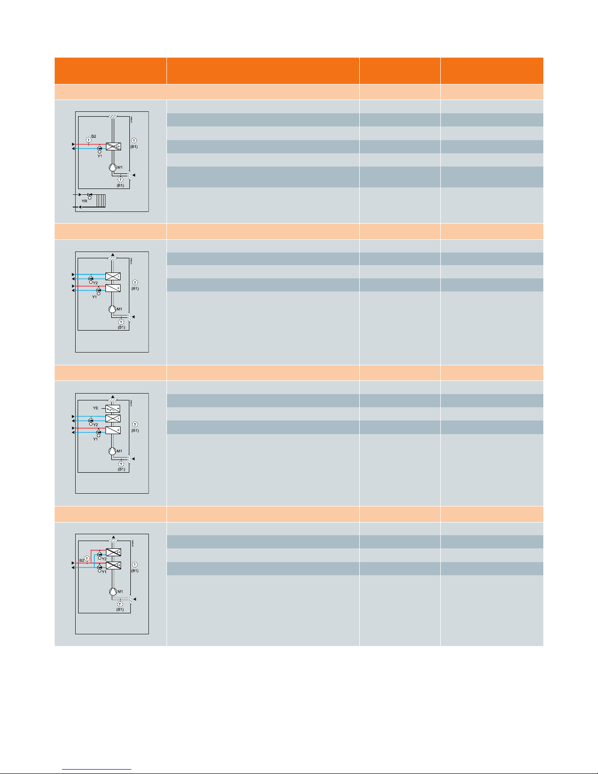
Page 12

Application
Type of control outputs
RDG…
Wall-mounted range
Chilled/heated ceiling with changeover
Chilled/heated ceiling (ON/OFF) RDG100... RDG110
Chilled/heated ceiling mod. (PWM) RDG100...
Chilled/heated ceiling mod. (3-pos.) RDG100...
Chilled/heated ceiling mod. (DC 0...10 V) RDG140
12
Universal – application overview
Chilled/heated ceiling or radiator
Chilled/heated ceiling and el. heater
Chilled/heated ceiling (ON/OFF) and el. heater (ON/OFF) RDG100... RDG110
Chilled/heated ceiling (ON/OFF) and el. heater (mod. PWM or 3-pos.) RDG100...
Chilled/heated ceiling mod. (PWM) and el. heater (ON/OFF, PWM or 3-pos.) RDG100...
Chilled/heated ceiling mod. (3-pos.) and el. heater (ON/OFF, PWM or 3-pos.)
RDG100...
Chilled/heated ceiling mod. (DC 0...10 V) and el. heater (DC 0...10 V) RDG140
Application description
– For heating and/or cooling applications with heated/chilled
ceiling or radiator
– Control sequences for heating and/or cooling, 1- or 2-stages
– Dew point monitoring
–
Multifunctional inputs for keycard contact, external sensor, etc.
– Automatic or manual heating/cooling changeover
– Fan operation selectable in heating and cooling
(enable, disable, only heating or only cooling)
Page 13

13
Application Type of control outputs
RDG…
Wall-mounted range
Chilled/heated ceiling and radiator
Chilled/heated ceiling (ON/OFF) and radiator (ON/OFF) RDG100... RDG110
Chilled/heated ceiling (ON/OFF) and radiator (mod. PWM or 3-pos.) RDG100...
Chilled/heated ceiling mod. (PWM) and radiator (ON/OFF, PWM or 3-pos.) RDG100...
Chilled/heated ceiling mod. (3-pos.) and radiator (ON/OFF, PWM or 3-pos.) RDG100...
Chilled/heated ceiling mod. (DC 0...10 V) and radiator (DC 0...10 V) RDG140
Chilled ceiling and radiator
Chilled ceiling (ON/OFF) and radiator (ON/OFF) RDG100... RDG110
Chilled ceiling (ON/OFF) and radiator (mod. PWM or 3-pos.) RDG100...
Chilled ceiling (PWM) and radiator (ON/OFF, PWM or 3-pos.) RDG100...
Chilled ceiling (3-pos.) and radiator (ON/OFF, PWM or 3-pos.) RDG100...
Chilled ceiling (DC 0...10 V) and radiator (DC 0...10 V) RDG140
Chilled/heated ceiling 2 stage cooling or 2-stage heating
2-stage (ON/OFF) heating or cooling RDG100... RDG110
2-stage mod. (PWM) heating or cooling RDG100…
2-stage mod. (3-pos.) heating or cooling RDG100…
2-stage mod. (DC 0...10 V) heating or cooling RDG140
Abbreviation
ON/OFF: 2-position control
3-pos.: Modulating 3-position control signal
PWM: Pulse Width Modulation control signal
DC 0...10 V: Modulating DC 0...10 V control signal
el. heater: Electrical heater
mod. output: Modulating output
Page 14

14
Product Application Standalone
Standalone
with
7-day time
program
Communicating
KNX
Wall-mounted units: RDG
RDG100…
Versatile thermostats
with control outputs
signal ON/OFF or mod.
(PWM or 3-pos.)
– Chilled/heated ceiling (ON/OFF, PWM or 3-pos)
– Chilled/heated ceiling and el. heater
– CLC: (ON/OFF, PWM or 3-pos)
– el.heater: (ON/OFF, PWM or 3-pos.)
– Chilled/heated ceiling and radiator
– CLC: (ON/OFF, PWM or 3-pos)
– radiator: (ON/OFF, PWM or 3-pos.)
– Chilled ceiling and radiator
– CLC: (ON/OFF, PWM or 3-pos)
– radiator: (ON/OFF, PWM or 3-pos.)
– Chilled/heated ceiling 2-stage
– CLC: (ON/OFF, PWM and/or 3-pos)
RDG100 RDG100T RDG100KN
RDG110…
Thermostats with relay
outputs (SPDT) for (ON/OFF)
control sequences
– Chilled/heated ceiling (ON/OFF)
– Chilled/heated ceiling (ON/OFF) and el. heater (ON/OFF)
– Chilled/heated ceiling (ON/OFF) and radiator (ON/OFF)
– Chilled ceiling (ON/OFF) and radiator (ON/OFF)
– Chilled/heated ceiling 2-stage (ON/OFF)
RDG110
RDG140
Unit for mod. control
sequences with
(DC 0...10 V) outputs signals
– Chilled/heated ceiling (DC 0...10 V)
– Chilled/heated ceiling (DC 0...10 V) and el. heater (DC 0...10 V)
– Chilled/heated ceiling (DC 0...10 V) and radiator (DC 0...10 V)
– Chilled ceiling (DC 0...10 V) and radiator (DC 0...10 V)
– Chilled/heated ceiling 2-stage (DC 0...10 V)
RDG140
Universal – product overview
Page 15

Application Type of control outputs
RDG…
Wall-mounted range
RDF…
Semi flush-mounted range
Compressor in DX-type equipment for heating or cooling
1-stage compressor (ON/OFF) RDG110
RDF300... RDF310...
RDF400... RDF410...
15
Heat pumps – application overview
Application description
– Control sequences for heating and/or cooling,
1- or 2-stages
– Dew point monitoring
– Multifunctional inputs for keycard, contact,
external sensor, etc.
– Min on/off time for compressor short cycle protection
Compressor in DX-type equipment for heating or cooling with el. heater
1-stage compressor (ON/OFF), with el. heater (ON/OFF) RDG110
RDF300... RDF400...
Page 16

16
Application Type of control outputs
RDG…
Wall-mounted range
RDF…
Semi flush-mounted range
Compressor in DX-type equipment heating and cooling
1-stage compressor (ON/OFF) for heating and cooling RDG110 RDF300... RDF400...
1-stage compressor (ON/OFF) for heating and cooling
with reverse valve
RDG110
Compressor in DX-type equipment, cooling or heating, two-stage
2-stage compressor (ON/OFF) for heating or cooling RDG110
Product Application Standalone
Standalone
with
7-day time
program
Communicating
KNX
Wall-mounted units: RDG
RDG110
Thermostat with relay output
(SPDT) to ON/OFF control
sequences
– 1-stage compressor (ON/OFF) for heating or cooling
– 1-stage compressor (ON/OFF), with el. heater (ON/OFF)
– 1-stage compressor (ON/OFF) for heating and cooling
– 1-stage compressor (ON/OFF) for heating and cooling
with reverse valve
– 2-stage compressor (ON/OFF) for heating or cooling
RDG110
Semi flush-mounted units: RDF
RDF300.../400…*
Versatile thermostats with
relay ouputs: ON/OFF
– 1-stage compressor (ON/OFF) for heating or cooling
– 1-stage compressor (ON/OFF), with el. heater (ON/OFF)
– 1-stage compressor (ON/OFF) for heating and cooling
RDF300... RDF400...
RDF310.../410...*
Basic thermostats for
1-stage compressor
– 1-stage compressor(ON/OFF) for heating or cooling
RDF310... RDF410...
RDF400.01/SL Silver thermostat
RDF310.2 Basic version
RDF310.21 Basic thermostat with backlight and Infrared remote control
RDF410.21 Basic thermostat with backlight, weekly time program and Infrared remote control
Abbreviation
ON/OFF: 2-position control el. heater: Electrical heater
Heat pumps – product overview
*Variants
RDF300 Basic version
RDF300.02 Thermostat with backlight
RDF300.02/SL Thermostat with backlight, silver
RDF400.01 Basic version
Page 17

17
Notes
Page 18

18
VAV – application overview
Application Type of control outputs
RDG…
Wall-mounted range
RDU…
Semi flush-mounted range
Single duct
Single duct (DC 0...10 V) for VAV-box RDG400... RDU340...
Single duct mod. (3-pos.) for VAV-box RDG400...
Single duct with el. heater
Single duct (DC 0...10 V) for VAV-box,
with el. heater (ON/OFF)
RDG400... RDU340...
Single duct (DC 0...10 V) for VAV-box,
with el. heater (mod. PWM or 3-pos.)
RDG400...
Single duct (3-pos.) for VAV-box, with el. heater (DC 0...10 V)
RDG400...
Application description
– Control sequences for heating and/or cooling
– Modulating control output DC 0..10V or 3-pos for
VAV box/air flow controller
– Multifunctional inputs for keycard, contact,
external sensor, etc.
– Automatic or manual heating/cooling changeover
– Adjustable minimum and maximum limitation of
air flow signal (DC 0..10V)
– Modulating PI control
– Output signal inversion as an option
Page 19

Main product Application Standalone
Standalone
with 7-day
time program
Communicating
KNX
Wall-mounted units: RDG
RDG400…
Versatile thermostats
with control outputs signal
DC 0...10 V, ON/OFF, PWM
or 3-pos.
– Single duct for VAV-box
– VAV: (DC 0…10 V or 3-pos)
– Single duct for VAV-box with electrical heater
– VAV: (DC 0…10 V) el. heater: (ON/OFF, PWM or 3-pos.)
– VAV: (3-pos) el. heater: (DC 0…10 V)
– Single duct for VAV-box with radiator
– VAV: (DC 0…10 V) radiator: (ON/OFF, PWM or 3-pos.)
– VAV: (3-pos) radiator: (DC 0…10 V)
– Single duct for VAV-box with heat/cool coil
– VAV: (DC 0…10 V) coil: (ON/OFF, PWM or 3-pos.)
– VAV: (3-pos) coil: (DC 0…10 V)
– 2-stage cooling or heating
– 2-stage: (ON/OFF, PWM and/or 3-pos)
RDG400 RDG400KN
Semi flush-mounted units: RDU
RDU34x….
Thermostat for mod. control
sequences with DC 0...10 V
and ON/OFF outputs signals
– Single duct (DC 0...10 V) for VAV-box
– Single duct for VAV-box with el. heater (ON/OFF)
– Single duct (DC 0...10 V) for VAV-box with radiator (ON/OFF)
– VAV: (DC 0...10 V) el. heater: (ON/OFF)
RDU340 RDU341
19
Application Type of control outputs
RDG…
Wall-mounted range
RDU…
Semi flush-mounted range
Single duct with radiator
Single duct (DC 0...10 V) for VAV-box
with radiator (ON/OFF)
RDG400.. RDU340..
Single duct (DC 0...10 V) for VAV-box
with radiator (mod. PWM or 3-pos.)
RDG400..
Single duct (3-pos.) for VAV-box
with radiator (DC 0...10 V)
RDG400..
Single duct with heat/cool coil
Single duct (DC 0...10 V) for VAV-box
with heat/cool coil (ON/OFF)
RDG400..
Single duct (DC 0...10 V) for VAV-box
with heat /cool coil mod. (PWM or 3-pos.)
RDG400..
Single duct (3-pos.) for VAV-box
with heat/cool coil mod. (DC 0...10 V)
RDG400..
Abbreviation
VAV: Variable Air Volumen system
ON/OFF: 2-position control
PWM: Pulse Width Modulation
DC 0...10 V: Modulating DC 0...10 V control signal
3-pos.: Modulating 3-position control signal
el. heater: Electrical heater
mod. output: Modulating output
VAV – product overview
Page 20

20
How to prepare and set up
your room thermostats
Introduction
The versatile RDG and RDF thermostats enable you to better satisfy the requirements of
your customer. This information supports you in setting up your RDG and RDF thermostats.
Control parameters
A number of control parameters can be readjusted to optimize control performance and
enable additional functions. Because of this, the RDG and RDF can be used in almost any
application.
The control parameters are assigned to 2 levels:
– “Service” level, and
– “Expert” level
The “Service” level contains a small set of parameters to set up the controller for HVAC
systems (control sequence) and to adjust the user interface.
The “Expert” level contains control parameters for fan, control inputs/outputs and other
functions. Always change the parameters at the “Expert” level carefully, as they impact the
control performance and functionality of the thermostat.
In general, after selecting the required application via DIP switch, it is not necessary to
adjust the parameters as the unit works correctly with the factory-set parameters.
Nevertheless, in some cases, it might be necessary to readjust the application-specific
parameters:
– Control sequence (P01): select heating/cooling sequence and
changeover function
– Multifunctional inputs (P38…P42): select the input functionality for X1, X2 and D1
– Control output (P46…P47): select type of output signal (on/off, PWM, 3-pos)
– Fan function (P52...P62): select fan functionality
Installation and set up
1. Select a suitable thermostat
2. Set application via DIP switch according to the mounting Instructions
3. Wire and install the thermostat. Apply power
4. If necessary set parameter P01 (control sequence) and other
application-specific parameter
Note: ARG71 – conduit box suitable for RDF semi flush-mount thermostats is
available as accessory
TIP
TIP
Page 21

21
Application-specific parameter
This parameter is used to set the required heating and/or cooling sequence and to select
automatic/manual changeover. Depending on selected application parameter P01 will be
preset as follow:
– 2-pipe or single-duct application: P01: = 1 = cooling only
– 4-pipe application: P01: = 4 = heating and cooling
A sensor of type NTC like QAH11.1 (AI) or a switch (DI) can be connected to the input
terminals. The functionality of the inputs can be freely configured. The factory settings are:
Available function on X1, X2 and D1
– The RDG100 offers two control outputs, each either of type ON/OFF, PWM or 3-position.
To select the required type use DIP switch and P46 (1st control output) and/or P47
(2nd control output).
– The RDG400 for VAV application offers two control outputs, DC 0…10 V and either
ON/OFF, PWM or 3-position. To select the required type use DIP switch and P46
(reheater/cooler control output) and/or P47 (damper actuator, DC 0...10 V or 3-pos).
Control sequence (P01)
Multifunctional inputs
(X1, X2, D1)
Control output (P46…P47)
Sequence
Mode
Heating only Cooling only
Manually select
heating or
cooling mode
Automatic
heating/cooling
changeover
Heating and
cooling mode
Parameter
P01=0 P01=1 P01=2 P01=3 P01=4
RDG range RDF range
P38: Multifunctional input X1
External temperature sensor (1) Operating mode switchover (3)
P40: Multifunctional input X2
Heating/cooling changeover (2) Heating/cooling changeover (2)
P42: Multifunctional input D1
Operating mode switchover (3) N/A
Function of inputs Description
1
External/return air temperature (AI)
(not available for input D1)
Temperature sensor input for
– External room temperature
– Return air temperature
– Floor temperature sensor to limit the heating output
2
Heating/cooling changeover (AI/DI) Automatic heating/cooling changeover sensor or switch
3
Operating mode switchover (DI) Digital input to switch the operating mode to energy saving
4
Dewpoint monitor (DI) Digital input for a dewpoint sensor to detect condensation
5
Enable electrical heater (DI) Digital input to enable/disable the electrical heater via remote control
6
Fault (DI)
Digital input to signal a fault on the digital display (e.g. dirty air filter)
Page 22

22
RDG and RDF offer an extensive fan control concept with a wide choice of functions and
features. The required options can be selected via the control parameters:
– Fan mode automatic – manual/manual only (P03)
– Fan active in cooling mode only, active in heating mode only, disable (P52)
– Control output for 3-speed/1-speed fan (P53)
– Control output for ECM fan, DC 0...10 V signal (P55…P57) on RDG160
– Fan minimum on time (P59)
– Operation in dead zone for in conjunction with return air sensor or to avoid damage
due to moisture (P60, P61)
– Fan start kick from standstill to overcoming inertia and friction (P58)
– Fan overrun to avoid overtemperatures after the electrical heater turned off (P54)
– Fan start delay by ON/OFF control to avoid cold or warm air (P67)
Note: For universal application fan operation has to be disabled via control parameter (P52)
On communicating thermostats control parameters can be downloaded via
ACS Service Tool.
Note: RDG/RDF requires an external KNX bus power supply if connected via OCI700.
After installing and setting up the thermostat, you can check your configuration by going
to the ”Expert” level and select the diagnostic parameters dxx (d01, d02, …)
Communicating, KNX- compatible thermostats
In connection with Synco 700, the new communicating, KNX-compatible thermostats
operate in LTE mode. The units are tailored also for use for Synco living or for integration
in BACS via S-mode. For detailed information about installation and commissioning of a
KNX system, refer to technical documentation CE1N3127.
Suggestions for energy saving
– Use thermostat with 7-day time program
– Use thermostat with modulating control outputs (e.g. DC 0...10 V or 3-position)
– Use thermostat with ECM fan control (DC 0...10 V)
– Use KNX communicating thermostat
– Activate auto fan function
– Connect external operating mode switchover for central operating mode control
– Connect window contacts to avoid energy losses when windows are open
– Connect keycard contact for switching the unit to Economy mode when rooms
are not occupied
– Define optimum setpoint limitations (heating max. 20 °C, cooling min. 25 °C)
to minimize energy usage
– In application with electrical heater, use function “Electrical heater enable” (P38, P40...)
– Inform enduser about prolonged absence and present function
Fan function
(P03, P52...P62, P67):
Parameter on
communicating
thermostats
Diagnostic parameter
TIP
TIP
Page 23

23
FAQ
Where are the DIP switches located?
On RDG, the DIP switches are located at the rear of the unit.
On RDF semi flush-mount units, the DIP switches are located on the inner
side of the front panel.
Where do I find the correct DIP switch position?
They are shown in the Mounting Instructions and on the product.
How can I set the parameters?
The procedure for setting the parameters (“Service” or ”Expert” level) is described
in the basic documentation of the thermostats.
When do I have to set the control parameters?
In general, it is not necessary to readjust the parameters since the unit works correctly
with the factory-set parameters. Nevertheless, in some rare cases, you need to readjust
the application-specific parameters during commissioning to enable the desired functions.
For that, access the “Expert” level. For detailed information, refer to the technical documentation.
The control parameters on the “Service” level for HVAC systems and for adjusting
the user interface can be accessed at any time.
It is possible to reload the default timer setting?
Yes. The default timer setting (A1… A8) and the procedure for reloading are described
in the technical documentation.
It is possible to reset the control parameters?
Yes. The factory-set control parameters can be reloaded via parameter P71 by changing
the value to “ON” and by confirming with the buttons. For detailed information, refer
to the technical documentation.
How to check the current settings and the installation?
On the “Expert” level, some diagnostic parameters (d01, d02, ….) are available for
checking the selected application, the status of the inputs, and for testing the
3-position outputs. For detailed information, refer to the technical documentation.
Reference to the basic documentation
– P3181: RDG100 line for fan coil unit standalone thermostats
– P3191: RDG100 line for fan coil unit KNX communicating thermostats
– P3182: RDG400 line for VAV standalone thermostats
– P3192: RDG400 line for VAV unit KNX communicating thermostats
– P3076, N3067: RDF3xx line for fan coil unit standalone thermostats
– P3171: RDF3xx line for fan coil unit KNX communicating thermostats
– P3078: RDU340 for VAV standalone thermostats
– P3172: RDU341 for VAV and KNX communicating thermostats
Page 24

24
Application How to set the application
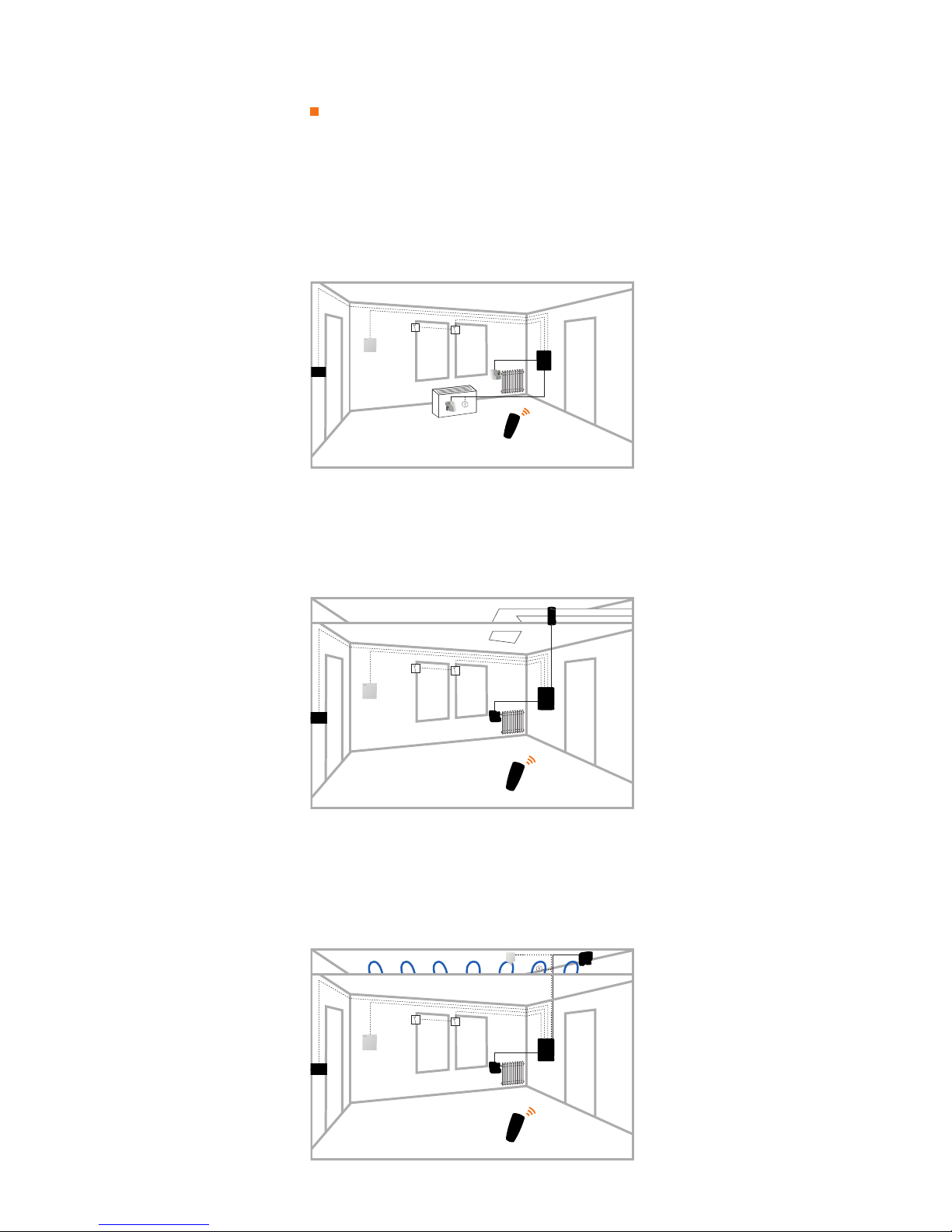
F
an coil, 2-pipe only cooling
– Valve actuator: ON/OFF
– Keycard contact
1. Thermostat: RDG100
2
. DIP switch: Application 2-pipe
Y
1 = ON/OFF
3. Wire: Actuator → Y1-N
F
an → Q1...Q3-N
Key card → D1-GND
4. Parameters: no change necessary (factory-setting)
TIPS
–
Keycard contact in hotel guest rooms helps saving energy costs
–
RDG100T with 7-day time program
– RDG100KN communicating KNX
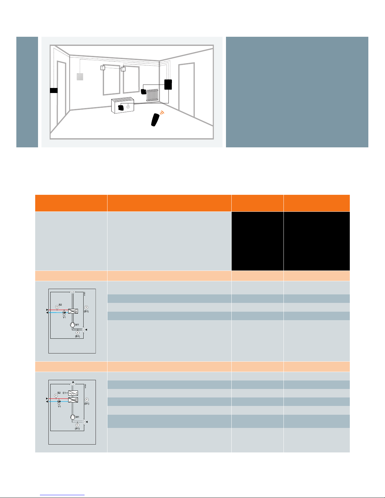
F
an coil, 2-pipe with el. heater
– Valve actuator: ON/OFF
– Heating with electrical heater ON/OFF
– Automatic changeover
– Return air temperature sensor
1. Thermostat: RDG110
2. DIP switch: Application 2-pipe, el. heater
3. Wire: Actuator → Y11-N
El. heater → Y21-N
Fan → Q1...Q3-N
Temp. sensor → X1-M
H/C CO sensor → X2-M
4. Parameters: P01 = 3 (Auto H/C CO)
TIPS
– RDG110 with relay outputs can drive direct an el. heater
up to 1 kW
Fan coil, 4-pipe with el. heater
– Valve actuators H&C: PWM
– Electrical heater: ON/OFF
– Electrical heater enable input
– Window contact
1. Thermostat: RDG100
2. DIP switch: Application 4-pipe, el. heater
Y1 = PWM
Y3 = PWM
3. Wire: Actuator H. → Y1-N
Actuator C. → Y3-N
Contactor
1
for el. heater → Y2-N
Fan → Q1...Q3-N
El. heater enable → X1-M
Window cont. → D1-GND
4. Parameters: P38 = 5 (El. heater Input)
P46 = 2 (PWM H.)
P47 = 2 (PWM C.)
TIPS
– Electrical heater enable signal for saving energy costs
– Note
1
: Add conductor if load exceed 1A!
Fan coil application
examples
Application examples
Installation and set up
1. Select a suitable thermostat
2. Set application via DIP switch according to the mounting Instructions
3. Wire and install the thermostat. Apply power
4. If necessary, set parameter P01 (control sequence) and other application-specific parameters
Page 25

25
Application How to set the application
F
an coil, 2-pipe and floor heating,
single speed
–
2-pipe cooling only: ON/OFF
– Floor heating limitation (ON/OFF)
w
ith temperature limitation
– Single speed fan
1
. Thermostat: RDG100
2. DIP switch: Application 2-pipe & rad.
Y
1 = ON/OFF
Y
3 = ON/OFF
3
. Wire: Actuator C. → Y1-N
A
ctuator H. → à Y3-N
Fan → Q1-N
F
loor temp. sensor. → X1-M
4. Parameters: P51 = 25°C (floor Heat. Temp. limit.)
P53 = 1 (Single-speed fan)
TIPS
– Floor heat limitation to avoid overheating (DIN EN 1264)
h
ence protect your floor and as well provides more comfort
– Select “2-pipe & el. heater” for application with electrical
floor heating
Fan coil, 4-pipe, ECM fan
– Valve actuators: DC 0…10 V
1. Thermostat: RDG160
2. DIP switch: Application 4-pipe
Y10 = DC 0…10 V
Y20 = DC 0…10 V
3. Wire: Actuator H → Y10-Go
Actuator C → Y20-Go
ECM fan → Y50-Go
4. Parameters: no changes necessary (factory-setting)
TIPS
– Modulating (ECM) fan control for optimal comfort, lower level
of noice and for saving energy costs
– Check ECM fan max (P55) and min (P56)
CLC and radiator
– Chilled ceiling (3-pos) and radiator (PWM)
– Dewpoint monitor
1. Thermostat: RDG100
2. DIP switch: Application 2-pipe & rad.
Y1/Y2 = 3-pos
Y3 = PWM
3. Wire: Actuator C → Y1/Y2-N
Actuator H → Y3-N
Dewpoint sens. → X1-M
4. Parameters: P38 = 4 (Dewpoint input)
P46 = 2 (PWM)
P52 = 0 (Fan disable)
TIPS
– Dewpoint monitoring to detect condensation.
Cooling is stopped if condensation occurs.
Universal application
example
Page 26

26
Application How to set the application
V
AV single duct, cooling only
– Damper actuator: 0…10 V
–
Window contact
1
. Thermostat: RDG400
2. DIP switch: Application single duct
Y
10 = DC 0...10 V
3. Wire: Actuator → Y10-Go-G
W
indow contact → D1-GND
4
. Parameters: no change (= default)
TIPS
–
Window contact for saving energy during airing the rooms
VAV single duct and el. reheater
–
Damper actuator: 3-pos
– El. heater: DC 0...10V
– Central time switch
1. Thermostat: RDG400
2
. DIP switch: Application single duct +
el. heater
Y10 = DC 0...10 V
3
. Wire: Actuator → Y1/Y2-Go
El. heater → Y10-Go
T
ime switch → D1-GND
4. Parameters: P47 = 1 (VAV output 3-pt)
T
IPS
– Use a central time switch (e.g. SEH62.1) to set back room
temperature during non-business hours
– Adjust parameter prolong comfort period (P68) to allow
occupant to override the central time switch, e.g. by working
overtime
Compressor with reverse valve
– Compressor: ON/OFF
– Reverse valve: ON/OFF
1. Thermostat: RDG110
2. DIP switch: Application 4-pipe
3. Wire: Compressor → Y11/Y21-N
RV → Y12/Y22-N
4. Parameters: P52 = 0 (Fan disable)
– Set control sequence to manual change over (P01=2);
then the user can select manually between heating or cooling
VAV application examples
HP application example
Page 27

27
Notes
Page 28

28
Application Functionality
Over view – fan coil room thermostats
2-pipe/heating only
2-pipe/cooling only
2-pipe/heating or colling
2-pipe with el. heater
2-pipe and radiator
4-pipe/cooling & heating
4-pipe with el. heater
2-stage/heating or cooling
Control algorithm
Manual heat-cool changeover
Automatic heat-cool changeover
Floor heating limitation
Manual fan speed off / I / II / III
Automatic fan control
Ventilation function
Electronic Commutated fan Motor
5
7-day time programm
Fan operation enable/disable
Infrared remote control
Basic
R
AB10
RAB10.1
R
AB10.2
RAB20
R
AB20.1
RAB30
RAB30.1
R
AB40.1
RAB90
RAB90.1
Modern
RCC10
RCC10.1
RCC20
RCC30
RCC50.1
RCC60.1
Advance: Semi flush-mounted
RDF300
RDF300.02
RDF310.2
RDF310.21
RDF340
RDF400.01
RDF410.21
Advanced: Wall-mounted
RDF110
RDF110.2
RDF210
RDF210.2
RDG100
RDG100T
RDG110
RDG140
RDG160
Communicating:
Semi flush-mounted
RDF301
RDF301.50
Communicating: Wall-mounted
RDG100KN
2P
2
P
2P
2
P
2P
2P
2
P
2P
No
No
2P
2P
2P
2P
PI
PI
2P/PI
2P/PI
2P
2P
P/PI
2P/PI
2P
2P
2P
2P
2P
2P/PI
2P/PI
2P
P/PI
P/PI
2P/PI
2P/PI
2P/PI
4
4
4
2
2
2
2
(X): X = number of outputs
1
Either on/off, 3-pos or PWM signals
2
Infrared remote control optional (...x10/IR)
3
Either return air temp. sensor or heat-cool changeover sensor
4
With external aquastat
5
ECM DC 0...10V fan control
Page 29

29
Outputs Inputs
Power supply
User interface
Light and blind control
Communication interface KNX
On/Off
PWM
3-position
DC 0...10 V
Multifunctional inputs
Operating mode switch-over contact
Return air temperature sensor
Heat-cool changeover sensor
Power supply
Setpoint knob
Setpoint buttons
Fan speed switch
Fan speed button
Operating mode button
Display (LCD), indicator (LED)
Backlight
Additional operation selector/remarks
(1)
(1)
(1)
(1)
(1)
(2)
(2)
(1)
(1)
(1)
(2)
(2)
(2)
1
(2)
1
(1)
(1)
(2)
1
(1)
(1)
(1)
(1)
(1)
(3)
1
(3)
1
(2)
(2)
1
(2)
1
(3)
1
(2)
1
(2)
1
(2)
1
(1)
(1)
1
(1)
1
(1)
1
(2)
1
(2)
1
(1)
1
(1)
1
(2)
1
(1)
(2)
(2)
(2)
AC 24..250 V
AC 24..250 V
AC 24..250 V
AC 24..250 V
AC 24..250 V
AC 24..250 V
AC 24..250 V
AC 24..250 V
AC 24..250 V
AC 24..250 V
AC 230 V
AC 230 V
AC 230 V
AC 230 V
AC 24 V
AC 230 V
AC 230 V
AC 230 V
AC 230 V
AC 230 V
AC 24 V
AC 230 V
AC 230 V
AC 230 V
AC 230 V
AC 230 V
AC 230 V
AC 230 V
AC 230 V
AC 230 V
AC 24 V
AC 24 V
AC 230 V
AC 230 V
AC 230 V
LED
LED
LED
LED
LED
LED
LCD
LCD
LCD
LCD
LCD
LCD
LCD
LCD
LCD
LCD
LCD
LCD
LCD
LCD
LCD
LCD
LCD
LCD
LCD
Heat-cool co switch
Vent-heat-cool switch
Heat-cool co switch
Heat/cool-vent switch
Heat-cool co switch
Heat-vent-cool co switch
Cool (compressor)-vent-off switch
Manual output switch
Heat-cool button
Heat-cool button
Time-prog buttons
Heat-cool button, time-prog buttons
Heat-cool button
Time-prog buttons
Heat-cool button, time-prog buttons
Time-prog buttons
Light and blind buttons
333
3
Page 30

3030
Application Functionality
Overview – universal room thermostats
Basic
RAA10
RAA20
RAA200
RAA30
RAA40
Modern
RCU10
RCU10.1
RCU15
RCU20
RCU50
RCU50.2
RLA162
Advanced
RDU340
4
RDG400
RDG100-line
5
RDX33.21
RDX43.2
Communicating
RDU341
4
RDG400KN
RDG100KN
5
2P
2P
2P
2P
2P
2P/PI
2P/PI
2P/PI
PI
P
P
PI
P/PI
P/PI
2P/PI
2P
2P
P/PI
P/PI
2P/PI
6
6
1
External setpoint shift by 0 to 10V input
2
External setpoint shift by outdoor temperature sensor
3
Either ON/OFF, 3-position or PWM signal
4
Semi flush-mounted thermostats
5
RDG100 line (fan coil units) thermostats are also suited for chilled ceiling and radiator applications. For detailed information, refer to the fan coil unit overview.
6
Only with Vmin limitation
7
External setpoint shift via KNX
8
E.g. window contact of key card reader
(X):X = number of outputs
Universal
VAV/CAV
Heat pumps
Heating only
Cooling only
Heating or cooling
Heating and cooling
2-stage heating
2-stage heating or cooling
Cooling or heating & el. heating
Control algorithm
Automatic heat-cool changeover
Manual heat-cool changeover
Vmin, Vmax limitation of supply air
Floor heating limitation
Dewpoint monitoring
Infrared remote control
7-day time program
Communication interface KNX
Page 31

3131
Outputs Inputs Power supply User interface
(1)
(1)
(1)
(1)
(1)
(2)
3
(2)
3
(2)
3
(1)
(1)
3
(3)
3
(2)
(3)
(1)
(1)
3
(3)
3
(2)
3
(2)
3
(2)
3
(1)
3
(2)
3
(1)
3
(2)
3
(1)
(1)
3
(2)
3
(1)
3
(2)
3
(1)
(1)
(2)
(1)
(1)
(1)
(1)
1
2
7
7
7
AC 24..250 V
AC 24..250 V
AC 24..250 V
AC 24..250 V
AC 24..250 V
AC 230 V
AC 230 V
AC 24 V
AC 230 V
AC 24 V
AC 24 V
AC 24 V
AC 24 V
AC 24 V
AC 230 V
Batt.
AC 230 V
AC 24 V
AC 24 V
AC 230 V
S
B
B
B
B
B
B
B
B
LCD
LCD
LCD
LCD
LCD
LCD
LCD
LCD
Large setting knob
ON/OFF switch
Heat/of f/cool switch
Heat/of f/cool switch
Time-prog buttons
Manual CO button, time-prog buttons
Manual CO button, time-prog buttons
On/Off
PWM
3-position
DC 0...10 V
Output H/C changeover
Operating mode switch-over contact
Heat-cool changeover sensor
Remote or return air temperature sensor
External setpoint shift
Power supply
Setpoint knob
Setpoint buttons
Operating mode button (B)/switch (S)
Digital display (LCD), indicator (LED)
Additional operation selector/remarks
 Loading...