

Page 1

CE1N3036en
13.10.2008
Building Technologies
3
036
Room Temperature Controller
with 7-Day Time Switch, LCD and
opt. Remote Temperature Sensor
RDE20.1
for heating systems
2-position control with ON/OFF output for heating
Operating modes: normal operation and energy saving mode
7-day time switch and manual operation
Battery-powered DC 3 V
Input for external temperature sensor
Use
The RDE20.1 is used for the control of the room temperature in heating systems.
Typical applications:
• Apartments
• Commercial spaces
• Schools
For the control of the following pieces of equipment:
• Thermic valves or zone valves
• Gas or oil burners
• Fans
• Pumps
Page 2
2/8
Siemens Room temperature controllers CE1N3036en
Building Technologies 13.10.2008
Functions
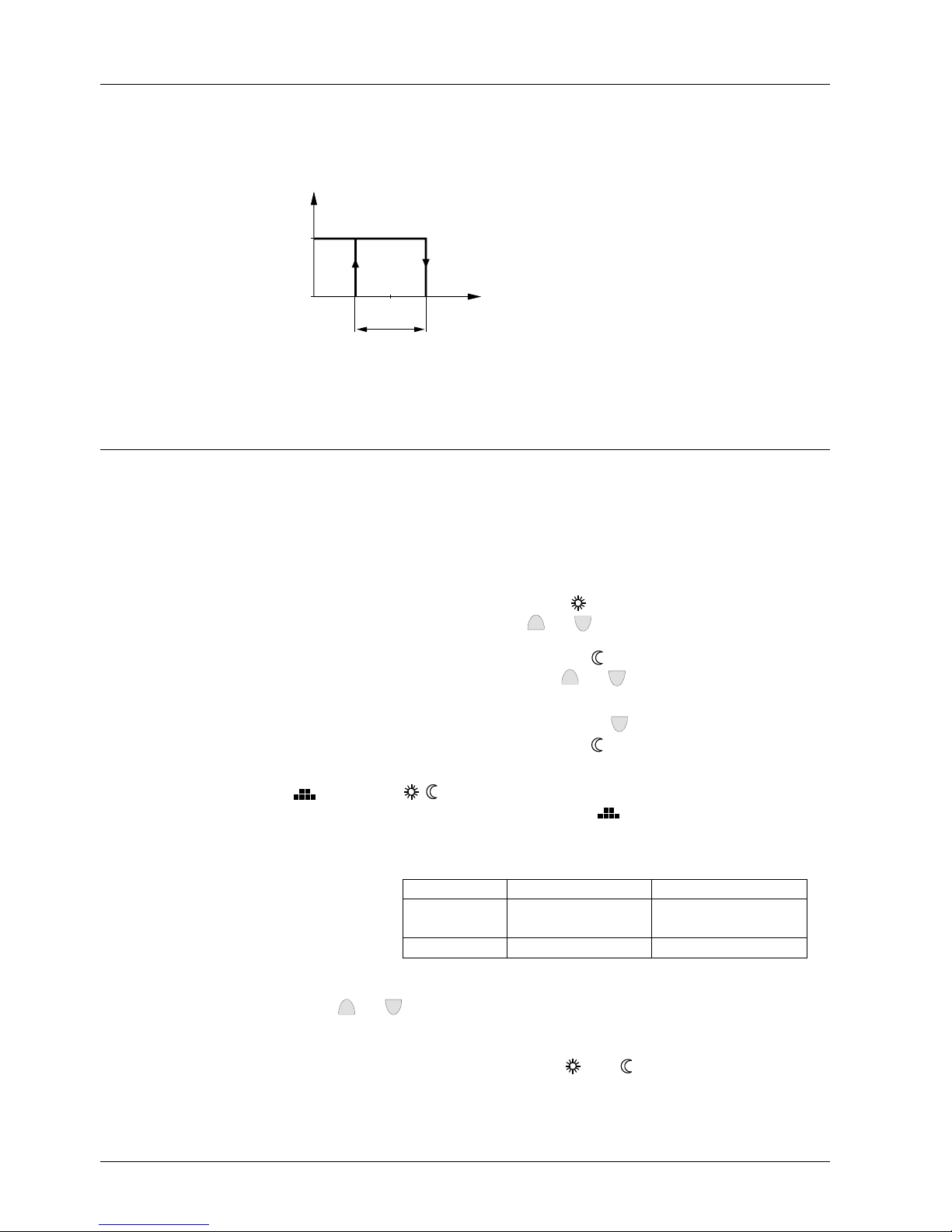
The controller acquires the room temperature with its integrated sensor or external
room temperature sensor (QAA32) or external return air temperature sensor (QAH11) –
if used – and maintains the setpoint by delivering control commands. The switching
differential is 1 K.
Q14
T[°C]
ON
OFF
W
SD
3030D01
T Room temperature
SD Switching differential
W Room temperature setpoint
Q14 Output signal for heating
The RDE20.1 can provide control either according to the internal room temperature or
according to a remote temperature. The controller detects automatically when a QAH11
is connected. In this case, the internal temperature sensor is deactivated.
Operating modes
The RDE20.1 provides normal operation and, optionally, energy saving mode or OFF.
The difference between normal operation and energy saving mode is only the room
temperature setpoint. The changeover between the operating modes can be made
either automatically according to the 7-day time switch or manually with the operating
mode selector.
When normal operation is activated, symbol “
“ appears on the display. The setpoint
can be readjusted by pressing buttons
+
and -.
When energy saving mode is activated, symbol “
“ appears on the display. The set-
point can be readjusted by pressing buttons
+
and
-
.
In energy saving mode, the unit can also be switched to “Off”. This is accomplished by
selecting a setpoint of 5 °C and then keeping button
-
depressed for 4 seconds. In
that case, the “OFF“ will appear and the symbol “
“ does not appear.
The changeover between the operating modes can take place either automatically
(
) or manually ( , ), depending on the position of the operating mode selector.
When the operating mode selector is in position “
”, changeover will take automatically according to the selected switching pattern. For every weekday, a specific switching pattern can be selected.
Factory setting:
Day(s) Normal operation Energy saving mode
Mo (1) – Fr (5) 6:00 – 8:00 h and
17:00 – 22:00 h
22:00 – 6:00 h and
08:00 – 17:00 h
Sa (6) – Su (7) 7:00 – 22:00 h 22:00 – 7:00 h
The current setpoint can be temporarily readjusted by pressing
buttons
+
and
-
. The setpoint will then be reset to its initial value the next time auto-
matic or manual changeover takes place.
When the operating mode selector is set to “
“ or “ “, the RDE20.1 will maintain
normal operation or energy saving mode respectively.
Function diagram
Remote temperature
sensor
Normal operation
Energy saving mode
or OFF
7-day time switch
Page 3
3/8
Siemens Room temperature controllers CE1N3036en
Building Technologies 13.10.2008
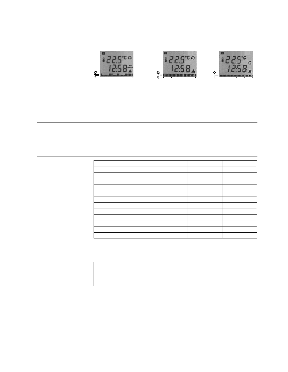
The digital display shows the actual room temperature, the time of day, the weekday,
the current switching pattern and the symbol of the operating mode currently active.
The switching pattern shows normal operation as a double bar and energy saving
mode as a single bar with a flashing time pointer. When the heating output is activated,
the triangle symbol appears.
0 6 12 18 24
0 6 12 18 24
0 6 12 18 24
Automatic changeover according Normal operation Energy saving mode
to the switching pattern
When taking out the batteries, the setpoints and the information required for operating
mode changeover are retained for 3 minutes.
Ordering
When ordering, please give name and type reference: room temperature controller
RDE20.1.
Sensor and valve actuators are to be ordered as separate items.
Equipment combinations
Type of unit Type reference Data sheet
Temperature sensor
QAH11
1840
Room sensor
QAA32
1747
Electromotoric actuator
SFA21...
4863
Electrothermal actuator (for radiator valve)
STA21...
4877
Electrothermal actuator (for small valve 2,5 mm)
STP21...
4878
2-port and 3-port zone valves
MXI/MVI421…
4867
Electromotoric actuator for zone valve V..146..
SUA21
4830
Electric actuator
SUA11/22
4832
Air damper actuator
GDB…
4624
Air damper actuator
GSD/GQD…
4606
Rotary damper actuators
GXD…
4622
16A extension relay module
SEZ16
-
Accessories
Description Type reference
Adapter plate 120 x 120 mm for 4“ x 4“ conduit boxes ARG70
Adapter plate 96 x 120 mm for 2“ x 4“ conduit boxes ARG70.1
Adapter plate for surface wiring 112x130 mm ARG70.2
Display
Backup
Page 4

4/8
Siemens Room temperature controllers CE1N3036en
Building Technologies 13.10.2008
Mechanical design
The unit consists of two parts:
• A plastic housing with digital display, which accommodates the electronics, the
operating elements and the built-in room temperatures sensor
• A mounting base
The housing engages in the mounting base and snaps on.
The base carries the screw terminals.
3035Z01
1 Display of the room temperature in °C or setpoints
2 Current time of day using the format 00:00 ... 23:59
3 Current weekday from 1 (Monday) to 7 (Sunday)
4 Current switching pattern with flashing time pointer
5
symbol when actual room temperature is displayed
6
Normal operation
Energy saving mode
7
symbol in automatic mode or when selecting the switching pattern
8
heating on
9
symbol indicating that batteries need to be replaced
10 Buttons for adjusting the setpoints, the time of day and the switching times
11 Operating mode selector
12 Setting the weekday
13 Setting the time of day
14 Selecting and leaving the setting mode for the switching pattern
15 Setpoint adjustment for energy saving mode
16 Setpoint adjustment for normal operation
17 Button for confirming the switching pattern settings
18 Battery compartment
Legend
Page 5

5/8
Siemens Room temperature controllers CE1N3036en
Building Technologies 13.10.2008
Notes
The room temperature controller should be mounted in a location where the air temperature can be measured as accurately as possible without getting adversely affected
by direct solar radiation or other heat or refrigeration sources.
Mounting height is about 1.5 m above the floor.
The unit can be fitted to a recessed conduit box.
• Only authorised staff may open the controller.
Caution: The switching output voltage is from AC24V up to AC250V
• The cables used must satisfy the insulation requirements with regard to mains
potential
When mounting the unit, fix the baseplate first. Then, make the electrical connections
and fit and secure the cover (also refer to separate Mounting Instructions).
The controller must be mounted on a flat wall and in compliance with local regulations.
If there are thermostatic radiator valves in the reference room, they must be set to their
fully open position.
The controller is maintenance-free.
If the temperature on the display does not agree with the room temperature effectively
measured, the temperature sensor can be recalibrated. For that purpose both buttons
+
and must be pressed simultaneously for 3 seconds. Then, the temperature
displayed can be changed by a maximum of +/- 10 K by pressing the
+
and- but-
tons. Five seconds after the last push of a button, the controller will automatically return
to the normal operational status.
The setpoint limitation is used in some specific applications where the setpoint temperature is required to be above 35°C (Less than 60°C). For that purpose both buttons
+
and- must be pressed simultaneously for 5 seconds. The top row of the LCD will
then display 35°C to signify the default setpoint limitation whereas the bottom row will
display SPLt to signify the setpoint limitation mode. The temperature limitation can be
changed by pressing the
+
and- buttons. Five seconds after the last push of a but-
ton, the controller will automatically saved the value and return to the normal operational status.
If the battery symbol appears, the battery power is almost exhausted and the batteries
should be replaced. Only AAA alkaline batteries have to be used.
To reset, first press and hold the button
, then press the two buttons
+
-
simultane-
ously for 3 seconds. All individual settings will be reset to their standard values.
Mounting, installations and commissioning
Maintenance
Sensor calibration
Setpoint limitation
Change of batteries
Reset
Page 6

6/8
Siemens Room temperature controllers CE1N3036en
Building Technologies 13.10.2008
Technical data
Operating voltage DC 3 V (2 x 1.5 V AAA Alkaline batteries)
Battery life (RDE20.1) > 1 years (AAA Alkaline batteries)
Supply line fusing max. 10 A
External:
External temperature sensor QAH11/QAA32, Safety class II
(Inputs B1, M) NTC resistor 3 kΩ at 25°C
Permissible cable length for max. 20 m, copper cable, 1.5 mm
2
External sensor (Terminal B1)
Tolerance max. ± 2.5°C
Internal:
Thermistor 10 kΩ ± 1% at 25°C
Relay Contacts
Switching voltage max. AC 250 V
min. AC 24 V
Switching current max. 5A res., 2 A ind.
At 250 V min. 50 mA
Contact life at AC 250 V guide values:
At 0.1 A res. 2 x 10⁶ cycles
At 0.5 A res. 1 x 10
6
cycles
At 4 A res. 1.5 x 10
5
cycles
No load 5 x 10
7
cycles
Insulating strength
Between relay contacts and coil AC 3750 V for 6 sec.
AC 2000 V for 60 sec.
Between relay contacts (same pole) AC 1000 V for 60 sec.
Switching differential SD 1 K
Setpoint setting range 5…35 °C (normal operation)
5…60 °C (with setpoint limitation)
0 (OFF) and 5…35 °C (energy saving mode)
Factory setting normal operation 20 °C
Factory setting energy saving mode 8 °C
Resolution of settings and displays
Setpoints 0.5 °C
Switching times 60 min
Actual value displays 0.5 °C
Time of day displays 1 min
Setpoint Limitation range 35…60 °C
Factory setting setpoint limitation 35 °C
Resolution for setpoint limitation 0.5 °C
Connection terminals screw clamp terminals
(via mounting plate)
For solid wires 2 x 1.5mm
2
For stranded wires 1 x 2.5mm
2
(Minimum 0.5 mm2)
Operation to IEC 721-3-3
Climatic conditions class 3K5
Temperature 0…+50 °C
Humidity <95 % r. h.
Power supply
Sensor inputs
Outputs
Switching Outputs
(Q11, Q12, Q14)
Operational data
Electrical connections
Environmental conditions
Page 7

7/8
Siemens Room temperature controllers CE1N3036en
Building Technologies 13.10.2008
Transport to IEC 721-3-2
Climatic conditions class 2K3
Temperature -25…+60 °C
Humidity <95 % r. h.
Mechanical conditions class 2M2
Storage to IEC 721-3-1
Climatic conditions class 1K3
Temperature -25…+60 °C
Humidity <95 % r. h.
conformity to
EMC directive 2004/108/EC
Low voltage directive 2006/95/EC
N474
C-Tick conformity to
EMC Requirement AS/NZS 4251.1: 1999
Product standards
Automatic electrical controls for EN 60 730- 1 and
household and similar use EN 60 730- 2-9
Electromagnetic compatibility
Emissions (industrial sector)
EN 61000-6-3
Immunity (domestic sector, light ind.)
EN 61000-6-1
Safety class II to EN 60730
Pollution degree 3
Degree of protection of housing IP30 to EN 60529
Weight 0.21 kg
Colour of housing front white, RAL 9003
Housing material ABS (Slider: POM, LCD Lens: GP PS)
Connection diagram
Application examples
T
T
F1
F2
N1
M1
Y2
2222S01
T
T
F1
F2
N1
M1
Y2
2222S02
T T
Room temperature controller with direct Room temperature controller with direct
Norms and standards
General
B1 QAH11 external temperatures sensor
N1 RDE20.1 room temperature controller
Y1 Regulating unit
L, N Live, Neutral AC 24...250 V
B1 Signal input “External temperature sensor”‘
F1 External fuse
M Measuring neutral “External temperature
sensor”‘
Q11, Q12 N.C. contact ( for N.O. valves)
Q11, Q14 N.O. contact ( for N.C. valves)
3V
Q11
Q12
Q14
Y1 B1
L
N
F1
M
B1 N1
Page 8

8/8
Siemens Room temperature controllers CE1N3036en
Building Technologies 13.10.2008
control of a gas-fired wall-hung boiler control of a gas-fired floor-standing boiler
T
N1
Y1
2222S03
M1
Room temperature controller with direct
control of a heating circuit pump (precontrol
by manual mixing valve)
F1 Thermal reset limit thermostat
F2 Safety limit thermostat
M1 Circulating pump
N1 RDE20.1 room temperatures controller
Y1 3-port valve with manual adjustment
Y2 Magnetic valve
Dimensions
96
119
23,8
3035M01
89,45
4
3035M02
28 28
28
28
26
30
3530
11,8
112,3
4
Controller
Baseplate
© 2003 - 2008 Siemens Building Technologies AG Subject to change
 Loading...