

Page 1
031
3
Room Temperature Controllers
RDD10...
with LCD
for heating systems
2-position control with ON / OFF output for heating
Operating modes: normal operation and energy saving mode
Automatic operating mode change over as an option
Mains-powered AC 230 V (RDD10) or battery-powered DC 3 V (RDD10.1)
Use
CE1N3031en
24.09.2003
The RDD10... is used for the control of the room temperature in heating systems.
Typical applications:
• Apartments
• Commercial spaces
• Schools
For the control of the following pieces of equipment:
• Thermic valves or zone valves
• Gas or oil burners
• Fans
• Pumps
Siemens Building Technologies
HVAC Products
Page 2
Functions
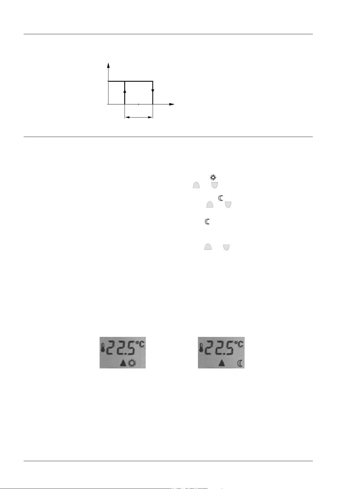
The controller acquires the room temperature with its integrated sensor and maintains
the setpoint by delivering control commands. The switching differential is 1 K.
Operating modes
Normal operation
Energy saving mode
or OFF
Automatic operating
mode change over
Display
ON
OFF
Q14
W
SD
3031D01
T[°C]
T Room temperature
SD Switching differential
W Room temperature setpoint
Q14 Output signal for heating
The RDD10... provides normal operation and, optionally, energy saving mode or OFF.
The difference between normal operation and energy saving mode is only the room
temperature setpoint. The changeover from normal operation to energy saving mode,
and vice versa, is made by pressing a button.
When normal operation is activated, symbol “
can be readjusted by pressing buttons
+
When energy saving mode is activated, symbol “
point can be readjusted by pressing buttons
“ appears on the display. The setpoint
-
and
.
“ appears on the display. The set-
+
and
-
. When the energy saving setpoint is set to “ 0 ”, the controller is switched off, that is, the RDD10... is not active in
energy saving mode. In that case, symbol “
“ does not appear.
When this function is activated and a manual changeover has been made, the operating mode will automatically be reset on completion of an adjustable period of time. This
period of time can be adjusted with buttons
+
and
-
after pressing the hour glass
button.
The operating action of the reset depends on the setting of the DIL switch, from normal
operation to energy saving mode / OFF, or vice versa. The operating mode can be
manually reset before the delay time has elapsed. When the delay is active, the hour
glass symbols appears on the display.
The digital display shows the actual room temperature and the symbol of the operating
mode currently active. When the heating output is activated, the triangle symbol appears. When the function “automatic operating mode change over” is activated, the
hour glass symbol is shown.
Display in normal operation Display in energy saving mode
2/8
Siemens Building Technologies Room temperature controllers CE1N3031en
HVAC Products 24.09.2003
Page 3
Type summary
Type reference Features
Ordering
Equipment combinations
Accessories
Mechanical design
RDD10
RDD10.1
Mains-powered AC 230 V
Battery-powered DC 3 V
When ordering, please give name and type references, e.g. room temperature con-
troller RDD10.
Valve actuators are to be ordered as separate items.
Type of unit Type reference Data sheet
Motoric on/off actuator
Thermal actuator (for radiator valve)
Thermal actuator (for small valve 2,5 mm)
SFA21...
STA21...
STP21...
4863
4893
4878
.
.
Description Type reference
Adapter plate 120 x 120 mm for 4“ x 4“ conduit boxes ARG70
Adapter plate 96 x 120 mm for 2“ x 4“ conduit boxes ARG70.1
Adapter plate for surface wiring 112x130 mm ARG70.2
.
.
.
.
.
.
.
The unit consists of two parts:
• A plastic housing with digital display, which accommodates the electronics, the
operating elements and the built-in room temperatures sensor
• A mounting base
The housing engages in the mounting base and snaps on.
The base carries the screw terminals. The DIP switch is located at the rear of the housing.
3031Z01
3/8
Siemens Building Technologies Room temperature controllers CE1N3031en
HVAC Products 24.09.2003
Page 4

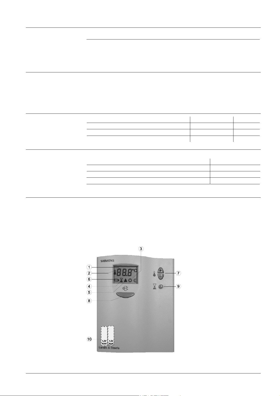
Legend
1 Display of the room temperature, setpoints or operating mode changeover time
symbol when actual room temperature is displayed
2
3
Normal operation
Energy saving mode
4
symbol when displaying the operating mode changeover time or when the oper-
ating mode changeover function is activated
5
heating on
6
symbol indicating that batteries need to be replaced
(only with battery-powered versions)
7 Buttons for adjusting the setpoint and the operating mode changeover time
8
Button for operating mode changeover “Normal operation ↔ energy saving
mode”
9 Button for adjusting the operating mode changeover time
10 Battery compartment (only with battery-powered versions)
The required room temperature setpoints for normal operation and energy saving mode
and the operating mode changeover time are adjusted with buttons. Operating mode
changeover can be triggered by pressing a button.
The operating action for the automatic operating mode changeover function is selected
with a DIP switch.
Notes
DIP switch
no.
1
Meaning Position ON Position OFF
Operating action of
automatic operating
mode changeover
Automatic operating
mode changeover from
normal operation to energy saving mode or OFF
Automatic operating
mode change over from
energy saving mode or
OFF to normal operation
The room temperature controller should be mounted in a location where the air temperature can be measured as accurately as possible without getting adversely affected
by direct solar radiation or other heat or refrigeration sources.
Mounting height is about 1.5 m above the floor.
The unit can be fitted to a recessed conduit box.
• Only authorised staff may open the controller.
Caution: AC 230 V!
• The cables used must satisfy the insulation requirements with regard to mains
potential
Mounting, installation
and commissioning
When mounting the unit, fix the baseplate first. Then, make the electrical connections
and fit and secure the cover (also refer to Mounting Instructions).
The controller must be mounted on a flat wall and in compliance with local regulations.
4/8
Siemens Building Technologies Room temperature controllers CE1N3031en
HVAC Products 24.09.2003
Page 5

Maintenance
Sensor calibration
Change of batteries
(only with batterypowered versions)
Technical data
If there are thermostatic radiator valves in the reference room, they must be set to their
fully open position.
The controller is maintenance-free.
If the temperature on the display does not agree with the room temperature effectively
measured, the temperature sensor can be recalibrated. For that purpose, both buttons
+
and must be pressed simultaneously for 3 seconds. Then, the temperature
+
displayed can be changed by a maximum of +/- 3 Kelvin by pressing the
and -
buttons. Five seconds after the last push of a button, the controller will automatically
return to the normal operational statuses.
If the battery symbol appears, the battery power is almost exhausted and the batteries
should be replaced.
Power supply
Control outputs
Functional data
Environmental conditions
Operating voltage
• RDD10 at L - N AC 230 V +10/-15 %
• RDD10.1 DC 3 V (2 x 1.5 V AAA Alkaline batteries)
Frequency (RDD10) 50 or 60 Hz
Power consumption (RDD10) 4VA
Battery life (RDD10.1) > 1 years (AAA Alkaline batteries)
Control output Q12 (N.C. contact)
Rating RDD10 (AC 230 V) max. 5 A
Rating RDD10.1 (AC 24...250 V) max. 5(2) A
Control output Q14 (N.O. contact)
Rating RDD10 (AC 230 V) max. 5 A
Rating RDD10.1 (AC 24...250 V) max. 5(2) A
Switching differential SD 1 K
Setpoint setting range 5…35 °C (normal operation)
0 (OFF) and 5…35 °C (energy saving mode)
Increments 0.5 °C
Factory setting normal operation 20 °C
Factory setting energy saving mode 8 °C
Setting range of operating mode
changeover time 0.5…24 h
Increment 0.5 h
Factory setting 0 h (not activated)
Operation to IEC 721-3-3
Climatic conditions class 3K5
Temperature 0…+50 °C
Humidity <95 % r. h.
Transport to IEC 721-3-2
Climatic conditions class 2K3
Temperature -25…+60 °C
Humidity <95 % r. h.
Mechanical conditions class 2M2
Storage to IEC 721-3-1
Climatic conditions class 1K3
Temperature -25…+60 °C
Humidity <95 % r. h.
5/8
Siemens Building Technologies Room temperature controllers CE1N3031en
HVAC Products 24.09.2003
Page 6

Norms and standards
General
conformity to
EMC directive 89/336/EEC
Low voltage directive 73/23/EEC and 93/68/EEC
N474
C-Tick conformity to
EMC emission standard
AS/NSZ 4251.1:1994
Product standards
Automatic electrical controls for EN 60 730 – 1 and
household and similar use EN 60 730 – 2 - 9
Electromagnetic compatibility
Emissions EN 50 081-1
Immunity EN 50 082-1
Safety class II to EN 60730
Pollution class normal
Degree of protection of housing IP30 to EN 60529
Connection terminals for use solid wires or prepared stranded wires
2
2 x 1.5 mm
or 1 x 2.5 mm2 (min. 0.5 mm2)
Weight 0.20 kg
Colour of housing front white, NCS S 0502-G (RAL9003)
6/8
Siemens Building Technologies Room temperature controllers CE1N3031en
HVAC Products 24.09.2003
Page 7

Connection diagram
Application examples
L
L
N
Q12
Ln
Q11
Q14
L
N1
Y1
N
N
Lx
3031A02
Q11
3V
Q12
3031A01
Nx
Q14
N1
Y1
RDD10 RDD10.1
N1 Room temperature controller
Y1 Regulating unit
L, Ln Live, AC 230 V
N Neutral, AC 230 V
Lx Live, AC 24 ... 250 V
Q11, Q12 N.C. contact (for N.O. valves)
Q11, Q14 N.O. contact (for N.C. valves)
Nx Neutral, AC 24 ... 250 V
T
M1
N1
2222S01
T
F1
T
F2
Y2
Room temperature controller with direct
control of a gas-fired wall-hung boiler
T
N1
Y1
M1
2222S03
Room temperature controller with direct
control of a heating circuit pump (pre-control
by manual mixing valve)
F1 Thermal reset limit thermostat
F2 Safety limit thermostat
M1 Circulating pump
T
N1
F2
F1
T T
Y2
M1
2222S02
Room temperature controller with direct
control of a gas-fired floor-standing boiler
N1 RDD10... room temperatures controller
Y1 3-point valve with manual adjustment
Y2 Magnetic valve
7/8
Siemens Building Technologies Room temperature controllers CE1N3031en
HVAC Products 24.09.2003
Page 8

Dimensions
Controller
Baseplate
3031M01
119
96
23,8
4
28 28
3530
2828
4
112,3
11,8
26
89,45
30
3031M02
8/8
Siemens Building Technologies Room temperature controllers CE1N3031en
HVAC Products 24.09.2003
2003 Siemens Building Technologies AG Subject to alteration
 Loading...