

Page 1
s
5
2
.
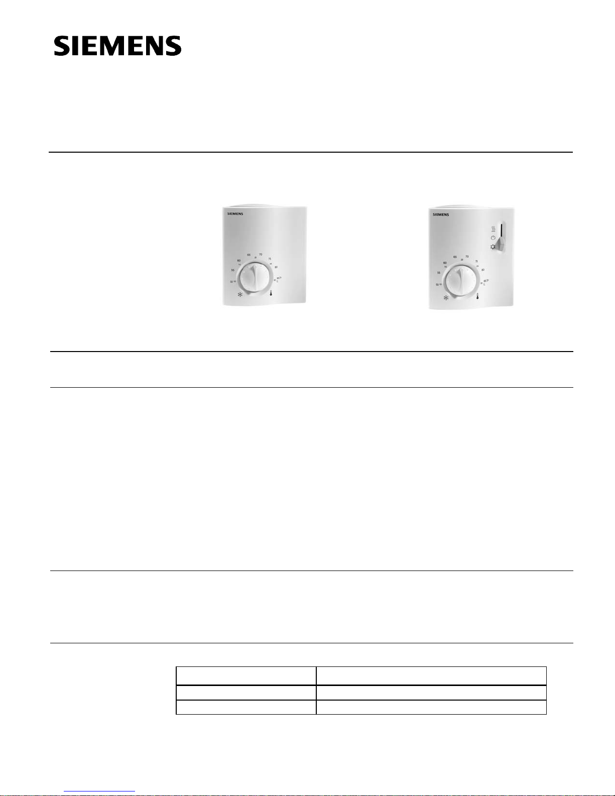
RCU50U and RCU50.2U
Room Temperature Controllers for
CAV Systems
Technical Instruction
Document No. 155-327P2
Rev. 1, March, 200
Description
Features
Application
RCU50U
The RCU microprocessor controlled CAV room controller is designed for air only, or air
and water heating and/or cooling systems. Controllers have proportional response.
• Modulating P-control
• 0 to 10 Vdc output for heating or cooling
• Automatic heating/cooling changeover (RCU50U)
• Manual heating/cooling changeover (RCU50.2U)
• Operating modes: Normal, Energy Saving, Frost Protection and Standby (RCU50U)
• Operating modes: Normal and OFF (RCU50.2U)
• Active 0 to 10 Vdc input for set point shifting (RCU50U)
• Operating mode changeover input for remote control (RCU50U)
• Adjustable minimum limitation for cooling output (RCU50U)
• Operating voltage 24 Vac
Controlling individual room temperature in HVAC installations that are heated or cooled
Controlling these types of equipment:
• Valve actuators
RCU50.2U
• Air damper actuators
Product Numbers
Product Numbers Features
NOTE:
Table 1.
RCU50U Without operating mode selector
RCU50.2U With manual heating/cooling changeover switch
To order without logo, change suffix to "/U/NL".
Example:
Siemens Building Technologies, Inc.
RCU50/U/NL.
Page 2
Technical Instructions RCU50U and RCU50.2U Room Temperature Controllers
r
l
0
Document Number 155-327P25 for CAV Systems
Rev. 1, March, 2002
Ordering
The temperature sensor, changeover mounting kit, and valve and damper actuators
must be ordered separately.
Table 2. Equipment Combinations.
Function
Heating-Cooling with
Minimum Limitation
Cooling
Product Numbe
Description Technical Instructions
QAH11.1 Temperature sensor 155-329P25
GDE16… 44 lb-in NSR Air damper actuator
155-187P25
GLB16… 88 lb-in NSR Air damper actuator
SSB61U Valve actuator 155-192P25
SSC61U
Valve actuator 155-313P25
SSC61.5U
SQS65U
Valve actuator 155-190P25
SQS65.5U
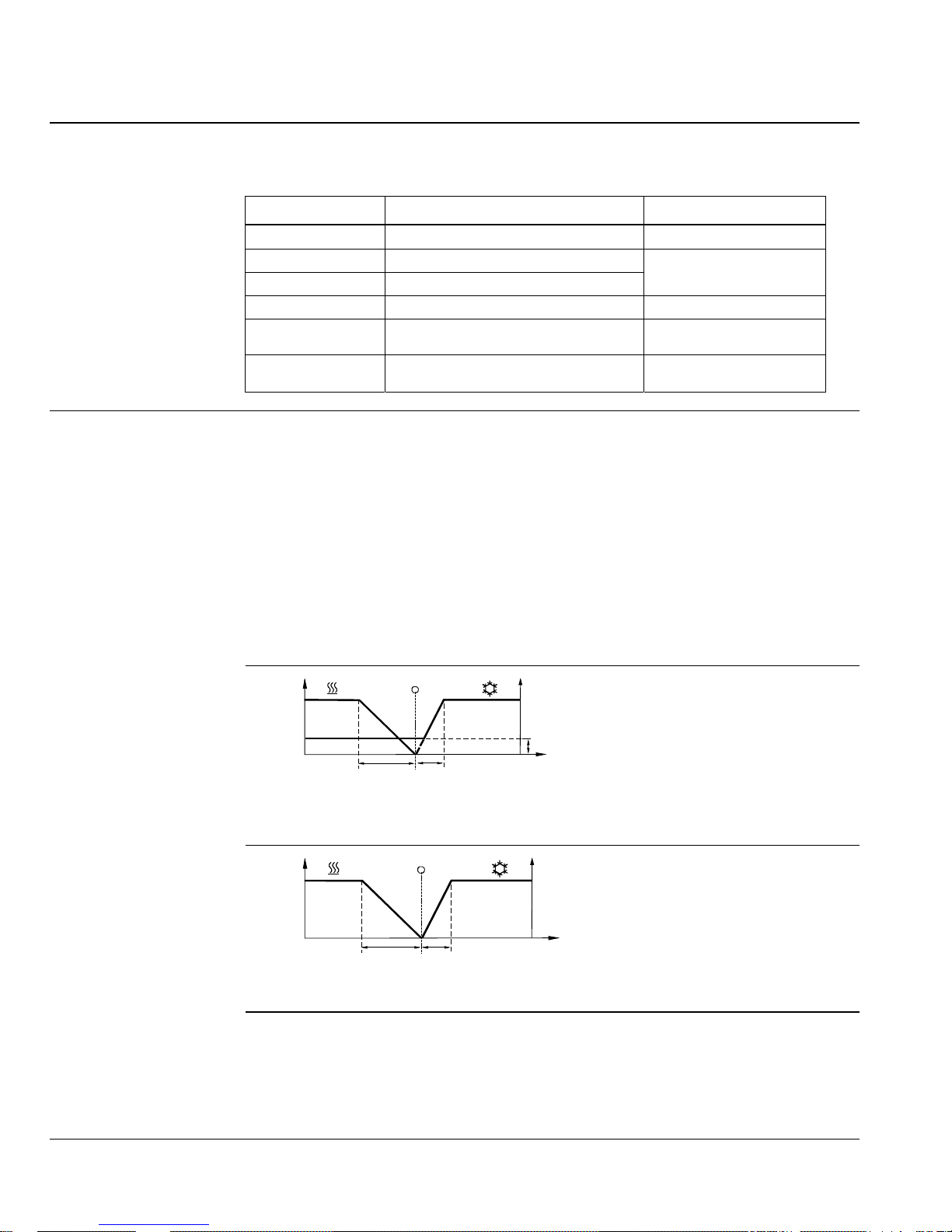
The controller measures the room temperature with its integrated sensor and maintains
the set point by delivering 0 to10 Vdc control commands. The RCU50U and RCU50.2U
provide P-control. With the RCU50U, the proportional band can be 2°F or 7°F (1°C or
4°C) in heating mode and 1°F or 3.5°F (0.5°C or 2°C) in cooling mode (selectable with
DIP Switch No. 4). With the RCU50.2U, the proportional band is fixed, 7°F (4°C) in
heating mode and 3.5°F (2°C) in cooling mode.
• RCU50U – When in the heating mode, on increase in temperature, the output signa
goes down (Reverse Acting - R.A.) from 10 to 0 volts. When in cooling mode, on
increase in temperature, the output signal goes up (Direct Acting - D.A.) from 0 to 1
volts.
• RCU50.2U – The output signal can be reversed 0 to 10 or 10 to 0 volts via the DIP
switch.
Y10 [%] Y10 [%]
100
c/o
100
T Room temperature
Y10 Output percentage
W Room temperature set point
XpH Proportional band heating
TH0577R1
0
XpKXpH
W
VR
T [˚F]
XpK Proportional band cooling
VR 0 to 100% minimum limitation of
cooling output
c/o Changeover
Figure 1. RCU50U Function Diagram.
Heating-Cooling
Y10 [%]
100
0
TH0578R1
Figure 2. RCU50.2U Function Diagram.
Minimum Limitation of
Cooling Signal
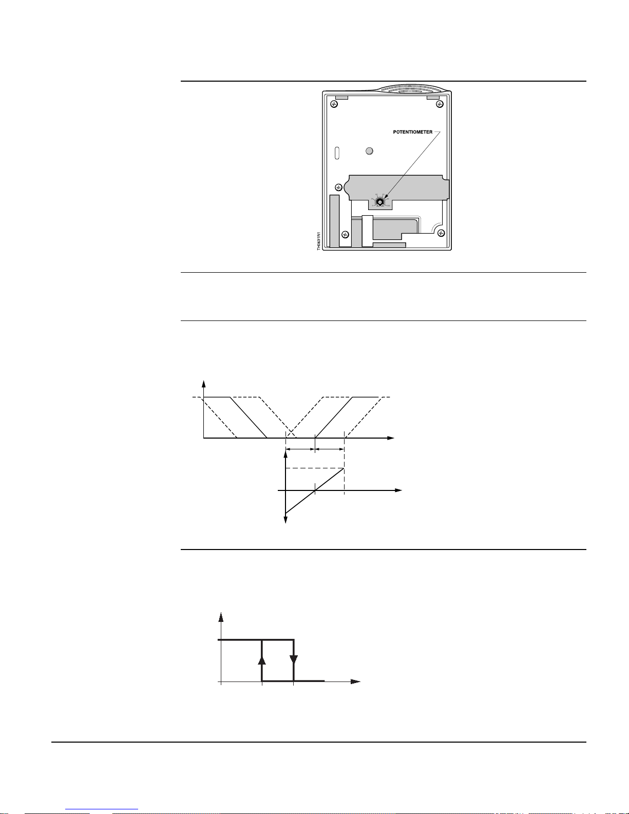
RCU50U
Using the potentiometer located on the circuit board, the cooling signal output can be
limited to a minimum value of between 0 and 100%. This can be used to ensure a
minimum supply air volume. When used in connection with a VAV controller, this
setting must be taken into account. To set minimum limitation, use a screwdriver to
adjust the potentiometer (see Figure 3). Values on the scale are percentage of full
operation.
Page 2
Siemens Building Technologies, Inc.
c/o
Y10 [%]
100
T Room temperature
Y10 Output percentage
W Room temperature set point
XpH Proportional band heating
XpK Proportional band cooling
c/o Changeover
XpH
0
XpK
W
T [˚F]
Page 3
RCU50U and RCU50.2U Room Temperature Controllers Technical Instructions
c
For VAV Systems Document Number 155-327P25
Rev. 1, March, 2002
Minimum Limitation of
Cooling Signal,
Continued
Figure 3. Potentiometer Location (RCU50U).
Inversion of Output
Signal
RCU50.2U
Set Point Shifting
RCU50U
With the RCU50.2U, the output signal can be inverted with the help of DIP Switch
No. 1. If set to ON, 0V corresponds to 0% travel and 10V to 100% travel. In position
OFF, 0V corresponds to 100% travel and 10V to 0% travel.
Signal Input 1 and 2 is used for outside temperature compensation. Using a 0 to 10 Vd
signal, the set point can be shifted by ±22.5°F at 72°F set point. The neutral position is
at 5 Vdc and means no set point shift.
Q(%)
heating cooling
100
W Original set point
W1 Highest set point at 10V input
W2 Lowest set point at 0V input
set point shift
72ºF
0
Set Point Shift (K)
TH0621R1
Figure 4. Set Point Shifting (RCU50U).
Automatic Changeover
RCU50U
The water temperature measured by the changeover sensor (QAH11.1) is used by the
controller to switch from heating to cooling mode, or vice versa. When the water
W2 W1
22.5ºF
0
22.5ºF
1
W
22.5ºF 22.5ºF
5
(72ºF)
10
T [ºF]
Input Voltage (V)
(V) Input voltage
temperature is above 82°F (28°C), the controller switches to heating mode; below
61°F (16°C) it switches to cooling mode.
CM
HM
TH0579R1
Siemens Building Technologies, Inc.
M
61
(16)82(28)
Figure 5. Automatic Changeover Mode.
˚
(˚C)
CM Cooling mode
HM Heating mode
M Operating mode
T
Water temperature
W
T
W
F
Page 3
Page 4
Technical Instructions RCU50U and RCU50.2U Room Temperature Controllers
o
Document Number 155-327P25 for CAV Systems
Rev. 1, March, 2002
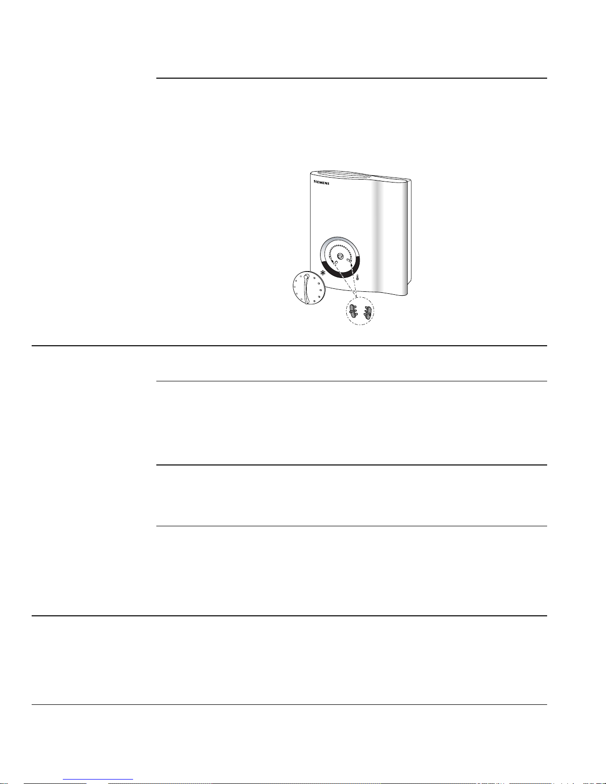
Set Point Limit Stops
The room temperature set point can be limited in increments of 2°F (1°C) by using the
minimum and maximum set point limit stops. This prevents arbitrary set point
readjustments.
To set limit stops, remove the set point knob by pulling it straight off the shaft.
Reposition gray tabs for high and low stops in the holes around the perimeter of knob
as required. See Figure 6.
65
7
0
2
0
60
15
55
10
50
L
a
n
d
i
s
&
75
20
18
22
6
2
5
1
24
14
26
12
1
0
8
S
t
a
e
80
28
30
85ºF
30
Cº
f
a
Operating Modes
Normal Mode
Frost Protection Mode
(RCU50U)
Energy Saving Mode
Operating Mode
Changeover Switch
(RCU50U)
TH0625R1
Figure 6. Set Point Limit Stops.
When dry contact (D1 and Ground) is open, the set point knob setting takes over
control and normal mode is initiated.
Frost protection mode can be initiated by activating the external operating mode
changeover switch, if DIP Switch No. 1 is set to OFF.
If the room temperature falls below 46°F (8°C), the controller will automatically switch t
frost protection mode. In that case, the heating valve opens and the room temperature
is maintained at a set point of 46°F (8°C). The set point adjusted by the user will be
ignored.
Energy saving mode can be initiated by activating the external operating mode
changeover switch, if DIP Switch No. 1 is set to ON.
In energy saving mode, the heating set point is 61°F (16°C) and the cooling set point is
82°F (28°C), independent of the position of the set point knob.
A changeover switch can be connected to status input D1–GND. When the switch
closes its contact (caused by an open window, for instance), the operating mode
changes from normal operation or standby to energy saving mode (if DIP Switch No. 1
is set to ON), or from normal operation or energy saving mode to standby (if DIP Switch
No. 1 is set to OFF).
The operating action of the switch (N.C. or N.O.) can be selected.
Mechanical Design
The unit consists of two parts:
• Plastic housing which accommodates the electronics, the operating elements and
the built-in room temperature sensor.
• Controller base.
The housing snaps into the top and bottom of the mounting base.
Page 4
Siemens Building Technologies, Inc.
Page 5

RCU50U and RCU50.2U Room Temperature Controllers Technical Instructions
r
.
r
For VAV Systems Document Number 155-327P25
Rev. 1, March, 2002
Mechanical Design,
Continued
The screw terminals are mounted on the base. The DIP switches and the potentiomete
are located at the rear of the unit. To access the DIP switches, remove the controller
from the controller base. See Figure 7.
Figure 7. Dip Switch Setting.
Table 3. RCU50U DIP Switches.
DIP Switch No
1 Operating mode changeove
2 Operating action of switch
for external operating mode
Meaning Position ON Position OFF
Changeover between normal
operation, energy saving and
standby
Changeover activated whe n
contact of switch is open
via external switch
changeover
Changeover between
normal operation and energy
saving mode
Changeover activated whe n
contact of switch is closed
(N.O.) 1
(N.C.)
3 Standby OFF Frost protection mode (heating
output ON at a set point of 46°F
4 P-band 2°F (1°C) in heating mode
1°F (0.5 C) in cooling mode
5 Cooling signal output in
Active Inactive1
7°F (4°C) in heating mode1
3.5°F (2°C) in cooling mode
(8°C)1
energy saving mode
Table 4. RCU50.2U DIP Switches.
DIP Switch
No.
Meaning Position ON Position OFF
1 Signal inversion 0 to 10 Vdc Output signal 0 to 10 Vdc1 Output signal 10 to 0 Vdc
1. Factory setting
Accessories
ARG70 Adapter Plate for 2 × 4-inch or 4 × 4-inch conduit boxes
QAH11.1 Changeover/remote sensor
1
1
Notes
• In systems without automatic changeover, the temperature sensor can be replaced
by an external switch for manual changeover.
• In systems with cooling only operation, the controller changeover input (terminals 2
and 3) must be bridged.
• In systems with heating only operation, do not connect sensor to, or bridge
controller changeover input (terminals 2 and 3).
Siemens Building Technologies, Inc.
Page 5
Page 6

Technical Instructions RCU50U and RCU50.2U Room Temperature Controllers
Document Number 155-327P25 for CAV Systems
Rev. 1, March, 2002
Notes, Continued
• Check the settings of DIP Switches No. 1 through No. 5 and of the potentiometer of
the RCU50U, and of DIP Switch No. 1 of the RCU50.2U and change them, if
required
• After applying power, the controller makes a reset, which takes about three
seconds; it is then ready to operate.
• The unit can be located on a wall of the room to be conditioned. Do not mount in
direct sunlight or near other heat or refrigeration sources.
• Mounting height is approximately 60 inches (150 cm) above the floor. (See
Figure 8.)
• The connecting wires can be run to the controller from a recessed conduit box.
• The controller should be opened by authorized personnel only.
Drywall Mounting
Figure 8. Acceptable Mounting Height.
• When mounting the unit, attach the controller base first. Then, make the electrical
connections and fit and secure the cover.
• The controller must be mounted on a flat wall and in compliance with local
regulations.
• Any radiator valves in the room must be set to their fully open positions upon startup.
• User input via set point knob or operating mode/fan speed selector (RCU50.2U
only) results in instantaneous response. There is a one-minute delay before
changes made to temperature sensing and changeover are implemented.
1. Insert a small screwdriver into the bottom of the controller and press in the tab
located in center of the controller.
2. Lift the bottom of the controller from the controller base and push up to remove
cover from two tabs located at the top of the controller base.
3. Separate the controller base from the controller.
Figure 9. Thermostat Cover Separation.
Page 6
Siemens Building Technologies, Inc.
Page 7

RCU50U and RCU50.2U Room Temperature Controllers Technical Instructions
For VAV Systems Document Number 155-327P25
Rev. 1, March, 2002
Drywall Mounting,
4. Using the controller base as a template, mark the hole locations with a pencil.
Continued
5. Drill two 1/4-inch diameter holes for plastic wall anchors.
6. Using a mallet, tap in the pl as tic wa ll anchor s flush wit h wa ll.
7. Pull the wiring through the opening in the upper portion of the controller base.
8. Level mounting plate.
9. Using the two wood screws provided, fasten controller base to wall. Thermostat is
not position sensitive.
10. Pull the wiring through the controller base.
11. Position controller housing over the two mounting lugs located at the top of the
controller base, and press down on cover until bottom lugs snap in place.
12. Terminate wires per wiring instructions located above the terminal block.
Figure 10. Wiring Termination.
13. Reattach the controller to the controller base.
Figure 11. Controller Reattachment.
14. Return selector switches to the normal position (RCU50.2U only). Adjust set point
dial to desired setting.
The installation is now complete.
Siemens Building Technologies, Inc.
Page 7
Page 8

Technical Instructions RCU50U and RCU50.2U Room Temperature Controllers
l
Document Number 155-327P25 for CAV Systems
Rev. 1, March, 2002
4 × 4-inch Electrical Wal
Box Mounting
An ARG70 wall plate adapter is required to mount an RCU50U or RCU50.2U controller
to a 4 × 4-inch electrical wall box. The ARG70 wall plate adapter is included with
electrical wall box mount models.
1. Insert a small screwdriver into the bottom of the controller and press in the tab
located in center of the controller.
2. Lift the bottom of the controller from the controller base and push up to remove
cover from two tabs located at the top of the controller base.
3. Separate the controller base from the controller.
4. Using the four screws provided, fasten wall box adapter (3) to plaster ring (2).
(Plaster ring supplied by others.)
5. Flex adapter mask (4) and snap in place inside wall box adapter (3).
6. Fasten the controller base (5), included with controller, to wall box adapter
assembly (3) and (4) with the two screws provided.
7. Pull wires through plaster ring (2).
TH0567R1
8. Follow Drywall Mounting Steps 6 through 15.
The installation is now complete.
1
2
3
4
5
6
Figure 12. 4 × 4-inch Electrical Wall Box Installation.
1 Electrical wall box
2 Plaster ring
3 Wall box adapter *
* Included with ARG70
Page 8
Siemens Building Technologies, Inc.
4 Adapter mask *
5 Controller base
6 Controller
Page 9

RCU50U and RCU50.2U Room Temperature Controllers Technical Instructions
l
For VAV Systems Document Number 155-327P25
Rev. 1, March, 2002
2 × 4-inch Electrical Wal
Box Mounting
An ARG70 wall plate adapter is required to mount an RCU50U or RCU50.2U controller
to a 2 × 4-inch electrical wall box. The ARG70 wall plate adapter is included with
electrical wall box mount models.
1. Insert a small screwdriver into the bottom of the controller and press in the tab
located in center of the controller.
2. Lift the bottom of the controller from the controller base and push up to remove
cover from two tabs located at the top of the controller base.
3. Separate the controller base (5) from the controller (6).
4. Using the two screws provided, fasten wall box adapter (3) to plaster ring (2).
(Plaster ring supplied by others.)
5. Flex adapter mask (4) and snap in place inside wall box adapter (3).
6. Pull wires through plaster ring (2).
7. Fasten the controller base (5) to wall box adapter assembly (3) and (4) with the two
screws provided.
8. Follow Drywall Mounting Steps 6 through 15.
TH0568R1
The installation is now complete.
1
3
4
5
6
Figure 13. 2 × 4-inch Electrical Wall Box Installation.
1 Electrical wall box
3 Wall box adapter *
4 Adapter mask *
* Included with ARG70
Siemens Building Technologies, Inc.
5 Controller base
6 Controller
Page 9
Page 10

Technical Instructions RCU50U and RCU50.2U Room Temperature Controllers
Document Number 155-327P25 for CAV Systems
Rev. 1, March, 2002
Specifications
Power Supply
Functional Data
Environmental
Conditions
Agency Approvals
General
Operating voltage 24 Vac ±20%
Control action (P) Proportional
Frequency 50/60 Hz
Set point setting range 50°F to 85°F (10°C to 30°C)
P-band in heating mode
RCU50U 2°F or 7°F (1°C or 4°C)
RCU50.2U (fixed) 7°F (4°C)
P-band in cooling mode
RCU50 1°F or 3.5°F (0.5°C or 2°C)
RCU50.2 (fixed) 3.5°F (2°C)
Set point (Energy Saving Mode
Set point (Energy Saving Mode
), heating 61°F (16°C)
), cooling 82°F (28°C)
Set point Frost Protection 46°F (8°C)
Set point shift temperature @ 72°F (22°C) ±22.5°F (±40°C)
Control outputs, terminals 4 and 5
Vol tag e 0 to 10 Vdc
Current ±1 mA
Status input D1 (RCU50U)
Contact sensing 6 to 15 Vdc/3 to 6 mA
Insulation against live voltage 4 kV
Maximum number of contacts connected 50
in a panel
Status inputs 1 and 2 (RCU50U)
Set point shift of ± 22.5°F @ 72°F (22°C) 0 to 10 Vdc
Neutral position (no set point shift) 5 Vdc
Signal input terminals 2 and 3 for changeover QAH11.1 safety class 2
sensor
NTC resistor 3K Ω @ 77°F (25°C)
Maximum copper cable length 16 AWG
For Input Signal terminals 1 & 2 (RCU50U) 262 feet (80m)
For Input Signal D1 (RCU50U) 262 feet (80m)
Operation
Temperature 32°F to 122°F (0°C to 50°C)
Humidity <95% rh
Shipping and storage
Temperature –13°F to 158°F (–25°C to 70°C)
Humidity <95% rh
UL listed UL 873
Conforms to CE requirements
cUL certified to Canadian Standard
C22.2 No. 24-93
Connection terminals Use solid wires or prepared stranded
wires. 2 × 16 AWG or 1 × 14 AWG
Maximum 20 AWG
Weight
RCU50U 0.5 lb (0.23 kg)
RCU50.2U 0.5 lb (0.23 kg)
Housing color
Cover White
Base Gray
Page 10
Siemens Building Technologies, Inc.
Page 11

RCU50U and RCU50.2U Room Temperature Controllers Technical Instructions
.
t
For VAV Systems Document Number 155-327P25
Rev. 1, March, 2002
Wiring Diagrams
G
G
Dimensions
G0
TH0637R1
AC
24 V
7
6
54
1mA
max.
7 D1 GND
123
24 VAC
645
G0
TH0638R1
1mA
max.
Figure 14. RCU50U Wiring Diagram. Figure 15. RCU50.2U Wiring Diagram.
1 Signal input set point shift
2 Measuring neutral
3 Heat/cool "changeover sensor" inpu
4 0 to 10 Vdc control signal
5 Ground for control signal
6 Operating voltage, 24 Vac negati ve
7 Operating voltage, 24 Vac positive
D1 Signal input for potential-free
operating mode changeover switch
G 24 Vac, digital input
G0 24 Vac
GND Ground
0.16 (4)
4.49
(114.15)
1.38
(35)
1.10
(28)
1.10
(28)
1.10
(28)
0.16
(4)
1.10
1.18
(28)
(30)
TH0575R1
Figure 16. Controller and Baseplate Dimensions in Inches (Millimeters).
3.80
(96.6)
1.69
(42.8)
0.46
(11.8)
TH0576R1
1.02
(26)
3.34
(90)
0.16 (4)
1.18
(30)
4.09
(104)
Information in this publication is based on current specifications. The company reserves the right to make c hanges i n specifications and models as
design improvements are introduced. Other product or company names mentioned herein may be the trademarks of their respecti ve owners.
© 2002 Siemens Building Technologies, Inc.
Siemens Building Technologies, Inc.
1000 Deerfield Parkway
Buffalo Grove, IL 60089-4513
U.S.A.
Your feedback is important to us. If you have
comments about this document, please send
them to technical.editor@sbt.siemens.com
Document No. 155-327P25
Printed in the U.S.A
Page 11
 Loading...