

Page 1
s
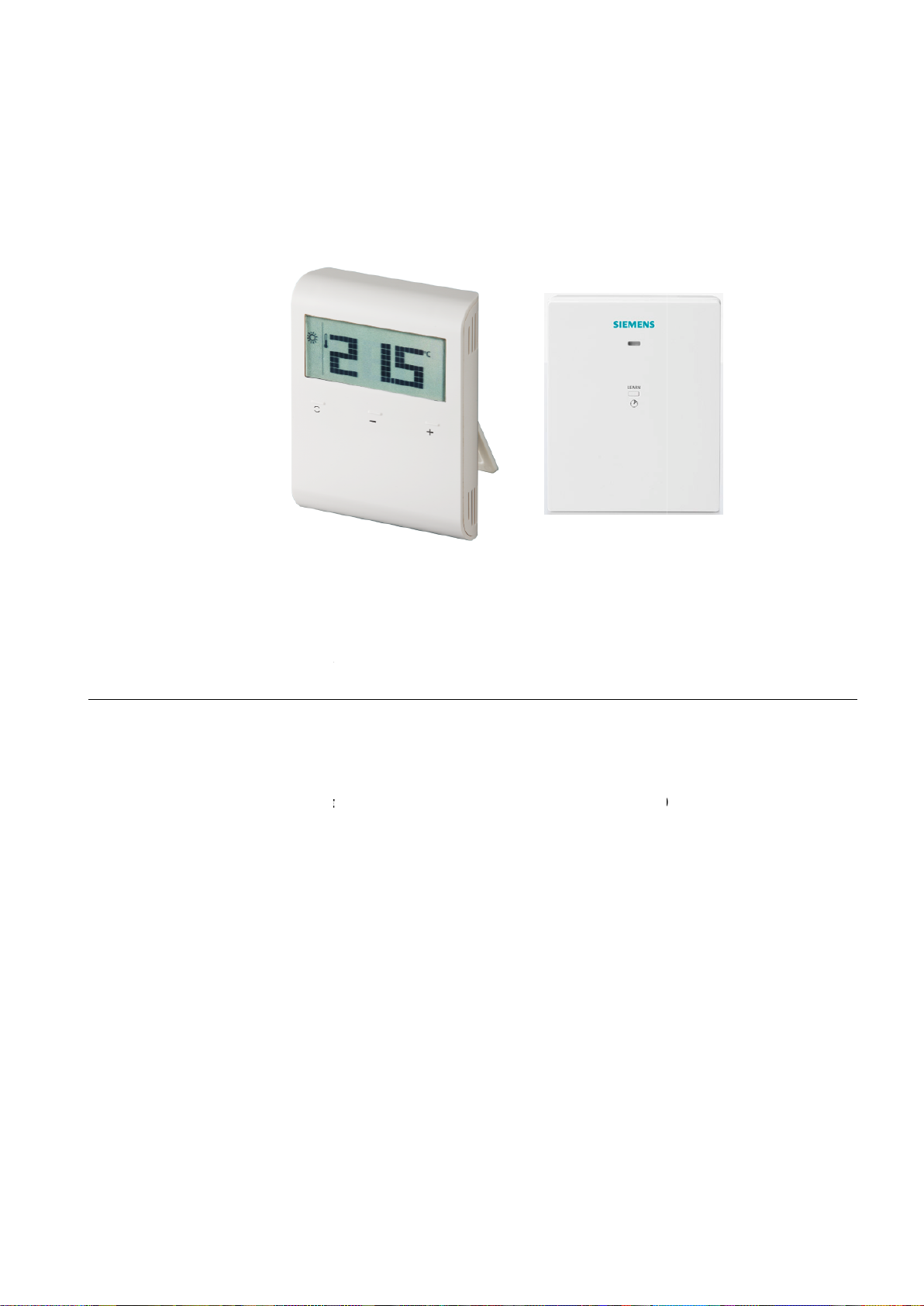
RDD100.1RF
Wireless room
thermostat with LCD
f
or heating systems
oom temperature control
Comfort,
position control with O
Adjustable commissioning and control parameters
attery
ains
Building Technologies
RDD100.1RFS
(RDD100.1RF)
1
42
4
∂ R
∂
∂ 2-
∂
∂ B
∂ M
RCR100RF
Economy and Protection mode
n/Off control output
-powered room thermostat DC 3 V
-powered receiver AC 230 V (RCR100RF)
CB1N1424en
2017-11-21
Page 2
Use
Q14
Functions
The RDD100.1RFS is used to control the room temperature in heating systems.
Typical applications:
∂ Apartments
∂ Commercial spaces
∂ Schools
For the control of the following pieces of equipment:
∂ Thermal valves or zone valves
∂ Gas or oil boilers
∂ Fans
∂ Pumps
∂ Room temperature control via built-in temperature sensor
∂ Selection of operating mode with touchkey
∂ Display of current room temperature or setpoint in ↓C or ↓F
∂ Touchkey lock (manually)
∂ Setpoint lock
∂ Reloading factory settings for commissioning and control parameters
∂ Standalone wireless transmitter and receiver
∂ Wireless operating frequency 433 MHz
Temperature control
Type summary
Ordering
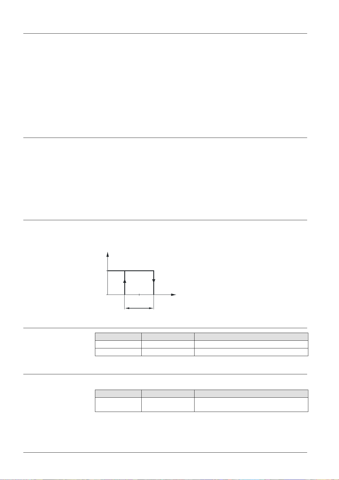
The RDD100.1RFS acquires the room temperature with its built-in sensor and
maintains the setpoint by delivering control commands. The switching differential is
1 K.
1424D01
ON
T Room temperature
SD Switching differential
W Room temperature setpoint
Q14 Output signal for heating
OFF
W
SD
T[°C]
Product No. Stock No. Features
RDD100.1RF
RCR100RF
S55770-T319
S55770-T286
Battery-powered room thermostat DC 3 V
Receiver AC 230 V
When ordering, please indicate product No. / stock No. and description.
Product No. Stock No. Description
RDD100.1RFS
S55770-T281
Set consisting of room thermostat and
receiver
Valve actuators must be ordered separately.
2 / 13
Siemens RDD100.1RFS Wireless room thermostat with LCD CB1N1424en
Building Technologies 2017-11-21
Page 3
RDD100.1RFS
Equipment combinations
room thermostat consists of
Plastic housing which accommodates the electronics, the operating
and the room temperature sensor
Mounting plate
Table stand
The housing engages in the mounting plate and
The optional table stand snap
The RCR100RF receiver consists of
Plastic housing which accommodates the electronics
Mounting plate
RDD100.1RF
Description
Electromotoric actuator
Electrothermal actuator
(for radiator valve
Electrothermal actuator
(for small valve
Damper
Damper actuator
Damper
Rotary damper actuator
is secured with a
the mounting plate.
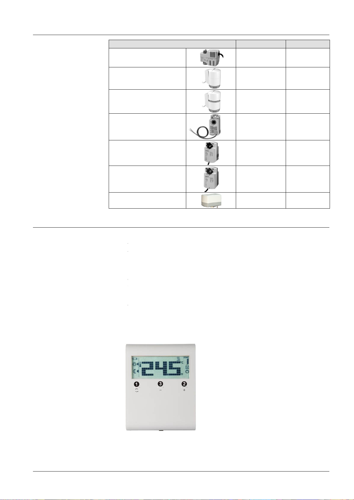
Touchkey for o
for increasing a value
for decreasing a value
Product No.
SFA21..
STA23..
STP23..
GDB..
GSD..
GQD..
GXD..
Data Sheet
Mechanical design
s 2.5 mm)
actuators
actuators
s
s
s)
s
4863
4884
4884
4634
s
4603
4604
s
4622
Operation and settings
The
∂
∂
∂
∂
∂
3 parts:
with screw terminals
s onto the rear of
with screw terminals
2 parts:
1)
2) Touchkey
elements
screw.
perating mode
Siemens
Building Technologies
Wireless room thermostat with LCD
3) Touchkey
3 / 13
CB1N1424en
2017-11-21
Page 4
RCR100RF
C
F
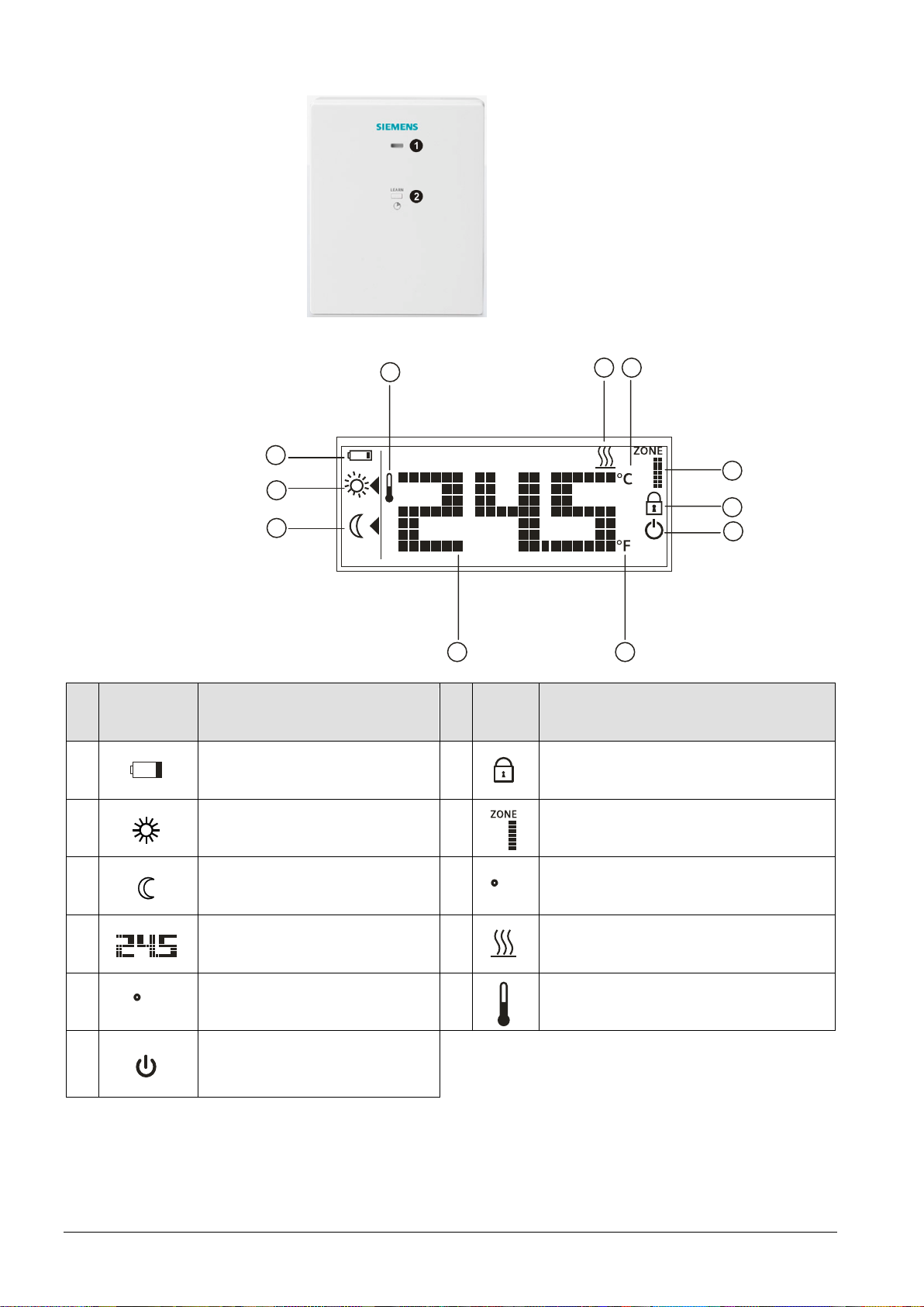
1) LED for indication of operating state
2) LEARN button (or override)
Display
11
1
2
3
109
# Symbol Description # Symbol Description
1
Indicating that batteries need to
be replaced
7
Touchkey lock activated
8
7
6
54
2 Comfort mode
3 Economy mode
4
5
Display of room temperature,
setpoint, etc.
Room temperature in degrees
Fahrenheit
8
9
10
Display of zone (default is 1)
Room temperature in degrees Celsius
Heating On
11 Current room temperature
Protection mode (Protection
6
mode icon can be enabled via
parameter settings)
4 / 13
Siemens RDD100.1RFS Wireless room thermostat with LCD CB1N1424en
Building Technologies 2017-11-21
Page 5

RDD100.1RFS
Mounting and installation notes
Do not mount the thermostat in niches or bookshelves, not behind curtains, not
above or near heat sources, and not exposed to direct solar radiation. Mount
about 1.5 m above the floor.
Mount the
from heating/cooling
Install the receiver close to the controlled un
Choose the location to ensure largely interference
mounting the
Do not mount in a control panel
Do,Do not mount near electrical cables and equipment
microwaves, etc.
Do not mount near larger metallic structures or constructional elements with
fine metal meshes such as special glass or special concrete
See Mounting I
Ensure that wiring,
Correctly
Use only valve
If the thermostat cannot accommodate all cables, power must be fed to the
system via an e
Warning!
No internal line protection for supply lines to external consumers.
Risk of fire and injury
Adapt the line diameters as per local regulations to the rated value of the
installed overcurrent protection device.
The AC 230
current of no more than 10 A
Disconnect from
Make sure the receiver is not c
thermostat in a clean and dry location
and not exposed to drip or splash water
it if possible
free reception.
enclosed with the thermostat.
and earthing comply with local regulations
thermostat and the valve actuators
circuit breaker with a rat
the unit from its mounting plate
onnected to power during
it
Mounting
Wiring
∂
room
without direct air flow
equipment,
∂
∂
-
When
receiver, observe the following:
,
,
not mount on metallic surfaces
such as PCs, TVs,
,
nstructions CB1M1439xx
∂
∂
size the cables to the
∂
protection
actuators rated for AC 24… 230 V
∂
xternal terminal block
due to short-circuits!
∂
∂
∂
V mains supply line must have a
power supply before removing
∂
Siemens
Building Technologies
Wireless room thermostat with LCD
ed
wiring
5 / 13
CB1N1424en
2017-11-21
Page 6

Commissioning notes
Commissioning
Sensor calibration
Setpoint and setpoint
lock
Touchpad scanning
rate
After power is applied, the thermostat carries out a reset during which all LCD
segments flash, indicating that the reset is correctly made. After the reset, the
thermostat is ready for commissioning by qualified HVAC personnel.
The control parameters of the thermostat can be set to ensure optimum
performance of the entire system (refer to Operating Instructions CB1B1424en,
section "Do you want to change parameters?").
If the temperature shown on the display does not agree with the room temperature
effectively measured, the temperature sensor can be recalibrated. For that
purpose, adjust parameter P04.
We recommend to review the setpoint setting range and setpoint lock (for public
spaces) using parameters P05…P08 and change them as needed to achieve
maximum comfort and energy savings.
Since the thermostat uses touch technology and to minimize battery power
consumption, a parameter P21 (adjustable from 0.25 to 1.5 seconds) is
implemented for the user to adjust.
This means that when, for a certain time, the user does not touch the touchpad, the
unit operates in power saving mode and the touchpad is running at a scanning rate
of 1 second.
(From the calculation – assuming 4 operations per day on the thermostat, the
estimated 1-second scanning rate results in a battery life of 1 year. If the user
increases the scanning rate, the batteries’ life is extended.)
Change of batteries
LED indication on
RCR100RF
If the battery symbol appears, the batteries are almost exhausted and should
be replaced. Use alkaline batteries type AAA.
For the pairing process between transmitter and receiver, refer to Operating
Instructions CB1B1424en, section "Do you want to pair transmitter and receiver?".
The table below describes the behavior of the RCR100RF:
State of receiver State of LED
Power up (or reset) The red and green LEDs flash alternately for 5
seconds and then change to constantly red.
Note: If the receiver was programmed before, it
will immediately change to constantly red.
Learning mode
Successful learning mode
The red and green LEDs flash alternately.
If learning was successful, the green LED will
flash for 10 minutes.
Signal ok and output status
change
The green LED is lit. If the output state changes,
the green LED flashes for 3 seconds and then
changes back to constantly green.
Fails to receive wireless data If the RCR100RF fails to receive wireless data,
the red LED will start to flash after 125 minutes.
If the RCR100RF signal is recovered, it will
resume the previous LED state.
Override via the
RCR100RF
6 / 13
Siemens RDD100.1RFS Wireless room thermostat with LCD CB1N1424en
Building Technologies 2017-11-21
Page 7

Operating notes
The receiver provides an override function (boiler test, emergency operation). It
allows the installer to override the relay to be permanently energized, regardless of
the wireless data received.
To activate the override function, press and hold the button for at least 10
seconds and release. The LED is constantly green and off once every 5 seconds,
indicating that the override function is enabled.
To disable the override function, press the button once.
The RDD100.1RF provides Comfort, Economy and Protection mode. The
difference between Comfort and Economy mode is only the room temperature
setpoint. The changeover between Comfort, Economy and Protection mode is
made by pressing touchkey .
Comfort mode
Economy mode
Protection mode
Maintenance notes
Disposal
When Comfort mode is activated, symbol appears on the display. The setpoint
(20 ºC) can be readjusted by pressing touchkeys + and –.
When Economy mode is activated, symbol appears on the display. The setpoint
(16 ºC) can be readjusted by pressing touchkeys + and –.
If the temperature falls below 5 ºC, the thermostat automatically activates the
heating output. Symbol appears only if the icon is enabled via parameter
settings.
Thermostat and receiver are maintenance-free.
The device is considered an electronic device for disposal in terms of the
European Directive 2012/19/EU and may not be disposed of as domestic
garbage.
∂ Dispose of the device through channels provided for this purpose.
∂ Comply with all local and currently applicable laws and regulations.
∂ Dispose of empty batteries in designated collection points.
7 / 13
Siemens RDD100.1RFS Wireless room thermostat with LCD CB1N1424en
Building Technologies 2017-11-21
Page 8

WARNING
●
Do not heat the batteries to more than 85
°C
.
water. Consult a doctor.
Risk of explosion due to fire or short-circuit, even if the batteries are empty
Risk of injuries from by flying parts
● Do not allow the batteries to come into contact with water.
● Do not charge the batteries.
● Do not damage or destroy the batteries.
WARNING
Electrolyte leakage
Chemical burns
● Only grasp damaged batteries using suitable protective gloves.
● If electrolyte comes into contact with eyes, immediately rinse eyes with plenty of
Observe the following:
∂ Only replace batteries with batteries of the same type and from the same manufacturer.
∂ Observe the polarities (+/-).
∂ The batteries must be new and free from damage.
∂ Do not mixed new batteries with used batteries.
∂ Store, transport, and dispose of the batteries in accordance with local regulations, guidelines, and laws.
Also observe information from the battery manufacturer.
8 / 13
Siemens RDD100.1RFS Wireless room thermostat with LCD CB1N1424en
Building Technologies 2017-11-21
Page 9

Technical data of RDD100.1RF
*)
RCM
*)
Class I
General
Operating voltage DC 3 V (2 x 1.5 V alkaline batteries AAA)
Power supply
For battery life (RDD100.1RF), see below (alkaline batteries type AAA).
Battery life calculation is based on the touchpad scanning rate during idle time
(assuming a user presses 4 touchkeys per day):
Scanning rate 0.25 s
Scanning rate 0.5 s
Scanning rate 1 s (default)
Scanning rate 1.5 s
Function data
Switching differential SD
Comfort mode
Economy mode
Built-in room temperature sensor
Setpoint setting range
Accuracy at 25 °C
Temperature calibration range
Resolution of settings and displays
Setpoints
Temperature value displays
Environmental conditions
Operation
Climatic conditions
Temperature
Humidity
Transport
Climatic conditions
Temperature
Humidity
Mechanical conditions
Storage
Climatic conditions
Temperature
Humidity
Standards and directives
EU Conformity (CE)
311 days battery life
322 days battery life
357 days battery life
377 days battery life
1 K
20 °C (5...35 °C)
16 °C (5...35 °C)
5…35 °C (Comfort/Economy mode)
<±0.5 K
±3.0 K
0.5 °C
0.5 °C
As per IEC 60721-3-3
Class 3K5
0…50 °C
<95% r.h.
As per IEC 60721-3-2
Class 2K3
-25…60 °C
<95% r.h.
Class 2M2
As per IEC 60721-3-1
Class 1K3
-25…60 °C
<95% r.h.
CE1T1420xx
conformity
CE1T1420en_C1
Safety class II as per EN 60730-1, EN 60730-2-9
Pollution class II as per EN 60730-1
Degree of protection of housing IP30 as per EN 60529
Environmental
compatibility
The product environmental declaration CE1E1420xx*) contains data on
environmentally compatible product design and assessments (RoHS compliance,
materials composition, packaging, environmental benefit, disposal).
Eco design and
labelling directives
Based on EU Regulation 813/2013 (Eco design directive) and 811/2013 (Labelling
directive) concerning space heaters, combination heaters, the following classes
apply:
- Application with On/Off
value 1%
operation of a heater
Connection terminals for Solid wires or prepared stranded wires
2 x 1.5 mm2 or 1 x 2.5 mm2 (Min. 0.5 mm2)
Weight 0.152 kg
Color of housing front RAL9003
*) The documents can be downloaded from http://siemens.com/bt/download.
9 / 13
Siemens RDD100.1RFS Wireless room thermostat with LCD CB1N1424en
Building Technologies 2017-11-21
Page 10

RDD100.1RFS
Technical data of RCR100RF
Frequency
Switching capacity of relays
Switching voltage
Switching
At AC 230 V
No internal fuse.
External preliminary protection with max. C 10 A circuit breaker in the supply lines
required under all circumstances.
External protection for incoming
Circuit breaker
Circuit breaker tripping characteristic
Contact life at AC 230 V
A res.
Insulating strength
Between relay contacts and coil
Between relay contacts (same pole)
Connection terminals
For solid wires
For stranded wires
Climatic conditions
Temperature
Humidity
Climatic conditions
Temperature
Humidity
Mechanical conditions
Climatic conditions
Temperature
Humidity
EU Conformity (CE)
conformity to
EMC emission standard
Safety class
Pollution class
Degree of protection of housing
The product environmental declaration CE1E1420xx
environmentally compatible product design and assessments (RoHS compliance,
materials composition, packaging, environmental benefit, disposal).
r of housing front
Color of housing front
*) The documents can be downloaded from
-
Max. 8 A res., 2 A ind.
Type B, C or D to EN 60898
in.
IEC 60721
IEC 60721
IEC 60721
*)
4251.1:1999
II as per EN 60730
II as per EN 60730
EN 60529
*)
contains data on
http://siemens.com/bt/download
Power supply
Switching outputs
(Q11, Q12, Q14)
Electrical connections
Environmental
conditions
Standards and directives
Operating
Power
Voltage
Current
At 8
Operation
Transport
Storage
voltage
current
cable
AC 230 V +10%/
<10 VA
48...63 Hz
AC 24...230 V
8(2) A
Max. AC 230 V
Min. AC 24 V
Min. 200 mA
Max. 10 A
60947
Guide value:
1 x 10⁵ cycles
AC 5,000 V
AC 1,000 V
Screw terminals
2 x 1.5 mm
2
1 x 2.5 mm2 (M
As per
Class 3K5
0…50 °C
<95% r.h.
As per
Class 2K3
-25…60 °C
<95% r.h.
Class 2M2
As per
Class 1K3
-25…60 °C
<95% r.h.
CE1T1420xx
15%
and EN
0.5 mm2)
-3-3
-3-2
-3-1
Environmental
compatibility
Colo
General
10 / 13
Siemens
Building Technologies
Weight
Wireless room thermostat with LCD
AS/NZS
-1, EN 60730-2-9
IP30 as per
RAL9003
0.152 kg
RAL9003
.
CB1N1424en
2017-11-21
Page 11

Connection diagrams
Lx
L
1
424S0
1
1424S02
1424S
0
3
Application examples
10 A 10 A
L
T
N1
LL
N
AC 230 V
L – N AC 230 V/Lx – Nx AC 24…230 V
Q12
Y1
Q11
Q14
N2
8 (2) A
Max.
L Live, AC 230 V
Q11 Live, AC 24…230 V
Q14 NO contact, AC
24…230 V/8(2) A
Q12 NC contact, AC
AC 24...230 V
24…230 V/8(2) A
N Neutral conductor
Nx Neutral conductor
N1 Transmitter
1424A0 1
RDD100.1RF
N2 Receiver RCR100RF
Y1 Actuating device
T
N1
Y2
T
F1
T
F2
N2
M1
Wireless room thermostat with receiver,
control of a gas-fired wall-hung boiler
N1
T
N2
Y1
M1
T
Y2
T T
N2
F1F2
N1
M1
Wireless room thermostat with receiver,
control of a gas-fired floor-standing
boiler
F1 Thermal reset limit thermostat
F2 Safety limit thermostat
M1 Circulating pump
N1 RDD100.1RF room thermostat
N2 RCR100RF receiver
Y1 3-port valve with manual
adjustment
Y2 Magnetic valve
Wireless room thermostat with receiver,
control of a heating circuit pump
(precontrol by manual mixing valve)
11 / 13
Siemens RDD100.1RFS Wireless room thermostat with LCD CB1N1424en
Building Technologies 2017-11-21
Page 12

Dimensions
106
21.5
Ø60
27.5
84
103
2-Ø5.5
Dimensions in mm
Room thermostat RDD100.1RF
85
Receiver RCR100RF
0.5
25.5
0.5
4.1
7.1
Ø80
83.5
82.93
39.8
1424M01
4.1
7.1
Ø80
Ø60
83.5
1424M02
12 / 13
Siemens RDD100.1RFS Wireless room thermostat with LCD CB1N1424en
Building Technologies 2017-11-21
Page 13

Issued by
www.siemens.com/buildingtechnologies
Siemens Switzerland Ltd.
Building Technologies Division
International Headquarters
Gubelstrasse 22
CH-6300 Zug
Tel. +41 58-724 24 24
Siemens RDD100.1RFS Wireless room thermostat with LCD CB1N1424en
Building Technologies 2017-11-21
Technical specifications and availability subject to change without notice.
© Siemens Switzerland Ltd, 2013 - 2017
13 / 13
 Loading...