

Page 1

Installation Instructions
Model RCM-1
Riser Control Module
Fire Safety
Siemens Building Technologies, Inc.
8 Fernwood Road
Florham Park, New Jersey 07932
P/N 315-093878-11
Siemens Building Technologies, Ltd.
2 Kenview Boulevard
Brampton, Ontario L6T 5E4 CN
Page 2

Table of Contents
INTRODUCTION................................................................................................... 3
Electrical Ratings ............................................................................................ 3
Modes of Operation ........................................................................................ 3
Diagnostic LEDs ............................................................................................. 3
RCM-1 Diagnostic LEDs - Table 1 .................................................................. 4
DESCRIPTION OF THE RCM-1 TERMINALS ..................................................... 5
RCM-1 APPLICATIONS - Table 2 ....................................................................... 5
Application 1 - Typical Style 4 Installation ....................................................... 6
Application 2 - Style 4 with a Style 4 Output Only Extension ......................... 6
Application 3 - Typical Style 7 Installation ....................................................... 6
Application 4 - Style 7 with a PORT C Extension ........................................... 7
Application 5 - Style 4 Fiber Optic Installation ................................................ 7
Application 6 - Style 4 Fiber Optic with a PORT C Fiber Optic Extension...... 8
Application 7 - Style 7 Fiber Optic with a PORT C Fiber Optic Extension...... 8
Application 8 - Combination Wire and Fiber Installation................................. 9
Application 9 - Style 4 Repeater Installation ................................................... 9
INSTALLATION .................................................................................................... 9
Network Address Programming (S1) - Table 3 ............................................. 10
S2 Settings - Table 4..................................................................................... 11
Application 1 - Typical Style 4 Connections .................................................. 12
Application 2 - Typical Style 4 Connections with PORT C Extension ........... 13
Application 3 - Typical Style 7 Connections .................................................. 14
Application 4 - Style 7 Connections with PORT C Extension ....................... 15
Applications 5 and 6 - Typical Style 4 Fiber Optic Connections with Optional
PORT C Extension ........................................................................................ 16
Application 7 - Typical Style 7 Fiber Optic Connections with Optional
PORT C Extension ........................................................................................ 17
Application 8 - Combination Fiber and Wire Style 4 Connection.................. 18
Application 9 - Style 4 Repeater Connection ................................................ 19
WIRING CONFIGURATIONS FOR THE OCC AND ACM ................................. 20
2
Page 3
INTRODUCTION
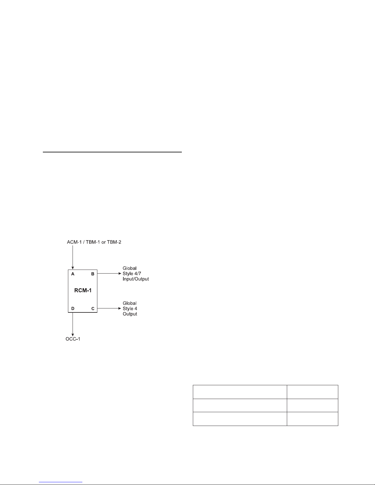
The Model RCM-1 Riser Control module from
Siemens Building Technologies, Inc.provides
control and supervision of global paging risers
in MXL voice networks. The RCM-1 is a doublewidth card and has 4 ports (See Figure 1) with
the following inputs and outputs:
PORT STYLE FUNCTION
A
B
C
D
6 Audio signal input
4/7 Audio signal input/output
4 Audio signal output
6 Audio signal output
The RCM-1 supervises Port B for open and
short circuits, reports by exception to the MXL,
and isolates the fault.
must be used for transient protection (UL 1459).
Refer to LLM-1 Installation Instructions, P/N 315-
093530.
Modes of Operation
The RCM-1 can operate in the following modes:
Local Mode The audio from the local MXL
(ACM) will be switched to local
speaker zones (OCCs). The
A D and B C
Global Mode 1 The audio output from the local
C and D
B
Global Mode 2 The audio from the local
A B, C and D
For additional information on the MXL/MXLV
System, refer to the MXL/MXLV Manual, P/N
315-092036.
global audio riser will be
switched to Port C, the Style 4
output riser.
MXL is disconnected. The
audio from the global riser is
connected to the local speaker
zones and to Port C, the Style
4 output riser.
system is connected to both
the local speaker outputs and
the global risers.
Figure 1
RCM-1 Ports
Only one RCM-1 may be connected to the
MXL. The module communicates with the MXL
using the RS-485 MNET. If the RCM-1 detects
that supervision is lost with the MXL, it will
automatically switch to Local Mode.
If any copper wire pair leaves the building
(Campus Configuration) the LLM-1 module
Diagnostic LEDs
The RCM-1 has two yellow diagnostic LEDs and
six green diagnostic LEDs along its top edge.
Their functions are described in Table 1 (Refer to
Figure 2 for their location).
ELECTRICAL RATINGS
tnerruCeludoMCDV5evitcAAm08
tnerruCeludoMCDV42evitcAAm081
tnerruCeludoMCDV42ybdnatSAm002
3
Page 4
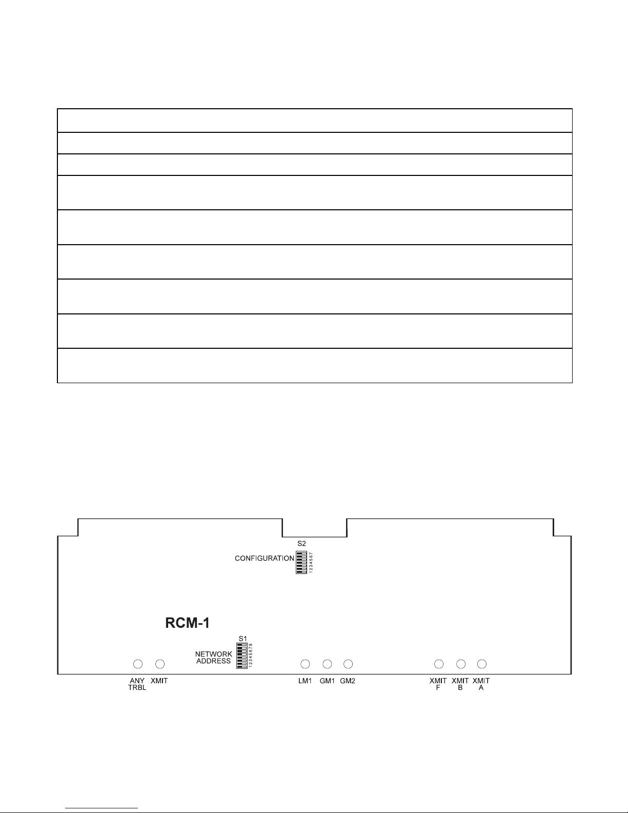
TABLE 1
RCM-1 DIAGNOSTIC LEDS
LED COLOR FUNCTION
Any Trouble
XMIT Enable
XMIT A
XMIT B
XMIT F
LM1
GM1
GM2
Yellow Lights when the RCM-1 cannot communicate with the MXL.
Yellow Lights whenever the RCM-1 transmits a message to the MXL.
Green Lights when the RCM-1 transmits voice using the copper
wire RECV connections.
Green Lights when the RCM-1 transmits voice using the copper
wire XMIT connections.
Green Lights when the RCM-1 transmits voice using any of the fiber
optic ports.
Green Lights when the RCM-1 is in local mode.
Flashes when there is no valid carrier on the riser.
Green Lights when the RCM-1 is in global mode 1.
Flashes when there is no valid carrier on the riser.
Green Lights when the RCM-1 is in global mode 2.
Flashes when there is no valid carrier on the riser.
Figure 2
RCM-1 Module Board
4
Page 5
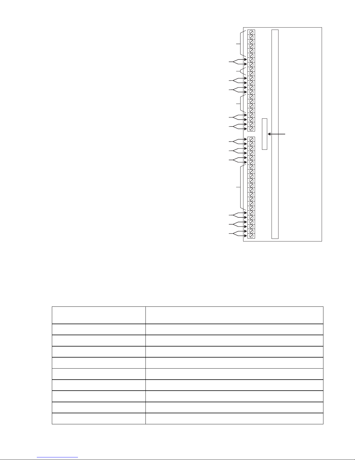
Note:
Polarity must be observed
with all riser connections.
Odd pins are hi side while
even pins are lo side. See
the separate wiring
connections for the ACM/
TBM and the OCC shown
in Figure 12.
NOT USED
PORT C: Copper Interface, Transmit, Style 4 (CT4)
NOT USED
PORT B: Copper Interface, Receive, Style 4 (BR4)
PORT B: Copper Interface, Transmit, Style 4 (BT4)
NOT USED
PORT B: Copper Interface, Receive, Style 7 (BR7)
PORT B: Copper Interface, Transmit, Style 7 (BT7)
PORT B: Fiber Interface, Style 4 (BF4)
PORT B: Fiber Interface, Style 7 (BF7)
PORT C: Fiber Interface, Style 4 (CF4)
NOT USED
PORT D: Copper Connection To The OCC
PORT D: Copper Connection To The OCC
PORT A: Copper Connection To The ACM
1
2
3
4
5
6
7
8
9
10
11
12
13
14
15
16
17
18
19
20
21
22
1
2
3
4
5
6
7
8
9
10
11
12
13
14
15
16
17
18
19
20
21
22
RCM-1
CABLE TO
MMB OR PSR
P/N 555-190967
OMM-1
OMM-2
or
Figure 3
Description of the RCM-1 Terminals
The RCM-1 can be connected in many different ways. Table 2 describes the various applications. The
block diagrams below show the possible configurations.
TABLE 2
RCM-1 APPLICATIONS
Application No.
(See Corresponding Diagram)
1 Typical Style 4 installation
2 Style 4 installation with a Style 4 output only extension
3 Typical Style 7 installation
4 Style 7 installation with a Style 4 extension
5 Style 4 installation with fiber optic transmission
6 Style 4 fiber optic with a Style 4 fiber optic output only extension
7 Style 7 fiber connections with a Style 4 output only fiber extension
8 Combination wire and fiber installation
Configuration
9 Style 4 Repeater Installation
5
Page 6
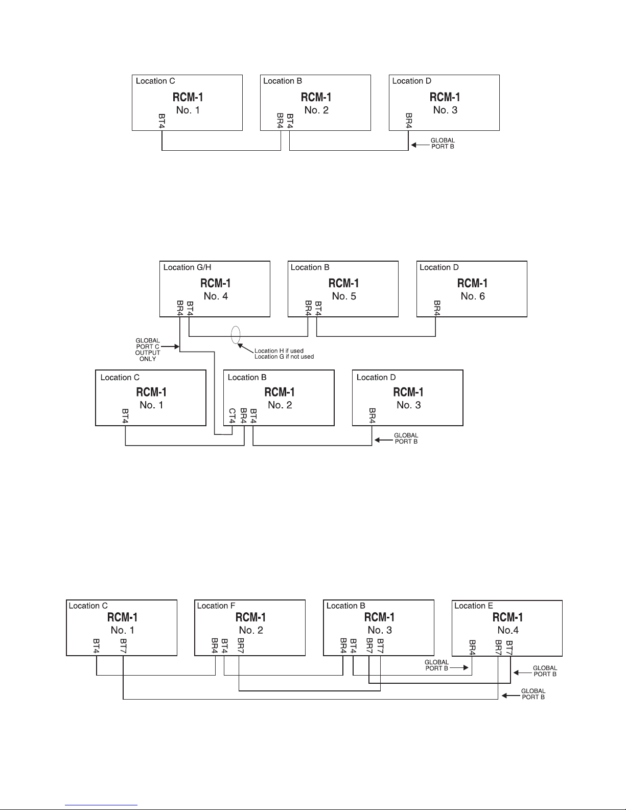
Application 1
Typical Style 4 Installation
RCM-1 Nos. 4, 5, and 6 have local ACMs, but cannot
output to the global bus — they can only receive.
Application 2
Style 4 with a Style 4 Output Only Extension
Application 3
Typical Style 7 Installation
6
Page 7

Application 4
Style 7 with a PORT C Extension
Application 5
Style 4 Fiber Optic Installation
7
Page 8

Application 6
Style 4 Fiber Optic with a PORT C Fiber Optic Extension
Style 7 Fiber Optic with a PORT C Fiber Optic Extension
Application 7
8
Page 9

Application 8
Combination Wire and Fiber Installation
Application 9
Style 4 Repeater Installation
INSTALLATION
Remove all system power before
installation, first battery and then AC.
(To power up, connect the
AC first, then the battery.)
The RCM-1 has two configuration dipswitches,
S1 and S2. Set the dipswitches before install-
ing the RCM-1 into the OMM-1/2. (See NOTE
following Table 4 for the operation of
dipswitches.)
The RCM-1 takes up one of the 255 possible
network addresses. Use switch S1 to set the
MXL network address. Set this switch according
to the address where the RCM-1 is installed in
the MXL’s network map. Refer to the AccuLINK
(CSG-M) configuration printout for the address of
the module. See Table 3 for settings.
In addition to S1 which is used to set the network
address, the RCM-1 has a second bank of
dipswitches, S2, which must be correctly configured for the RCM-1 to operate properly. Refer to
Table 4 for a description of the functions for each
of the switches in S2.
9
Page 10

TABLE 3
NETWORK ADDRESS PROGRAMMING (S1)
RDDA12345678RDDA12345678RDDA12345678RDDA12345678
000
100
200
300
400
500
600
700
800
900
010
110
210
310
410
510
610
710
810
910
020
120
220
320
420
520
620
720
820
920
030
130
230
330
430
530
630
730
830
930
040
140
240
340
440
540
640
740
840
940
050
150
250
0
35
450
550
650
750
850
950
060
160
260
360
LAGELLI
LAGELLI
LAGELLI
XXOOOOOO
OOXOOOOO
XOXOOOOO
OXXOOOOO
XXXOOOOO
OOOXOOOO
X
OOXOOOO
OXOXOOOO
XXOXOOOO
OOXXOOOO
XOXXOOOO
OXXXOOOO
XXXXOOOO
OOOOXOOO
XOOOXOOO
OXOOXOOO
XXOOXOOO
OO
XOO
OOXOXOOO
XOXOXO
OXXOXOOO
XXXOXOOO
OOOXXOOO
XOOXXOOO
OXOXXOOO
XXOXXOOO
OOXXXOOO
XOXXXOOO
OXXXXOOO
XXXXXOOO
OOOOOXOO
XOOOOXOO
OOXOO
OXO
XXOOOXOO
OOXOOXOO
XOXOOXOO
OXXOOXOO
XXXOOXOO
OOOXOXOO
XOOXOXOO
OXOXOXOO
XXOXOXOO
OOXXOXOO
XOXXOXOO
OXXXOXOO
XXXXOXOO
OOOOXXOO
XOOOXXOO
OXOOXXOO
XXOOXXOO
OOXOXXOO
XOXOXXOO
OXXOXXOO
XXXOXXOO
OOOXXXOO
XOOXXXOO
OXOXXXOO
XXOXX
OOXXXXOO
XOXXXXOO
OXXXXXOO
XXXXXXOO
460
560
660
760
860
960
070
170
270
370
470
570
670
770
870
970
080
180
280
380
480
580
680
780
880
980
090
190
290
390
490
590
690
790
890
990
001
101
201
301
401
501
601
701
801
901
011
111
211
311
411
511
611
711
811
1
91
021
121
221
321
421
521
621
721
XO
)NOro(DESOLC=X)FFOro(NEPO=O
OOOOOOXO
XOOOOOXO
OXOOOOXO
XXOOOOXO
OOXOOOXO
XOXOOOXO
OXXOOOXO
XXXOOOXO
OOOXOOXO
XOOX
OOXO
OXOXOOXO
XXOXOOXO
OOXXOOXO
XOXXOOXO
OXXXOOXO
XXXXOOXO
OOOOXOXO
XOOOXOXO
OXOOXOXO
XXOOXOXO
OOXOXOXO
XOXOXOXO
XXOXOXO
O
XXXOXOXO
OOOXXOXO
XOOXXOXO
OXOXXOXO
XXOXXOXO
OOXXXOXO
XOXXXOXO
OXXXXOXO
XXXXXOXO
OOOOOXXO
XOOOOXXO
OXOOOX
XXOOOXXO
OOXOOXXO
XOXOOXXO
OXXOOXXO
XXXOOXXO
OOOXOXXO
XOOXOXXO
OXOXOXXO
XXOXOXXO
OOXXOXXO
XOXXOXXO
OXXXOXXO
XOXXO
XXX
OOOOXXXO
XOOOXXXO
OXOOXXXO
XXOOXXXO
OOXOXXXO
XOXOXXXO
OXXOXXXO
XXXOXXXO
OOOXXXXO
XOOXXXXO
OXOXXXXO
XXOXXXXO
OOXXXXXO
XOXXXXXO
OXXXXXXO
XXXXXXXO
821
921
031
131
231
331
431
531
631
731
X
831
931
041
141
241
341
441
541
641
741
841
941
051
151
251
351
451
551
651
751
851
951
061
161
261
361
461
561
661
761
861
961
071
171
271
371
471
OX
571
671
771
871
971
081
181
281
381
1
48
581
681
781
881
981
091
191
OOOOOOOX
XOOOOOOX
OXOOOOOX
XXOOOOOX
OOXOOOOX
XOXOOOOX
OXXOOOOX
XXXOOOOX
OOOXOOOX
XOOXOOO
OXOXOOOX
XXOXOOOX
OOXXOOOX
XOXXOOOX
OXXXOOOX
XXXXOOOX
OOOOXOOX
XOOOXOOX
OXOOXOOX
XXOOXOOX
OOXOXOOX
XOXOXOOX
XOOX
OXXO
XXXOXOOX
OOOXXOOX
XOOXXOOX
OXOXXOOX
XXOXXOOX
OOXXXOOX
XOXXXOOX
OXXXXOOX
XXXXXOOX
OOOOOXOX
XOOOOXOX
OXOOOXOX
XOOOXOX
X
OOXOOXOX
XOXOOXOX
OXXOOXOX
XXXOOXOX
OOOXOXOX
XOOXOXOX
OXOXOXOX
XXOXOXOX
OOXXOXOX
XOXXOXOX
OXXXOXOX
XXXXOX
OOOOXXOX
XOOOXXOX
OXOOXXOX
XXOOXXOX
OOXOXXOX
XOXOXXOX
OXXOXXOX
XXXOXXOX
OOOXXXOX
XOOXXXOX
OXOXXXOX
XXOXXXOX
XXXOX
OOX
XOXXXXOX
OXXXXXOX
XXXXXXOX
2
291
391
491
591
691
791
891
991
002
102
202
302
402
502
602
702
802
902
012
112
212
312
412
X
512
612
712
812
912
022
122
222
322
422
522
622
722
822
922
032
132
232
332
432
532
632
732
832
932
042
142
242
342
442
542
642
742
842
94
052
152
252
352
452
552
ELLI
OOOOOOXX
XOOOOOXX
OXOOOOXX
XXOOOOXX
OOXOOOXX
XOXOOOXX
OXXOOOXX
XXXOOOXX
OOOXOOXX
XOOXOOXX
OX
OXOOXX
XXOXOOXX
OOXXOOXX
XOXXOOXX
OXXXOOXX
XXXXOOXX
OOOOXOXX
XOOOXOXX
OXOOXOXX
XXOOXOXX
OOXOXOXX
XOXOXOXX
OXXOXOX
XXXOXOXX
OOOXXOXX
XOOXXOXX
OXOXXOXX
XXOXXOXX
OOXXXOXX
XOXXXOXX
OXXXXOXX
XXXXXOXX
OOOOOXXX
XOOOOXXX
OXOOOXXX
OXXX
XXOO
OOXOOXXX
XOXOOXXX
OXXOOXXX
XXXOOXXX
OOOXOXXX
XOOXOXXX
OXOXOXXX
XXOXOXXX
OOXXOXXX
XOXXOXXX
OXXXOXXX
XXXXOXXX
OOOXXXX
O
XOOOXXXX
OXOOXXXX
XXOOXXXX
OOXOXXXX
XOXOXXXX
OXXOXXXX
XXXOXXXX
LAGELLI
LAGELLI
LAGELLI
LAGELLI
LAGELLI
LAG
LAGELLI
LAGELLI
10
Page 11

TABLE 4
S2 SETTINGS
(0 = OFF, 1 = ON)
Switch No. Function Description
1 - 3 Copper Riser Modes
Location SW1 SW2 SW3
A 1 1 1 No copper connection
B 0 1 1 Normal connections on both R and T (Style 4 and 7)
C 1 0 1 EOL Tx, connections on T terminals only (Style 4 and 7)
D 0 0 1 EOL Rx, connections on the R terminals only (Style 4 and 7)
E 1 1 0 EOL Rx4, connections on Style 4 R terminals; connections on
the Style 7 R and T terminals (Style 7 only)
F 0 1 0 EOL Rx7, connections on Style 7 R terminals; connections on
the Style 4 R and T terminals (Style 7 only)
G 1 0 0 First and only RCM-1 in a PORT C Style 4 extension
H 0 0 0 First RCM-1 in a PORT C Style 4 extension with
other RCM-1s connected to PORT C
4 Copper Repeater Repeater enabled when off, disabled when on
Configuration
5 - 6 SW5 SW6
1 1 No fiber connection
0 1 Normal fiber connection
1 0 Spare
0 0 Spare
7 Style On for Style 4
Off for Style 7
NOTE: To open a dipswitch, press down on the side of the dipswitch marked OPEN.
To close a dipswitch, press down on the side of the dipswitch opposite the side marked OPEN.
To open a slide switch, push the slide to the side opposite the side marked ON.
To close a slide switch, push the slide to the side marked ON.
Use switch S2 to set the correct module configuration for the application you have selected. Refer
to Table 4 and Application Diagrams 1-8 to
determine the setting for your application.
After setting the switches, install the RCM-1 into
the OMM card cage according to the following
instructions. Make sure that the module is in the
card guides and the card edge is firmly seated in
At all times handle all plug-in cards with
extreme care. When inserting or removing a
card, be sure the position of the card is kept
at right angles to the OMM board. Otherwise, the plug-in card can damage or
displace other components.
the connectors on the OMM.
CAUTION
11
Page 12

The RCM-1 mounts in the OMM-1 or OMM-2
inside the MXL cabinet. Note that the RCM-1 is a
double-width card that requires the removal of the
middle card guides on the OMM-1 and OMM-2
before the card can be installed. On early versions of the OMM-1 and OMM-2 this was not
possible. Make sure that the OMM-1 and OMM-2
assemblies have date codes later than 3/1/95.
If the OMM-1 or OMM-2 is already installed in
the MXL, follow these steps:
1. Unfasten the screws that secure the
OMM-1/2 and remove it from the MXL
cabinet.
2. Remove the screws on the rear of the
OMM-1/2 which secure the two middle card
guides and remove the guides.
CAUTION
INSERT THE RCM-1 MODULE IN THE
OMM-1/2 WITH THE ELECTRONIC
COMPONENTS FACING OUTWARD
TOWARDS THE OMM SCREW TERMINALS.
INSTALLATION IN ANY OTHER WAY WILL
CAUSE DAMAGE TO THE RCM-1.
Typical Style 4 Connections - Application 1
(See Figure 4)
This is the basic configuration of the RCM-1. It
allows multiple networked MXL voice systems to
be connected together to act as one large
integrated voice evacuation system.
3. Re-install the OMM-1/2 into the MXL
backbox.
4. Install the RCM-1 into the OMM-1/2.
Port B receive from transmit out on other RCMs.
Notes:
1. Use 18AWG minimum wire.
2. Limit the maximum resistance of loop total from the first RCM to
the last RCM to 100 ohms. Maximum line capacitance = 1µF.
3. The wiring is power limited to NFPA 70 per NEC 760.
4. Maximum voltage is 1.5V RMS.
5. Maximum current is 50mA.
6. Refer to Figure 12 for proper EOLR placement.
7. Refer to Wiring Specification for MXL, MXL-IQ and MXLV
Systems, P/N 315-092772 revision 6 or higher, for additional
wiring information.
8. Positive and negative ground fault detected at <50K ohms for
terminals 17-20.
SGNITTES2S
WSnoitpircseD
1gifnocreppoCffonoffo
2gifnocreppoCnoffoffo
3gifnocreppoCnonono
4retaeperreppo
Cnonono
5gifnocrebiFnonono
6gifnocrebiFnonono
77elytSnonono
noitacoL
B
C
Port B transmit pair to receive inputs on other RCMs.
noitacoL
noitacoL
D
NOT USED
No connection if first RCM.
No connection if last RCM.
NOT USED
To OCC-1, TB 2/TB4, 1
To OCC-1, TB 2/TB4, 2
To TBM-2, TB5, 1
To TBM-2, TB5, 4
1
2
3
4
5
6
7
8
9
10
11
12
13
14
15
16
17
18
19
20
21
22
1
2
3
4
5
6
7
8
9
10
11
12
13
14
15
+
_
+
_
16
17
18
19
20
21
22
RCM-1
CABLE TO
MMB OR PSR
P/N 555-190967
OMM-1
OMM-2
or
Figure 4
Typical Style 4 Connections
12
Page 13

Typical Style 4 Connections with PORT C
Extension - Application 2 (See Figure 5)
The RCM-1 provides a Style 4 output which
can be used to connect to other systems which
require global paging capability. A Style 4
output only (PORT C) extension is also
supported.
Port C output connects port B receive input on other RCMs.
Port B receive from transmit out on other RCMs.
Port B transmit pair to receive inputs on other RCMs.
SGNITTES2S
WSnoitpircseD
1gifnocreppoCffonoffonoffo
2gifnocreppoCnoffoffonoffo
3gifn
4retaeperreppoCnonononono
5gifnocrebiFnonononono
6gifnocrebiFnonononono
77elytSnonononono
ocreppoCnonononoffo
noitacoL
B
noitacoL
C
D
No connection if first RCM.
No connection if last RCM.
noitacoL
noitacoL
G
H
To OCC-1, TB 2/TB4, 1
To OCC-1, TB 2/TB4, 2
Notes:
1. Use 18AWG minimum wire.
2. Limit the maximum resistance of loop total from the first RCM to
the last RCM to 100 ohms. Maximum line capacitance = 1µF.
3. The wiring is power limited to NFPA 70 per NEC 760.
4. Maximum voltage is 1.5V RMS.
5. Maximum current is 50mA.
6. Refer to Figure 12 for proper EOLR placement.
7. Refer to Wiring Specification for MXL, MXL-IQ and MXLV
Systems, P/N 315-092772 revision 6 or higher, for additional
wiring information.
8. Positive and negative ground fault detected at <50K ohms for
terminals 17-20.
NOT USED
NOT USED
noitacoL
NOT USED
To TBM-2, TB5, 1
To TBM-2, TB5, 4
1
2
3
4
5
6
7
8
9
10
11
12
13
14
15
16
17
18
19
20
21
22
RCM-1
CABLE TO
1
2
3
4
5
6
7
8
9
10
11
12
13
14
15
+
_
+
_
16
17
18
19
20
21
22
MMB OR PSR
P/N 555-190967
OMM-1
or
OMM-2
Typical Style 4 Connections with PORT C Extension
Figure 5
13
Page 14

Typical Style 7 Connections - Application 3
(See Figure 6)
The RCM-1 provides a Style 7 output which can
be used to connect to other systems which
require global paging capability.
Port B Style 4 receive from transmit out on other RCMs.
No connection if first RCM.
Port B Style 4 transmit pair to receive inputs on other RCMs.
No connection if last RCM.
Port B Style 7 receive from transmit out on other RCMs.
No connection if first RCM.
Port B Style 7 transmit pair to receive inputs on other RCMs.
No connection if last RCM.
To OCC-1, TB 2/TB4, 1
To OCC-1, TB 2/TB4, 2
NOT USED
NOT USED
NOT USED
To TBM-2, TB5, 1
To TBM-2, TB5, 4
1
2
3
4
5
6
7
8
9
10
11
12
13
14
15
16
17
18
19
20
21
22
RCM-1
CABLE TO
1
2
3
4
5
6
7
8
9
10
11
12
13
14
15
+
_
+
_
16
17
18
19
20
21
22
MMB OR PSR
P/N 555-190967
OMM-1
or
OMM-2
SGNITTES2S
WSnoitpircseD
1gifnocreppoCffononoffo
2gifnocreppoCnoffonono
3gifnocreppoCnonoffoffo
4retaeperreppoCnononono
5gifnocrebiFnononono
6gifnocrebiFnononono
77elytSffoffoffono
noitacoL
B
noitacoL
C
Notes:
1. Use 18AWG minimum wire.
noitacoL
E
noitacoL
F
2. Limit the maximum resistance of loop total from the first RCM to
3. The wiring is power limited to NFPA 70 per NEC 760.
4. Maximum voltage is 1.5V RMS.
5. Maximum current is 50mA.
6. Refer to Figure 12 for proper EOLR placement.
7. Refer to Wiring Specification for MXL, MXL-IQ and MXLV
8. Positive and negative ground fault detected at <50K ohms for
Figure 6
Typical Style 7 Connections
14
the last RCM to 100 ohms. Maximum line capacitance = 1µF.
Systems, P/N 315-092772 revision 6 or higher, for additional
wiring information.
terminals 17-20.
Page 15

Style 7 Connections with PORT C
Extension - Application 4 (See Figure 7)
The RCM-1 provides a Style 7 output which
can be used to connect to other systems which
require global paging capability. A Style 4
output only (PORT C) extension is also
supported.
Notes:
1. Use 18AWG minimum wire.
2. Limit the maximum resistance of loop total from the first RCM to
the last RCM to 100 ohms. Maximum line capacitance = 1µF.
3. The wiring is power limited to NFPA 70 per NEC 760.
4. Maximum voltage is 1.5V RMS.
5. Maximum current is 50mA.
6. Refer to Figure 12 for proper EOLR placement.
7. Refer to Wiring Specification for MXL, MXL-IQ and MXLV
Systems, P/N 315-092772 revision 6 or higher, for additional
wiring information.
8. Positive and negative ground fault detected at <50K ohms for
terminals 17-20.
NOT USED
Port C output connects to riser B Style 4 receive input on other RCMs.
NOT USED
Port B Style 4 receive from transmit out on other RCMs.
No connection if first RCM.
Port B Style 4 transmit pair to receive inputs on other RCMs.
No connection if last RCM.
NOT USED
Port B Style 7 receive from transmit out on other RCMs.
No connection if first RCM.
Port B Style 7 transmit pair to receive inputs on other RCMs.
No connection if last RCM.
NOT USED
SGNITTES2S
WSnoitpircseD
1gifnocreppoCffononoffo
2gifnocreppoCnoffonoffo
3gifnocreppoCnononoffo
4retaeperreppoCnononono
5gifnocrebiFnononono
6gifnocrebiFnononono
77elytSffoffonono
noitacoL
B
noitacoL
C
noitacoL
E
noitacoL
F
To OCC-1, TB 2/TB4, 1
To OCC-1, TB 2/TB4, 2
To TBM-2, TB5, 1
To TBM-2, TB5, 4
1
2
3
4
5
6
7
8
9
10
11
12
13
14
15
16
17
18
19
20
21
22
RCM-1
CABLE TO
1
2
3
4
5
6
7
8
9
10
11
12
13
14
15
+
_
+
_
16
17
18
19
20
21
22
MMB OR PSR
P/N 555-190967
OMM-1
or
OMM-2
Figure 7
Style 7 with Style 4 Extension
15
Page 16

Typical Style 4 Fiber Optic Connections
with Optional PORT C Extension Applications 5 and 6 (See Figure 8)
The RCM-1 provides a Style 4 Fiber Optic
output which can be used to connect to other
systems which only require global voice
output. A Style 4 Fiber Optic output only
(PORT C) extension is also supported.
To fiber optic module from Fiber Optic Model D2300CP.
To optional fiber module if a Style 4
output only extension is required.
(SEE APPLICATION 6)
To OCC-1, TB 2/TB4, 1
To OCC-1, TB 2/TB4, 2
NOT USED
NOT USED
NOT USED
To TBM-2, TB5, 1
To TBM-2, TB5, 4
1
2
3
4
5
6
7
8
9
10
11
12
13
14
15
16
17
18
19
20
21
22
RCM-1
CABLE TO
1
2
3
4
5
6
7
8
9
10
11
12
13
14
15
+
_
+
_
16
17
18
19
20
21
22
MMB OR PSR
P/N 555-190967
OMM-1
or
OMM-2
SGNITTES2S
WSnoitpircseD
1gifnocreppoCno
2gifnocreppoCno
3gifnocreppoCno
4retaeperreppoCno
5gifnocrebiFffo
6gifnocrebiFno
77el
ytSno
sA
nwohS
Style 4 Fiber Optic Connection with Optional PORT C Extension
Notes:
1. Use 18AWG minimum wire.
2. Limit the maximum resistance of loop total from the first RCM to
the last RCM to 100 ohms. Maximum line capacitance = 1µF.
3. The wiring is power limited to NFPA 70 per NEC 760.
4. Maximum voltage is 1.5V RMS.
5. Maximum current is 50mA.
6. Refer to Figure 12 for proper EOLR placement.
7. Refer to Wiring Specification for MXL, MXL-IQ and MXLV
Systems, P/N 315-092772 revision 6 or higher, for additional
wiring information.
8. Positive and negative ground fault detected at <50K ohms for
terminals 1-6 and 17-20.
Figure 8
16
Page 17

Typical Style 7 Fiber Optic Connections
with Optional PORT C Extension Application 7 (See Figure 9)
The RCM-1 provides a Style 7 Fiber Optic
output which can be used to connect to other
systems which require global paging
capability. A Style 4 Fiber Optic output only
(PORT C) extension is also supported.
To fiber optic module from Fiber Optic Model D2300CP.
To fiber optic module from Fiber Optic Model D2300CP.
To optional fiber module if a Style 4
output only extension is required.
To OCC-1, TB 2/TB4, 1
To OCC-1, TB 2/TB4, 2
NOT USED
NOT USED
To TBM-2, TB5, 1
To TBM-2, TB5, 4
1
2
3
4
5
6
7
8
9
10
11
12
13
14
15
16
17
18
19
20
21
22
RCM-1
CABLE TO
1
2
3
4
5
6
7
8
9
10
11
12
13
14
15
+
_
+
_
16
17
18
19
20
21
22
MMB OR PSR
P/N 555-190967
OMM-1
or
OMM-2
SGNITTES2S
WSnoitpircseD
1gifnocreppoCno
2gifnocreppoCno
3gifnocreppoCno
4retaeperreppoCno
5gifnocrebiFffo
6gifnocrebiFno
77el
ytSffo
sA
nwohS
Style 7 Fiber Optic Connection with Optional PORT C Extension
Notes:
1. Use 18AWG minimum wire.
2. Limit the maximum resistance of loop total from the first RCM to
the last RCM to 100 ohms. Maximum line capacitance = 1µF.
3. The wiring is power limited to NFPA 70 per NEC 760.
4. Maximum voltage is 1.5V RMS.
5. Maximum current is 50mA.
6. Refer to Figure 12 for proper EOLR placement.
7. Refer to Wiring Specification for MXL, MXL-IQ and MXLV
Systems, P/N 315-092772 revision 6 or higher, for additional
wiring information.
8. Positive and negative ground fault detected at <50K ohms for
terminals 1-6 and 17-20.
Figure 9
17
Page 18

Combination Fiber and Wire Style 4
Connection - Application 8 (See Figure 10)
The RCM-1 can support a combination of fiber
optics and wire which can be used to connect
to other systems which require global paging
capability.
Port B receive from transmit out on other RCMs.
No connection if first RCM.
Port B transmit pair to receive inputs on other RCMs.
No connection if last RCM.
To fiber optic module from Fiber Optic Model D2300CP.
To OCC-1, TB 2/TB4, 1
To OCC-1, TB 2/TB4, 2
NOT USED
NOT USED
NOT USED
To TBM-2, TB5, 1
To TBM-2, TB5, 4
1
2
3
4
5
6
7
8
9
10
11
12
13
14
15
16
17
18
19
20
21
22
RCM-1
CABLE TO
1
2
3
4
5
6
7
8
9
10
11
12
13
14
15
+
_
+
_
16
17
18
19
20
21
22
MMB OR PSR
P/N 555-190967
OMM-1
or
OMM-2
SGNITTES2S
WSnoitpircseD
1gifnocreppoCffonoffo
2gifnocreppoCnoffoffo
3gifnocreppoCnonono
4retaeperreppo
Cnonono
5gifnocrebiFffonono
6gifnocrebiFnonono
77elytSnonono
noitacoL
B
noitacoL
C
Combination Fiber and Wire Connection
Notes:
1. Use 18AWG minimum wire.
noitacoL
D
2. Limit the maximum resistance of loop total from the first RCM to
the last RCM to 100 ohms. Maximum line capacitance = 1µF.
3. The wiring is power limited to NFPA 70 per NEC 760.
4. Maximum voltage is 1.5V RMS.
5. Maximum current is 50mA.
6. Refer to Figure 12 for proper EOLR placement.
7. Refer to Wiring Specification for MXL, MXL-IQ and MXLV
Systems, P/N 315-092772 revision 6 or higher, for additional
wiring information.
8. Positive and negative ground fault detected at <50K ohms for
terminals 1-6 and 17-20.
Figure 10
18
Page 19

Style 4 Repeater Connection - Application 9
(See Figure 11)
The RCM-1 can be used as a repeater when the
required global riser exceeds 100 ohms. Do not
install more than two repeaters in any global
riser.
Port B receive from transmit out on
last RCM in the old global riser.
Port B transmit pair to receive inputs
on first RCM in the new global riser.
To OCC-1, TB 2/TB4, 1
To OCC-1, TB 2/TB4, 2
To TBM-2, TB5, 1
To TBM-2, TB5, 4
NOT USED
NOT USED
NOT USED
_
1
2
3
4
5
6
7
8
9
10
11
12
13
14
15
16
17
18
19
20
21
22
RCM-1
CABLE TO
1
2
3
4
5
6
7
8
9
10
11
12
13
14
15
+
_
+
16
17
18
19
20
21
22
MMB OR PSR
P/N 555-190967
OMM-1
or
OMM-2
SGNITTES2S
WSnoitpircseD
1gifnocreppoCffoffo
2gifnocreppoCnono
3gifnocreppoCnono
4retaeperreppoCnoffo
5gifnocreb
iFnono
6gifnocrebiFnono
77elytSnono
noitacoL
B
noitacoL
*B
*Refer to Application 9,
page 9, for Location B
and Location B*.
Riser Repeater
Notes:
1. Use 18AWG minimum wire.
2. Limit the maximum resistance of loop total from the first RCM to
the last RCM to 100 ohms. Maximum line capacitance = 1µF.
3. The wiring is power limited to NFPA 70 per NEC 760.
4. Maximum voltage is 1.5V RMS.
5. Maximum current is 50mA.
6. Refer to Figure 12 for proper EOLR placement.
7. Refer to Wiring Specification for MXL, MXL-IQ and MXLV
Systems, P/N 315-092772 revision 6 or higher, for additional
wiring information.
8. Positive and negative ground fault detected at <50K ohms for
terminals 17-20.
Figure 11
19
Page 20

RCM Style 4 connections to the OCC
RCM Style 6 connections to the OCC
RCM Style 4 connections to the ACM
RCM Style 6 connections to the ACM
Wiring Configurations for the OCC and ACM
P/N 315-093878-11
Figure 12
 Loading...