

Page 1
026
3
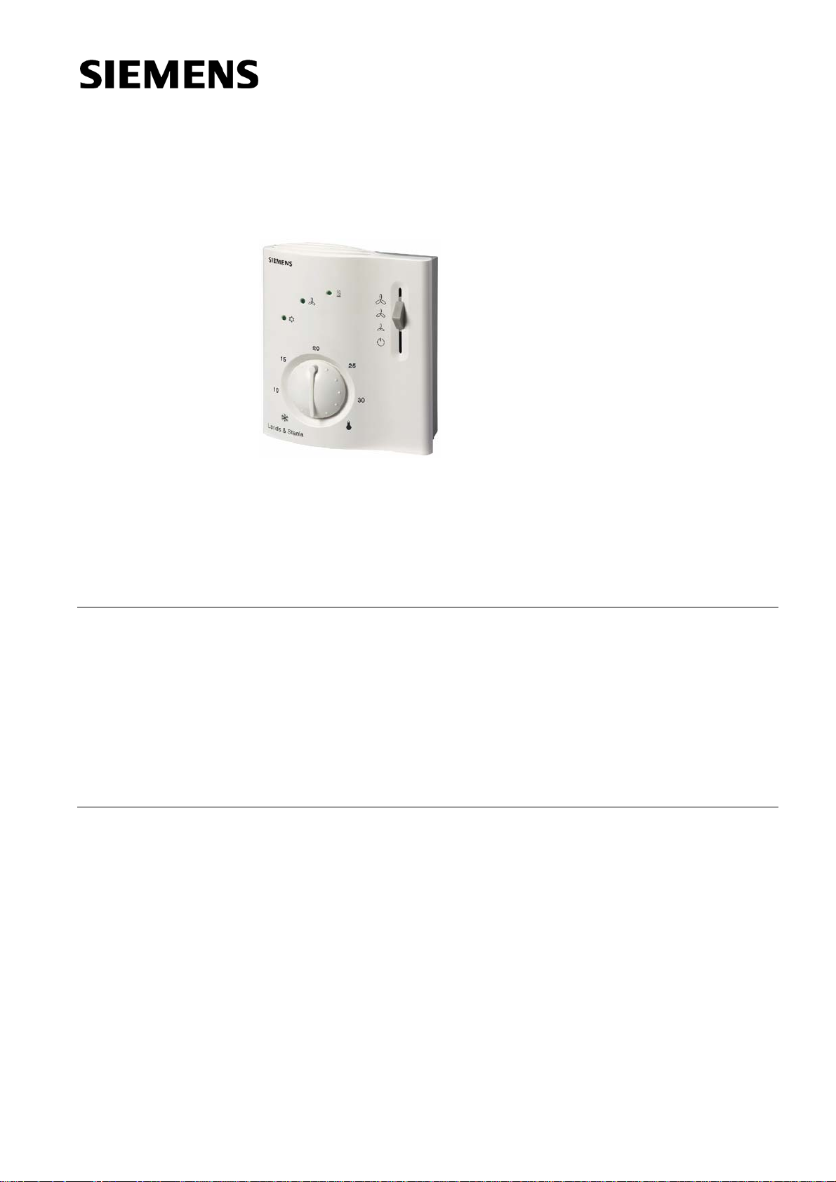
Room Temperature
RCC60.1
Controller
for two-pipe fan coil units
Modulating PI control
Output for three-position valve actuator
Outputs for three-speed fan
Automatic heating / cooling changeover
Operating modes: normal and energy saving or OFF
Operating mode changeover input for remote control
Function for avoiding damage resulting from moisture
Operating voltage AC 230 V
Use
CE1N3026en
12.06.2003
Typical use:
• Control of the room temperature in individual rooms that are heated or cooled with
two-pipe fan coil units.
• For opening and closing a three-position valve actuator operating on AC 230 V and
for switching a three-speed fan.
Suited for use in systems with
• automatic heating / cooling changeover
• continuous heating or cooling operation.
Siemens Building Technologies
HVAC Products
Page 2
Functions
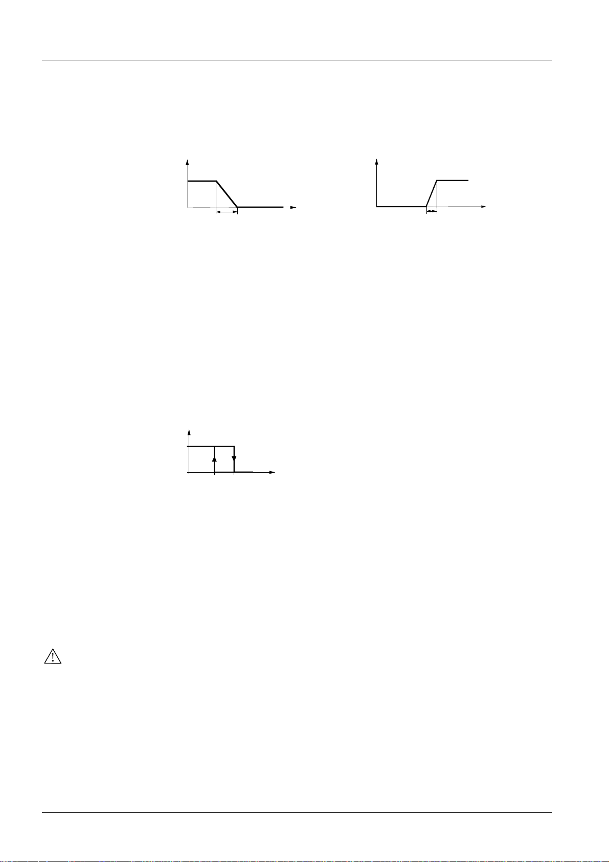
The controller acquires the room temperature with its integrated sensor and maintains
the setpoint by delivering three-position control commands to the valve. The controller
provides PI control. The proportional band in heating mode is 4 K and in cooling mode
2 K. The integration time is 5 minutes.
Heating mode Cooling mode
Y
Out
[%]
3026D02
100
Y
[%]
Out
3026 D01
100
Automatic
changeover
0
T Room temperature w Room temperature setpoint
XpH Proportional band heating YB
XpK Proportional band cooling
Note: the diagrams only show the proportional part of the PI controller
XpH
w
T [°C]
0
Manipulated variable
OutB
w
XpK
T [°C]
The water temperature acquired by the changeover sensor (QAH11.1 + ARG86.3) is
used by the controller to switch from heating to cooling mode, or vice versa. When the
water temperature lies above 28 °C, the controller switches to heating mode, below
16 °C it switches to cooling mode. If, immediately after switching on, the water temperature lies between the 2 changeover points, the controller will start in heating mode. The
water temperature is measured at minute-intervals and the operational status updated.
CM
HM
M
16 28
3026D03
TW [°C]
CM Cooling mode
HM Heating mode
Water temperature
TB
WB
M Operating mode
Purging function
Three-position
control signal
Energy saver
The task of the changeover sensor is to initiate the change from heating to cooling
mode even if the two-port valves are shut down for a longer period of time. To ensure
this function, the valves are opened for one minute at 2-hour intervals during off hours.
Outputs Y1 = opening, Y2 = closing and N = neutral are used to drive three-position
actuators with a maximum running time of 150 seconds from the fully closed to the fully
open position.
When commissioning the controller, an opening signal of 200 seconds is delivered,
followed by a closing signal of 200 seconds to ensure the actuator will be fully closed.
When the actuator has reached the position calculated by the controller, a waiting time
of 30 seconds is observed in order to stabilize the outputs.
The control outputs carry AC 230 V.
The room temperature setpoint can be limited in increments of 1 K by making use of
the minimum and maximum limitation facility. Arbitrary setpoint readjustments can thus
be prevented.
2/8
Siemens Building Technologies Room temperature controller CE1N3026en
HVAC Products 12.06.2003
Page 3

Fan operation
Operatingmodes
Normal operation
The fan is switched to the selected speed via control output Q1, Q2 or Q3.
When the function “Temperature-dependent fan control“ is activated (can be
selected with DIP switch no. 1), the fan is switched on / off depending on the
temperature, that is, together with the valve.
It is switched off by
• leaving the heating or cooling sequence, provided the function “Temperature-
dependent fan control “ is activated, or
• manually changing to OFF '
', or
• activating an external operating mode changeover switch, provided plant conditions
do not call for energy saving, or
• turning the controller’s power supply off
The following operating modes are available:
Heating or cooling mode with automatic changeover and with manually selected fan
speed III, II or I. In normal operation, the controller maintains the adjusted setpoint. In
operating mode selector position
, the controller is switched off.
Energy saving mode
Avoiding damage
resulting from moisture
Operating mode
changeover switch
Ordering
In energy saving mode, the setpoint of heating is 16 °C and the setpoint of cooling
28 °C, independent of the position of the setpoint knob. This operating mode will be
activated when input D1 for operating mode changeover is active and DIP switch
no. 2 is set to ON.
To avoid damage due to moisture in very warm or humid climatic zones resulting from
lack of air circulation in energy saving mode, DIP switch no. 1 must be set to OFF. With
this configuration, the fan is energy saving mode operates at the speed manually selected or, if the operating mode selector is set to OFF
, at speed I.
A changeover switch can be connected to status input D1-GND. When the switch
closes its contact (caused by an open window, for instance), the operating mode will
change from normal operation to energy saving mode (provided DIP switch no. 2 is set
to ON), or from normal operation to standby (provided DIP switch no. 2 is set to OFF).
When ordering, please give name and type reference.
The QAH11 temperature sensor (can be used as a changeover sensor), the changeover mounting kit and the valves are to be ordered as separate items.
Equipment combinations
Type of unit Type reference Data sheet
Temperature sensor
Changeover mounting kit
Motoric actuator (radiator valve)
Motoric actuator (small valve 2,5 mm)
Motoric actuator (small valve 5,5 mm)
Motoric actuator (valve 5,5 mm)
Motoric actuator (valve 5,5 mm)
Siemens Building Technologies Room temperature controller CE1N3026en
HVAC Products 12.06.2003
QAH11.1
ARG86.3
SSA31...
SSP31…
SSB31...
SSC31…
SQS35…
1840
1840
4893
4864
4891
4895
4573
3/8
Page 4
Mechanical design
The unit consists of two parts:
• A plastic housing which accommodates the electronics, the operating elements and
the built-in room temperature sensor
• A mounting base
The housing engages in the mounting base and snaps on.
The base carries the screw terminals. The DIP switches are located at the rear of the
housing.
Setting and
operating elements
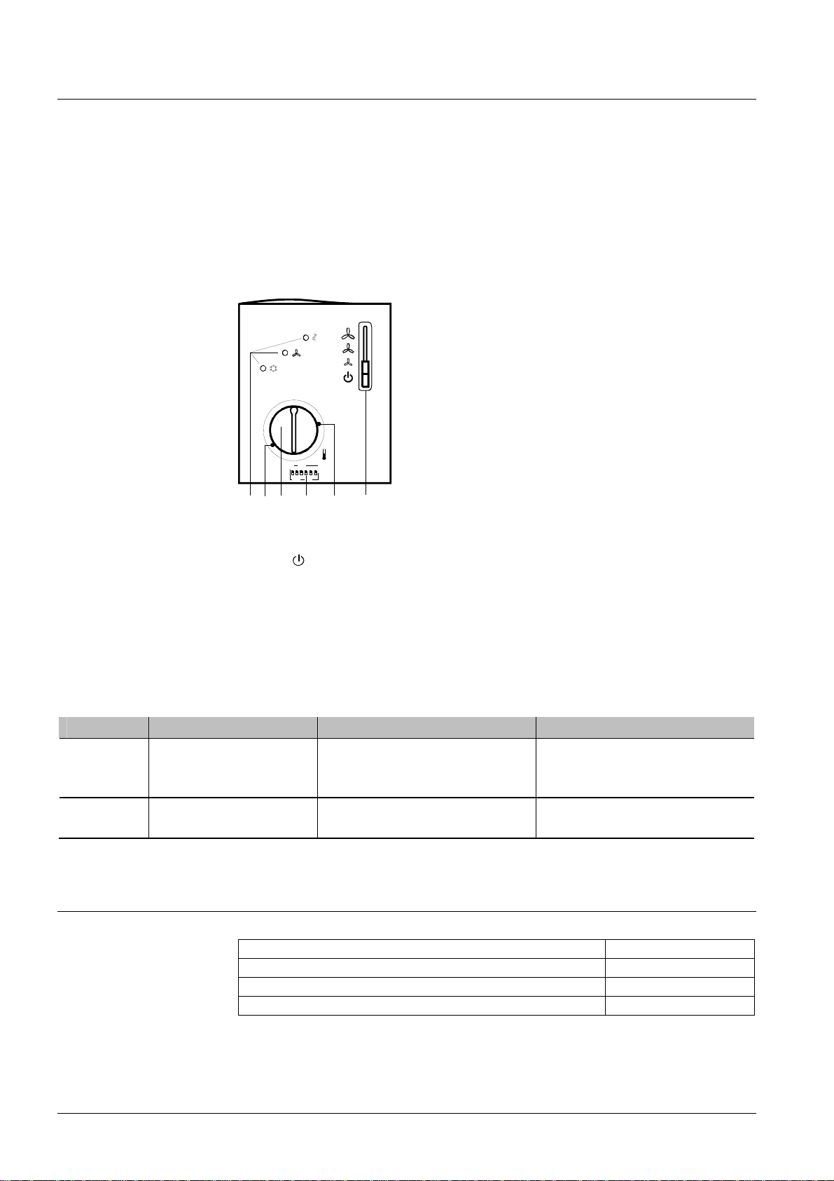
Legend
6 Set of DIP switches
3021Z01
256 13 4
1 Operating mode selector
(OFF
, heating or cooling mode with manual selection of fan speed)
2 LEDs for indicating heating mode, cooling mode and fan operation
3 Setting facility for minimum setpoint limitation
(in increments of 1 K)
4 Setting facility for maximum setpoint limitation
(in increments of 1 K)
5 Room temperature setpoint knob
DIP switch no. Meaning
1
2
Fan control
Operating mode changeover via external switch
1) Factory setting
Position ON
Fan control is temperaturedependent in normal operation and
energy saving mode
Changeover between normal operation and energy saving mode
Position OFF
Fan control in normal operation and
in energy saving mode is temperature-independent
1)
Changeover between normal operation and OFF
1)
Accessories
Description Type reference
Adapter plate 120 x 120 mm for 4“ x 4“ conduit boxes ARG70
Adapter plate 96 x 120 mm for 2“ x 4“ conduit boxes ARG70.1
Adapter plate for surface wiring 112x130 mm ARG70.2
4/8
Siemens Building Technologies Room temperature controller CE1N3026en
HVAC Products 12.06.2003
Page 5
Notes
Mounting, installation
and commissioning
In systems with automatic changeover, the temperature sensor can be replaced by an
external switch for manual changeover.
In systems with continuous heating operation, no sensor will be connected to the controller’s input.
With continuous cooling operation, the controller input (B2–M) must be bridged.
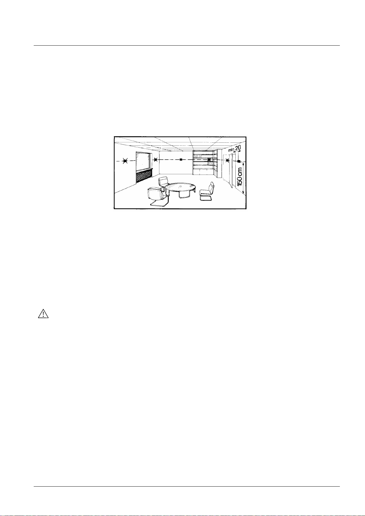
Mounting location: on a wall or inside the fan coil unit Not in niches or bookshelves, not
behind curtains, above or near heat sources and not exposed to direct solar radiation.
Mounting height is about 1.5 m above the floor. The connecting wires can be run to the
controller from a recessed conduit box.
Check the settings of the DIL switches no. 1 and no. 2 and change them, if required. If
setpoint limitation is required, use the minimum and maximum limitation facility (energy
saver).
After applying power, the controller makes a reset during which the fan LED flashes,
indicating that the reset has been correctly made. This takes about 3 seconds. Then,
the LED stops flashing and the controller will be ready to operate.
Before the controller starts its control action, it performs a three-position synchronization of the actuator. As a result, the actuator will be fully opened and then closed again.
This process takes 400 seconds. Then, the controller will be ready to operate.
• Prior to fitting the changeover sensor, thermal conductive paste must be applied to
the location on the pipe where the sensor is placed
• The cables used must satisfy the insulation requirements with regard to mains potential
• Sensor input B2-M carries mains potential. If the sensor’s cables must be extended,
the cables used must be suited for mains voltage
The controller is supplied with Mounting Instructions.
5/8
Siemens Building Technologies Room temperature controller CE1N3026en
HVAC Products 12.06.2003
Page 6
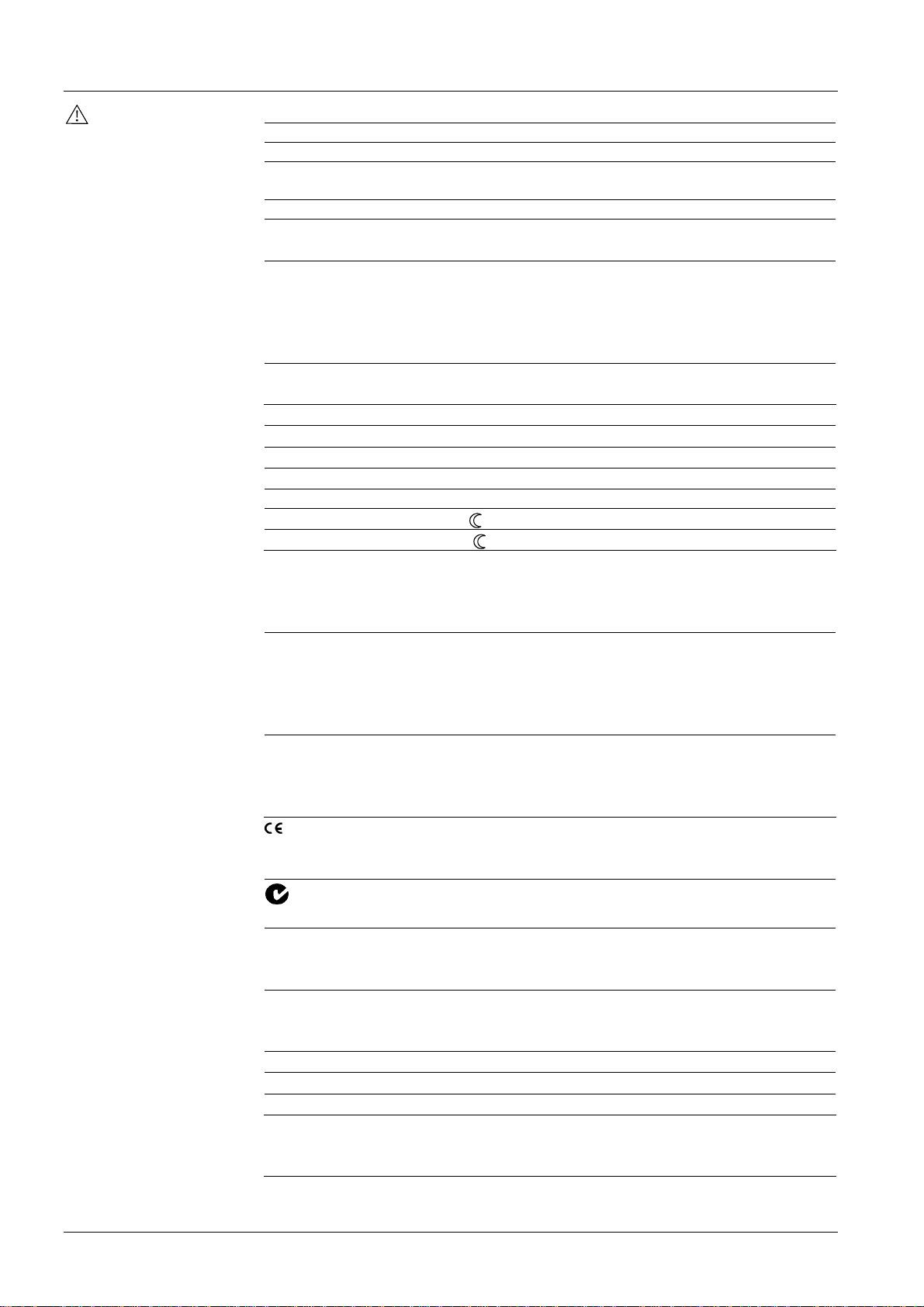
Technical data
Power supply
Operational data
Enivonmental conditions
Norms and standards
General
Operating voltage AC 230 V +10/- 1 5 %
Frequency 50/60 Hz
Power consumption max. 6 VA
Control outputs Q1, Q2, Q3
Rating
AC 230 V
max. 600 VA
Control outputs Y1, Y2 AC 230 V, 0.02…2 A
Signal input B2 for changeover-sensor QAH11.1, Safety class II
NTC resistor 3kΩ at 25°C
Status input D1
Contact sensing
Insulation against mains voltage
Max. number of contacts connected in parallel
Operating action
Perm. cable length with copper cable 1.5 mm
for connection to terminals B1, B2 and D1
SELV, DC 15 V
4 kV
50
N.O.
2
80 m
Setpoint setting range 8...30 °C
Max. control deviation at 25 °C max. ± 0.7 K
P-band in heating mode XpH 4 K
P-band in cooling mode XpK 2 K
Integration time 5 mi n
Setpoint «Energy saving mode », heating 16 °C
Setpoint « Energy saving mode », cooling 28 °C
Operation
Climatic conditions
Temperature
Humidity
Transport
Climatic conditions
Temperature
Humidity
Mechanical conditions
Storage
Climatic conditions
Temperature
Humidity
conformity to
EMC directive
Low voltage directive
N474
C-Tick conformity to
EMC emission standard
Product standards
Automatic electrical controls for household and
similar use
Electromagnetic compatibility
Emissions
Immunity
to IEC 721-3-3
class 3K5
0...+50 °C
<95 % r.h.
to IEC 721-3-2
class 2K3
− 25...+70 °C
<95 % r.h.
class 2M2
to IEC 721-3-1
class 1K3
− 25...+70 °C
<95 % r.h.
89/336/EEC
73/23/EEC and 93/68/EEC
AS/NSZ 4251.1:1994
EN 60 730 – 1 and
EN 60 730 – 2 - 9
EN 50 081-1
EN 50 082-1
Safety class II to EN 60 730
Pollution class normal
Degree of protection of housing IP30 to EN 60 529
Connection terminals Use solid wires or prepared
stranded wires.
2 x 0.4-1.5 mm
2
or 1 x 2.5 mm
2
6/8
Siemens Building Technologies Room temperature controller CE1N3026en
HVAC Products 12.06.2003
Page 7
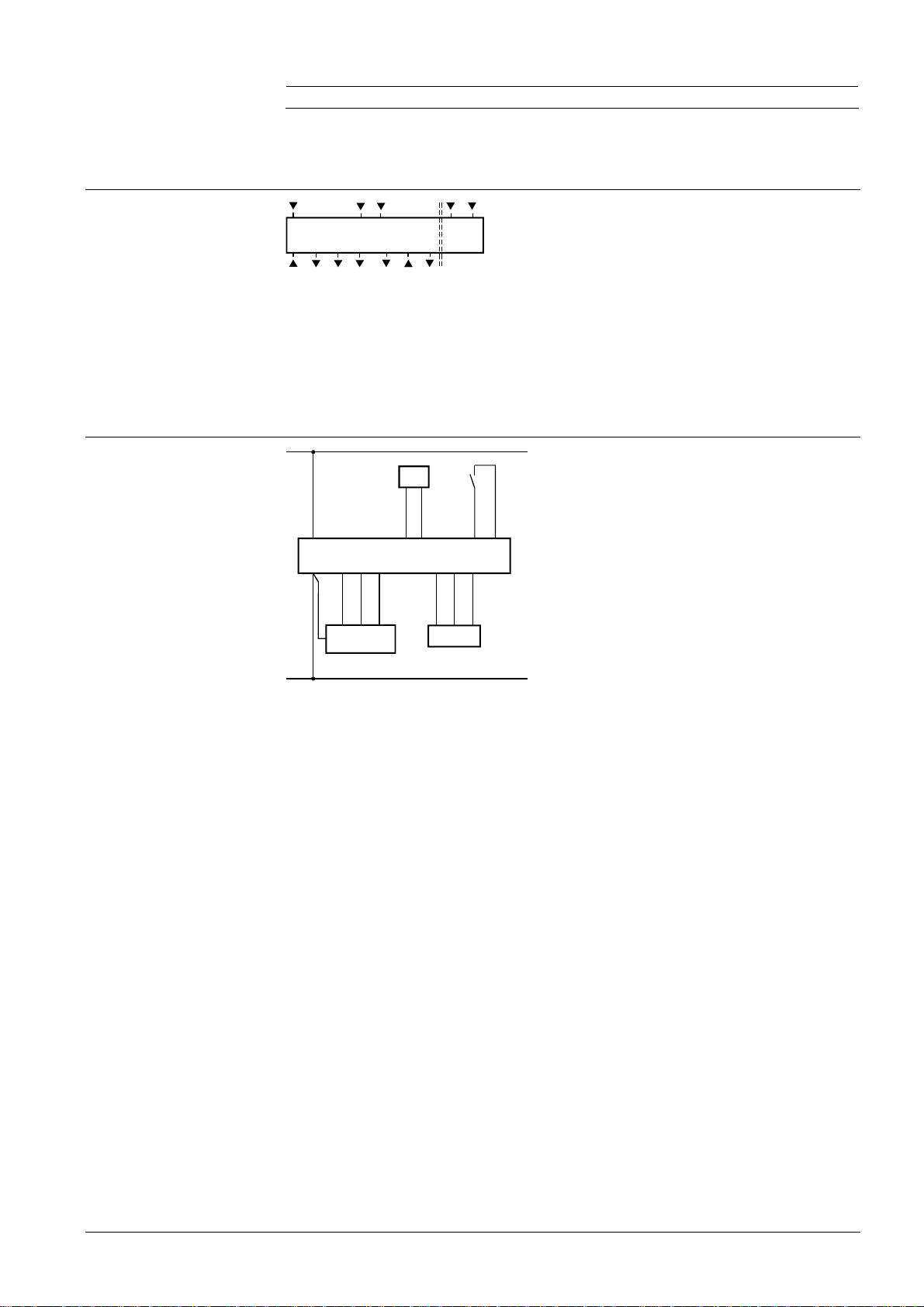
Connection terminals
Weight approx. 0.21 kg
Colour of housing front white, NCS S 0502-G (RAL9003)
Connection diagram
L
N
L
Q1 Q2 Q3
B2 M
Y1 N
D1 GND
Y2
SELV
B2
LB2MD1GND
Q1 Q2 Q3 N
N
I II III
N
N
Y1YY2
M1
S1
L, N Operating voltage AC 230 V
B2 Status input “Changeover sensor”
3026G01
M Measuring neutral “Changeover sensor”
D1, GND Status input for potential-free operating mode
changeover switch
Q1 Control output “Fan speed I“, AC 230 V
Q2 Control output “Fan speed II'“, AC 230 V
Q3 Control output “Fan speed III'“, AC 230 V
Y1 Control output “Open valve”, AC 230 V
Y2 Control output “Close valve”, AC 230 V
B2 Changeover sensor
3026A01
(QAH11.1 temperature sensor)
M1 Three-speed span
N1 RCC60.1 room temperature controller
S1 External operating mode changeover switch
Y Three-position valve actuator
N1
Y1 Control output “Open valve”, AC 230 V
Y2 Control output “ Close valve”, AC 230 V
7/8
Siemens Building Technologies Room temperature controller CE1N3026en
HVAC Products 12.06.2003
Page 8
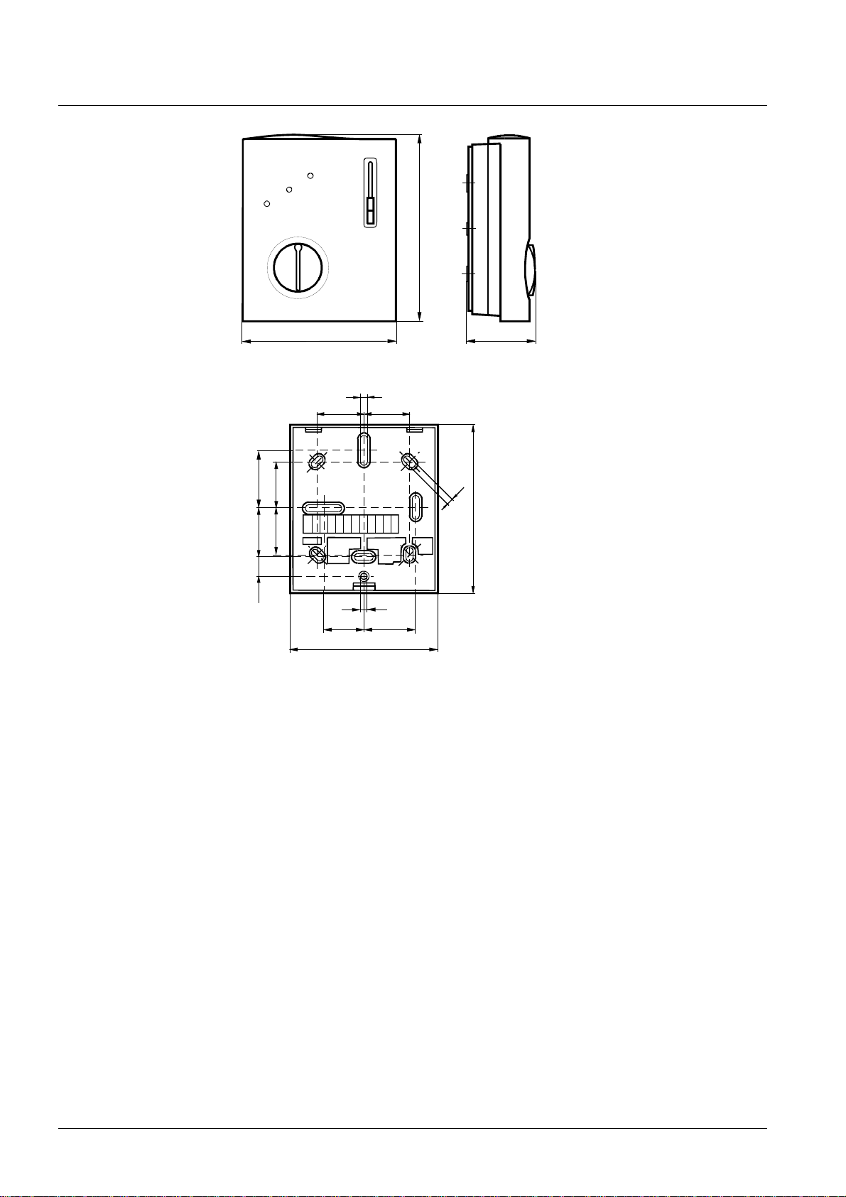
Dimensions
unit
baseplate
3021M01
114,15
96,6
42,8
4
28 28
3530
2828
4
104
11,8
26
90
4
30
3021M02
8/8
Siemens Building Technologies Room temperature controller CE1N3026en
HVAC Products 12.06.2003
© 2002 Siemens Building Technologies AG Subject to alteration
 Loading...