

Page 1
Installation Instructions
Model RCC-3/-3R/-3C/-3F/-3FC/-3FR
Remote Command Center
INTRODUCTION
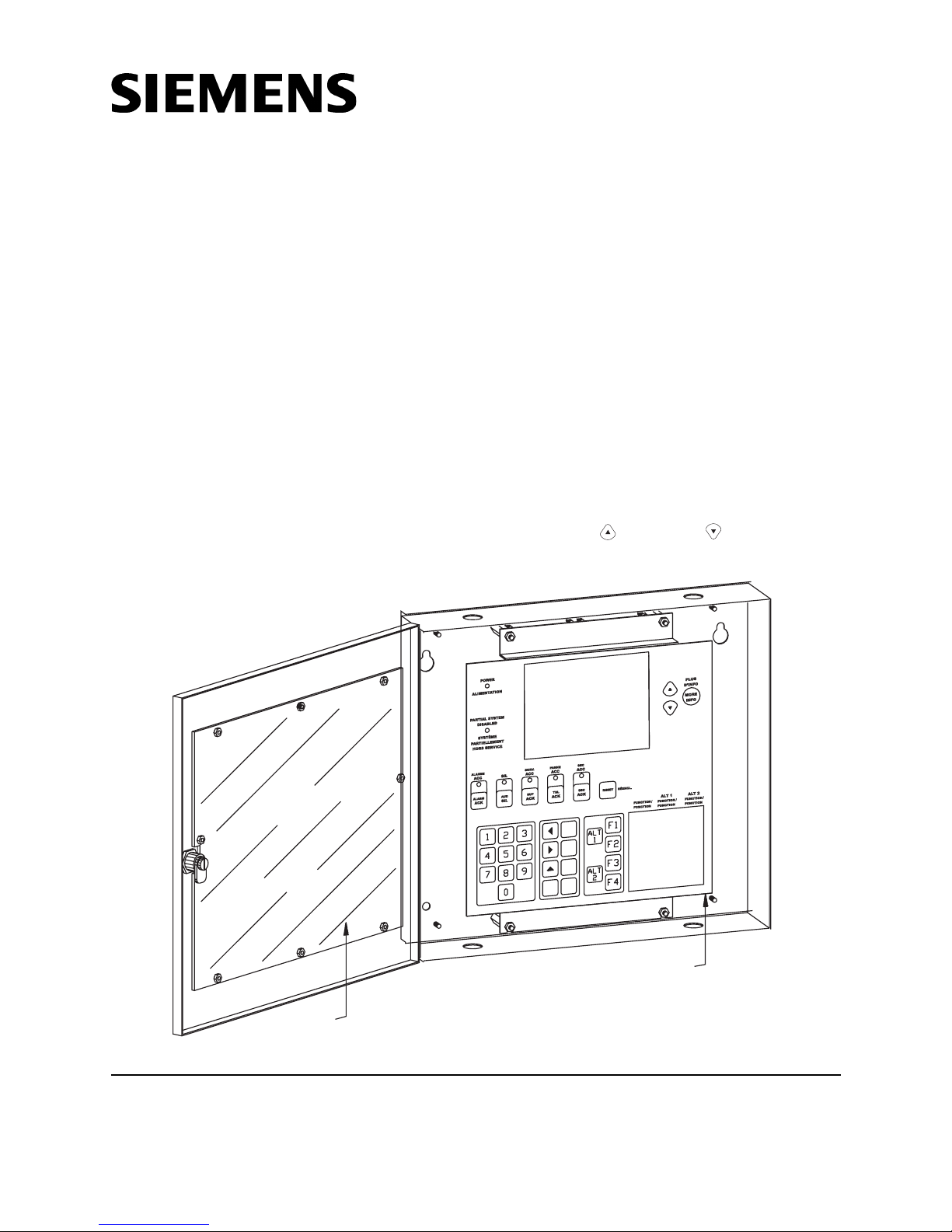
The Model RCC-3/-3R/-3C Remote Command
Center from Siemens Industry, Inc. is an optional
MXL/MXLV System remote keyboard panel (See
Figure 1). The RCC-3R is red and will be referred to in the remainder of this document as
the RCC-3. The RCC-3F/-3FC/-3FR Remote
Command Center, which is used for flush
mounting applications, has a 3/4 inch flange on
all four sides of the enclosure. The RCC-3FR is
red and will be referred to in the remainder of
this document as the RCC-3F.
CAUTION: When preparing the opening for the
RCC-3F/-3FC make sure it does not exceed the
dimensions of the enclosure as shown in Figure 2,
plus the dimensions of the flange.
The panel in the RCC-3/-3C/-3F/-3FC has a multiline display that continuously updates information
about the system event status. If there are
multiple events (alarms, security conditions,
supervisories and/or troubles), the highest
priority event that occurred displays on the
screen. The user can view up to 8 events at a
time and can scroll through the complete list
using the Up ( ) and Down ( ) keys located
next to the More Info key. For further information
Clear lens
RCC-3C/3FC Remote Command Center
Siemens Industry, Inc.
Building Technologies Division
Florham Park, NJ
P/N 315-048665-7
Figure 1
/
P
L
E
H
E
D
I
A
/
T
N
I
R
P
.
P
M
I
/
E
C
A
P
S
E
C
A
P
S
E
/
R
A
E
L
C
/
R
E
T
N
E
R
E
C
A
F
F
E
R
E
R
T
N
E
Keyboard/Display panel
Siemens Building Technologies, Ltd.
Fire Safety & Security Products
2 Kenview Boulevard
Brampton, Ontario
L6T 5E4 Canada
Page 2
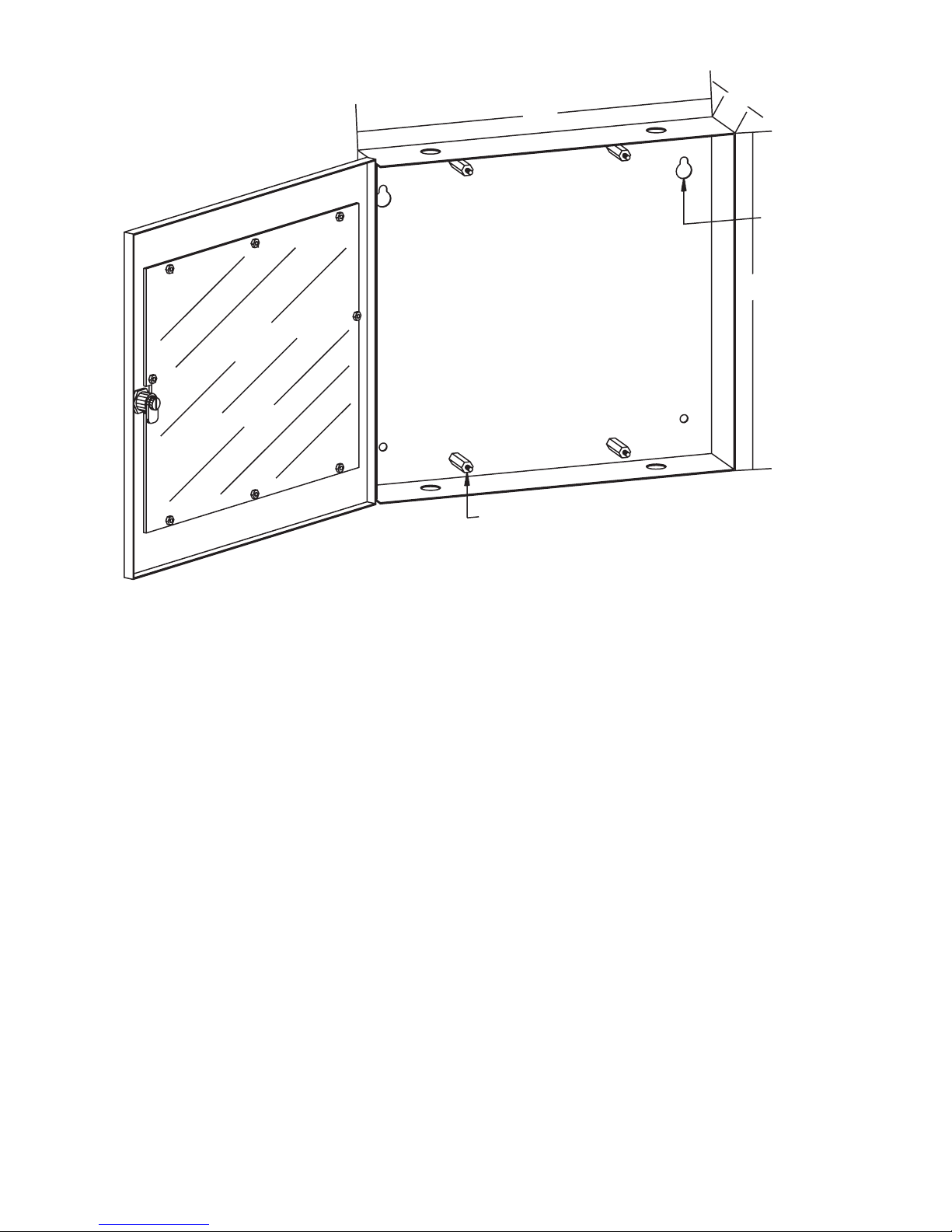
14"
Standoffs for
keyboard panel
2½"
13"
Mounting holes
(4 places)
Mounting the RCC-3/3F
on the operation of the MXL Multi-Line Keyboard/
Display Panel, refer to the MXL Keyboard/
Display Panel Operating Instructions, P/N 315048692, and Section 3, OPERATION, in the
MXL/MXLV Manual, P/N 315-092036.
The keyboard/display panel has keys for the
following functions:
• Acknowledging fire alarms (ALARM ACK)
• Silencing audibles (AUD SIL)
• Acknowledging supervisories (SUPV ACK)
• Acknowledging troubles (TRBL ACK)
• Acknowledging security conditions (SEC ACK)
There is also a separate key for resetting the
Control Panel (RESET)
The 10-digit phone style keypad allows entry of
the three levels of user passwords. It is also
used to perform specific menu-driven operations,
as well as programming and maintenance
functions.
Separate UP and DOWN keys located next to the
MORE INFO key allow the user to scroll forward
and backwards through the entire list of events.
Figure 2
The SPACE key allows the user to input addresses faster by enabling them to reduce
redundant key presses of the “0” key.
The MORE INFO key allows the user to instantly
view all relevant information about the highlighted
event, which is displayed in the last three lines of
the screen.
The user can access the MXL Control menu by
pressing the ENTER key.
The panel has System status indicator LEDs.
The ALARM and TROUBLE LEDs function even
if the main processor fails. (See Figure 1).
INSTALLATION
Always remove all power before installation,
first the battery and then the AC.
The RCC-3/-3C/3F/-3FC comes with the keyboard/display panel installed in the enclosure and
a clear lens installed in the door, as shown in
Figure 1.
2
Page 3
1 2 3 4 5
TO OPTION
MODULES
SERIAL
PRINTER
PARALLEL
PRINTER
1
J3
BACKLIGHT
VR2
BRIGHTNESS
J2 J1 J5
J10
SERIAL
PRINTER
1
PARALLEL
PRINTER
1
J11
LCD KEYBOARD LEDS
J13
J7
+
1
J12
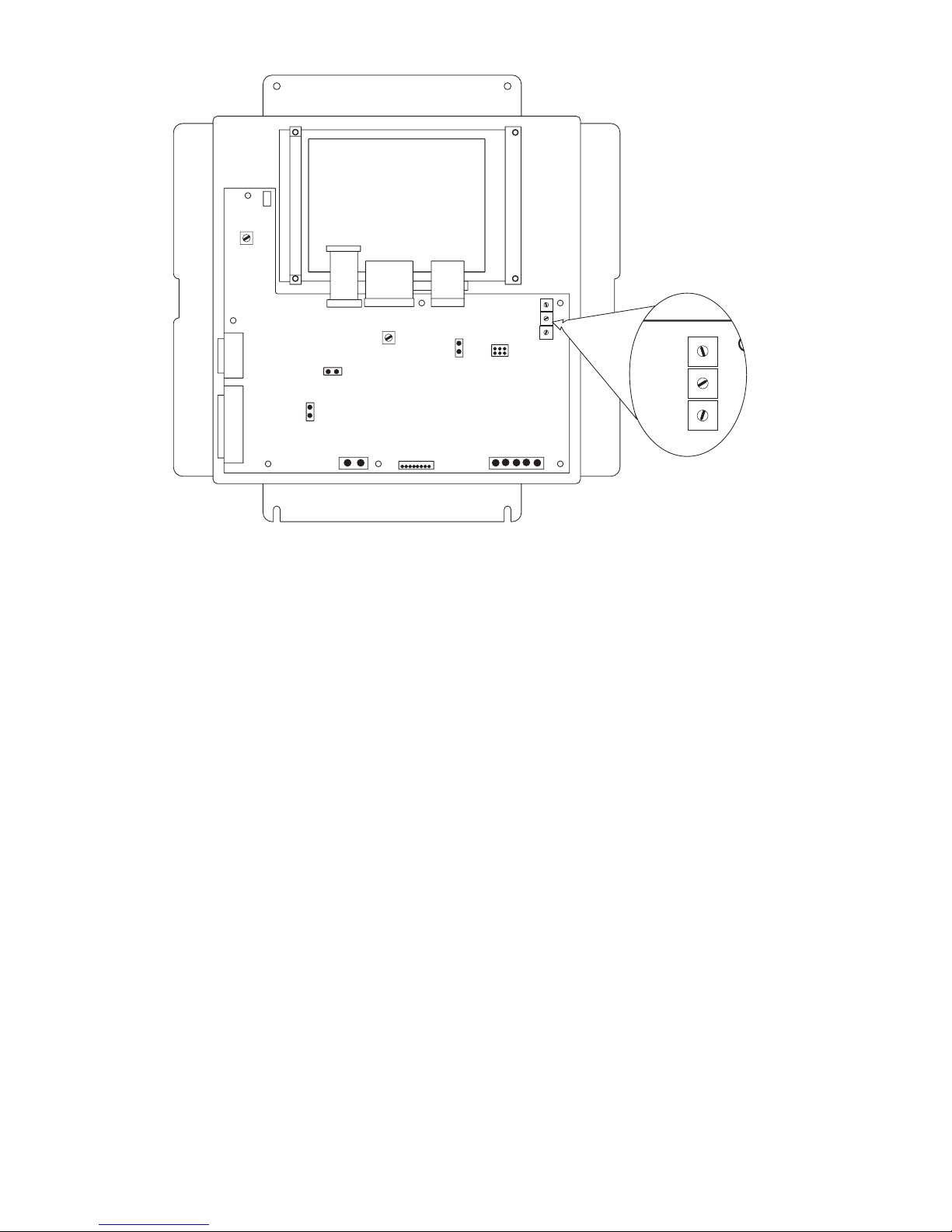
Rear View of Keyboard/Display Panel in RCC-3/3F
Before mounting the RCC-3/-3C/3F/-3FC,
remove the four nuts from the keyboard panel
and place them to one side. Carefully lift the
panel up and off the standoffs. Set the panel to
one side.
Consider the following when mounting the
backbox:
• Mounting height for visual and manual
access to the keyboard/display panel
• Weight and size of the enclosure
• Local mounting codes
1. Fasten the backbox securely to a clean, dry,
shock-free, and vibration-free surface using
the four mounting holes provided. Position
the backbox clear of obstructions so that the
door opens freely and the indicators and
controls are easily accessible.
2. Set the Network Address for the RCC-3
using the three ten-position rotary switches
(S1, S2 and S3) located on the back of the
keyboard/display panel, as shown in Figure 3.
For example, to set the switches to address
248: set S1 to 2, set S2 to 4, and set S3 to 8.
The possible addresses for this module are
248, 259, 250, and 251.
1
VR1
CONTRAST
_
2
J4
1
MODULES
1
1
J6
J9
NETWORKTO OPTION
12345
J8
Figure 3
3
2
4
1
5
0
6
9
S1
7
8
3
2
4
1
5
0
6
9
S2
7
8
3
2
4
1
5
0
6
9
S3
7
8
S1
S2
S3
3
2
4
1
5
0
6
9
7
8
3
2
4
1
5
0
6
9
7
8
3
2
4
1
5
0
6
9
7
8
NOTE:
There is no need to set supervision on the
RCC-3/-3C/3F/-3FC because it is, by default,
always supervised. No unsupervised
annunciators (MKB-1/-2/-3/-4) are allowed
at the same address as an RCC-3/-3C/3F/3FC. Unsupervised applications require the
use of the MKB-1/-2/-3/-4 and they must all
be set to the same address.
3. Pull all field wiring into the backbox and
dress the wiring to the approximate location
to which it will go.
4. Remove the connector plugs from J8. Attach
the wiring to the connector plugs in positions
1 and 2 for Style 4 (refer to Figure 4) and
positions 1, 2, 3 and 4 for Style 7 (refer to
Figures 5 and 6). Always connect position 5
to Chassis GND (Earth GND).
5. Remove the connector plugs from J12.
Attach the field wiring to the connector plugs,
making sure that position 1 on J12 is for
+24VDC and position 2 on J12 is for -24VDC
return.
6. To adjust the contrast and brightness of the
display, use pots VR1 and VR2 respectively,
located on the back of the keyboard /display
panel. (Refer to Figure 3.)
3
Page 4

POWER
MMB-1/-2:
120 OHMS, 1/4W, 5%
*
P/N 140-820150
MMB-3:
RES EOL ASSEMBLY
120 OHMS, 1/4W, 5%
P/N 140-049099
*
SERIAL PRINTER
PARALLEL PRINTER
TB1
4
3
2
1
SUPERVISION
NOTE:
INSTALL EITHERA SERIAL OR
PARALLEL PRINTER. ONLY ONE
PRINTER CAN BE CONNECTED
TO THE SYSTEM.
SUPERVISED BY DEFAULT
MMB
BACKLIGHT
OPTIONAL
SERIAL PRINTER
PARALLELPRINTER
For RCC-3/3 F Installation Only
1
J3
J10
J11
CHASSIS
GND
1
13
14
2
LCD
KEYBOARD
12 1
J2 J1
J12
12
+-
+24VDC
-24VDC
For 24 VDC connections, refer to the following terminations:
MMB
PSR-1
PLM-35 (Used with PS-35)
ALARMSAF (Model BN4-002-UL)
PAD-3
81
J4
TO OPTIONAL
MODULES
18
P/N 140-820150
120 OHMS, 1/4W, 5%
LEDS
J5
J8
NETWORK
12345
TB5, 9-12
TB3, 3-6
TB1, 1-2
DC1
TB2, 18-19
Notes:
1. Use a minimum wire gauge of 22 AWG.
2. Use a maximum of 80 ohms per pair of wires for
the network connections.
3. Use shielded twisted pair for network connections.
4. Terminate the shield ONLY at the MMB
enclosure.
5. For MMB-1/-2 Style 4, use a 120 Ohm, 1/4W,
5% EOLR, P/N 140-820150, in positions 1 and
2 on plug J8.
For MMB-3 Style 4, use Res EOL Assembly, 120
Ohm, 1/4W, 5%, P/N 140-049099.
6. This configuration is power limited to NFPA
70 according to NEC 760.
7. The RCC-3/-3C/-3F/-3FC MUST have an
earth ground connected to the chassis. Wire
shield or conduit is not an acceptable ground.
Use any available unused, unpainted stud on
the MMB for chassis grounding.
8. Refer to Wiring Specification for MXL, MXL-IQ
and MXLV Systems, P/N 315-092772 revision
6 or higher, for additional wiring information.
9. Maximum voltage: 8V peak to peak
Maximum current: 150mA
Figure 4
RCC-3/3F Style 4 Wiring
4
Page 5

POWER
P/N 140-820150
120 OHMS, 1/4W, 5%
TB1
SERIAL PRINTER
PARALLEL PRINTER
P/N 140-820150
120 OHMS, 1/4W, 5%
1
2
34
5678910111213141516
NET-7
NOTE:
INSTALL EITHER A SERIAL OR
PARALLEL PRINTER. ONLY ONE
PRINTER CAN BE CONNECTED
TO THE SYSTEM.
SUPERVISED BY DEFAULT
MOM-4
SUPERVISION
OPTIONAL
1
2
34
5678910111213141516
1
BACKLIGHT
SERIAL PRINTER
PARALLELPRINTER
J3
J10
J11
1
13
14
2
LCD
KEYBOARD
12 1
81
J2 J1
J12
12
+-
+24VDC
-24VDC
TB3
For 24 VDC connections, refer to the following terminations:
MMB
PSR-1
PLM-35 (Used with PS-35)
ALARMSAF (Model BN4-002-UL)
PAD-3
J4
TO OPTIONAL
MODULES
18
P/N 140-820150
*
120 OHMS, 1/4W, 5%
TO CHASSIS GND ON MMB-1/-2
LEDS
J5
J8
NETWORK
12345
**
TB5, 9-12
TB3, 3-6
TB1, 1-2
DC1
TB2, 18-19
1
2
34
5678910111213141516
TB2
1
2
34
Notes:
1. Use a minimum wire gauge of 22 AWG.
2. Use a maximum of 80 ohms per pair of
wires for the network connections.
3. Use shielded twisted pair for network
connections.
4. Terminate the shield ONLY at the MMB
enclosure.
5. For Style 7, use a 120 Ohm, 1/4W, 5%
EOLR, P/N 140-820150, in positions 1 and 2
and positions 3 and 4 on plug J8.
6. For Style 7, use a NET-7 card and refer to the
NET-7 Installation Instructions, P/N 315-090914.
7. The NET-7 is not compatible with the PS-5N.
RCC-3/3F Style 7 Wiring (MMB-1 or MMB-2)
5678910111213141516
TB4
8. This configuration is power limited to NFPA
70 according to NEC 760.
9. The RCC-3/-3C/-3F/-3FC MUST have an earth
ground connected to the chassis. Wire shield or
conduit is not an acceptable ground. Use any
available unused, unpainted stud on the MMB
for chassis grounding.
10. Refer to Wiring Specification for MXL, MXL-IQ
and MXLV Systems, P/N 315-092772 revision
6 or higher, for additional wiring information.
11. Maximum voltage: 8V peak to peak
Maximum current: 150mA
Figure 5
5
Page 6

POWER
SERIAL PRINTER
PARALLEL PRINTER
TB1
SUPERVISION
NOTE:
INSTALL EITHER A SERIAL OR
PARALLEL PRINTER. ONLY ONE
PRINTER CAN BE CONNECTED
TO THE SYSTEM.
SUPERVISED BY DEFAULT
OPTIONAL
1
BACKLIGHT
SERIAL PRINTER
PARALLELPRINTER
CHASSIS
J3
J10
J11
GND
13
14
LCD
J2 J1
+-
+24VDC
-24VDC
1
2
KEYBOARD
12 1
J12
12
120 OHMS, 1/4W, 5%
81
LEDS
J5
J4
TO OPTIONAL
MODULES
18
P/N 140-820150
*
TO CHASSIS GND ON MMB-3
J8
NETWORK
12345
**
RES EOL ASSEMBLY
120 OHMS, 1/4W, 5%
P/N 140-049099
RES EOL ASSEMBLY
120 OHMS, 1/4W, 5%
P/N 140-049099
4
3
2
1
Notes:
1. Use a minimum wire gauge of 22 AWG.
2. Use a maximum of 80 ohms per pair of
wires for the network connections.
3. Use shielded twisted pair for network
connections.
4. Terminate the shield ONLY at the MMB
enclosure.
5. For Style 7, use Res EOL Assembly 120 Ohm,
1/4W, 5%, P/N 140-049099, in positions 1
and 2 and positions 3 and 4 on plug J8.
6. This configuration is power limited to NFPA
70 according to NEC 760.
For 24 VDC connections, refer to the following terminations:
MMB
PSR-1
PLM-35 (Used with PS-35)
ALARMSAF (Model BN4-002-UL)
PAD-3
MMB-3
7. The RCC-3/-3C/-3F/-3FC MUST have an earth
ground connected to the chassis. Wire shield or
conduit is not an acceptable ground. Use any
available unused, unpainted stud on the MMB
for chassis grounding.
8. Refer to Wiring Specification for MXL, MXL-IQ
and MXLV Systems, P/N 315-092772 revision
6 or higher, for additional wiring information.
9. MNET:
Maximum Voltage: 8V Peak To Peak
Maximum Current: 150mA
TB5, 9-12
TB3, 3-6
TB1, 1-2
DC1
TB2, 18-19
Figure 6
RCC-3/3F Style 7 Wiring (MMB-3)
6
Page 7

7. If needed, J11 is the connector for a parallel
printer and J10 is the connector for a serial
printer. The serial connection can be
supervised; the parallel connection is
supervised by default. Note that only one
printer, either parallel or serial, may be
connected to the system.
Supervision for the printer is set in CSG-M. In
the Network Module Map, select the MKB and
press Enter. Scroll down to Printer Option and
press Enter to toggle to the correct printer. The
fields Supervised Operation and Serial Port
must both be set to YES.
8. Make certain the connector plugs are in place
on J13 for normal operation and network
programming.
9. Mount the keyboard panel in the enclosure by
placing it on the standoffs and securing it in
place with the four nuts provided.
10. Refer to the MXL Multi-Line Display/Panel
Operating Instructions, P/N 315-048692, for
additional information on the operation of the
keyboard panel.
11. Refer to MMB-3 Installation Instructions,
P/N 315-048860, Configuration and MNET
sections to configure the MMB-3 and CSGM
for Style 4/7 wiring.
CCU/M and RDM-1 Wiring
to MKB-5/-6 or RCC-3
CCU/M OR RDM-1
RXD
TXD
GND
DSR
CTS
RCC-3
J10
2
3
5
6
8
MXL-VDT Wiring
to MKB-5/-6 or RCC-3
RCC-3
J10
RXD
2
TXD
3
GND
5
DSR
6
CTS
8
DB9
PORT C
RXD
2
TXD
3
DTR
4
GND
5
RTS
7
MXL-VDT
MAIN PORT
RXD
3
TXD
2
DTR
20
GND
7
RTS
4
DB24
ELECTRICAL RATINGS
tnerruCeludoMCDV5evitcAAm0
tnerruCeludoMCDV42evitcAAm003
tnerruCeludoMCDV42ybdnatSAm003
Refer to the following Installation Instructions
as needed:
MMB-2 P/N 315-095097
MMB-3 P/N 315-048860
NET-7 P/N 315-090914
MXL/MXLV Manual P/N 315-092036
7
Page 8

Siemens Industry, Inc.
Building Technologies Division
Florham Park, NJ
P/N 315-048665-7
Siemens Building Technologies, Ltd.
Fire Safety & Security Products
2 Kenview Boulevard
Brampton, Ontario
L6T 5E4 Canada
 Loading...