

Page 1
RCC10U
Technical Instructions
Document No. 155-712
September 27, 2007
Room Temperature Controller
for Two-pipe Fan Coil Units
Siemens Industry, Inc.
Description
Room temperature controller for two-pipe fan coil units.
Features
• Output for on/off valve actuator.
• Output for three-speed fan.
• Dual setpoint temperature scale.
• Control depending on the room or return air temperature.
• Automatic Heating/Cooling changeover.
• Operating modes: Normal, Energy Saving, Freeze Protection and Off.
• Operating mode changeover input for remote control.
• Selectable control parameters.
• Operating voltage 120 Vac.
Application
Typical use:
• Controlling room temperature in individual rooms that are heated or cooled with twopipe fan coil units.
• Opening or closing a valve
• Switching a three-speed fan.
Suitable for use in systems with:
• Automatic Heating/Cooling changeover.
• Heating only/Cooling only or Heating and Cooling applications.
Product Number
RCC10U With input for return air temperature sensor
Page 2
Technical Instructions RCC10U Room Temperature Controller
Document Number 155-712 for Two-pipe Fan Coil Units
September 27, 2007
Page 2 Siemens Industry, Inc.
Accessories
ARG70 Adapter plate, for 2-inch × 4-inch or 4-inch × 4-inch electrical wall boxes
QAH11.1 Changeover/remote sensor
141-570 Lockable Thermostat Guard
Ordering
The QAH11.1 temperature sensor (which can be used as a return air temperature or
changeover sensor), and valves must be ordered separately. An ARG70 Wall Box
Adapter (used to mask the drywall when mounting the controller to a 2-inch × 4-inch or
4-inch × 4-inch electrical wall box) must also be ordered separately.
Table 1. Equipment Combinations.
Product Number
Description
Technical Instructions
QAH11.1
Temperature Sensor
155-329P25
599 Series
Two-way and Three-way
Zone Valves
155-320P25
SF Series
Zone Valve Actuator
155-321P25
Warning/Caution Notations
WARNING:
Personal injury, or loss of life may occur if you do not follow a
procedure as specified.
CAUTION:
Equipment damage, or loss of data may occur if you do not
follow a procedure as specified.
Functions
The controller measures the room temperature with its integrated sensor or external
return air temperature sensor (QAH11.1)—if used—and maintains the setpoint by
delivering control commands to the two-position (on/off) valve.
The switching differential is adjustable; it can be 2°F (1°C) or 7°F (4°C) in Heating
mode, or 1°F (0.5°C) or 3.5°F (2°C) in Cooling mode.
Fan Operation
The fan is switched to the selected speed via control output 11, 10 or 9 (Low, Medium
or High).
When the Temperature-dependent fan control function is activated (can be selected
with DIP Switch No. 1), the fan and valve are switched ON or OFF depending on the
temperature.
It is switched OFF by:
• Leaving the Heating or Cooling sequence, if the function Temperature-dependent
fan control is activated.
• Manually changing to Standby , if room conditions do not call for Freeze Protection
mode.
• Activating an external operating mode changeover switch, if installation conditions
do not call for Energy Saving or Freeze Protection mode.
• Turning the controller’s power supply OFF.
Page 3
RCC10U Room Temperature Controller Technical Instructions
for Two-pipe Fan Coil Units Document Number 155-712
September 27, 2007
Siemens Industry, Inc. Page 3
Heating/Cooling Mode
Output terminals 7 and 5 (neutral) command the control valve.
Output terminals 7 and 5 are open (0 Vac) when:
1. The measured room temperature is at half the switching differential below the
setpoint (Heating mode), and
2. The valve has been fully closed for more than one minute.
Output terminals 7 and 5 are closed (120 Vac) when:
1. The measured room temperature is at half the switching differential above the
setpoint (Heating mode), and
2. The valve has been fully open for more than one minute.
NOTE: Output terminals 7 and 5 deliver a control command only for fail-safe open
(Normally Open) valve/actuator assemblies. Fail-safe closed (Normally
Closed) valve/actuator assemblies cannot be used with the RCC10U
Controller.
Return Air Temperature
The RCC10U provides control based on either the measured room temperature or the
fan coil unit’s return air temperature.
Changeover is automatic if a QAH11.1 cable temperature sensor is connected to the
device. Place the sensor in the return air duct and terminate to the controller.
Order the QAH11.1 separately for return air sensing.
Automatic
Heating/Cooling
Changeover
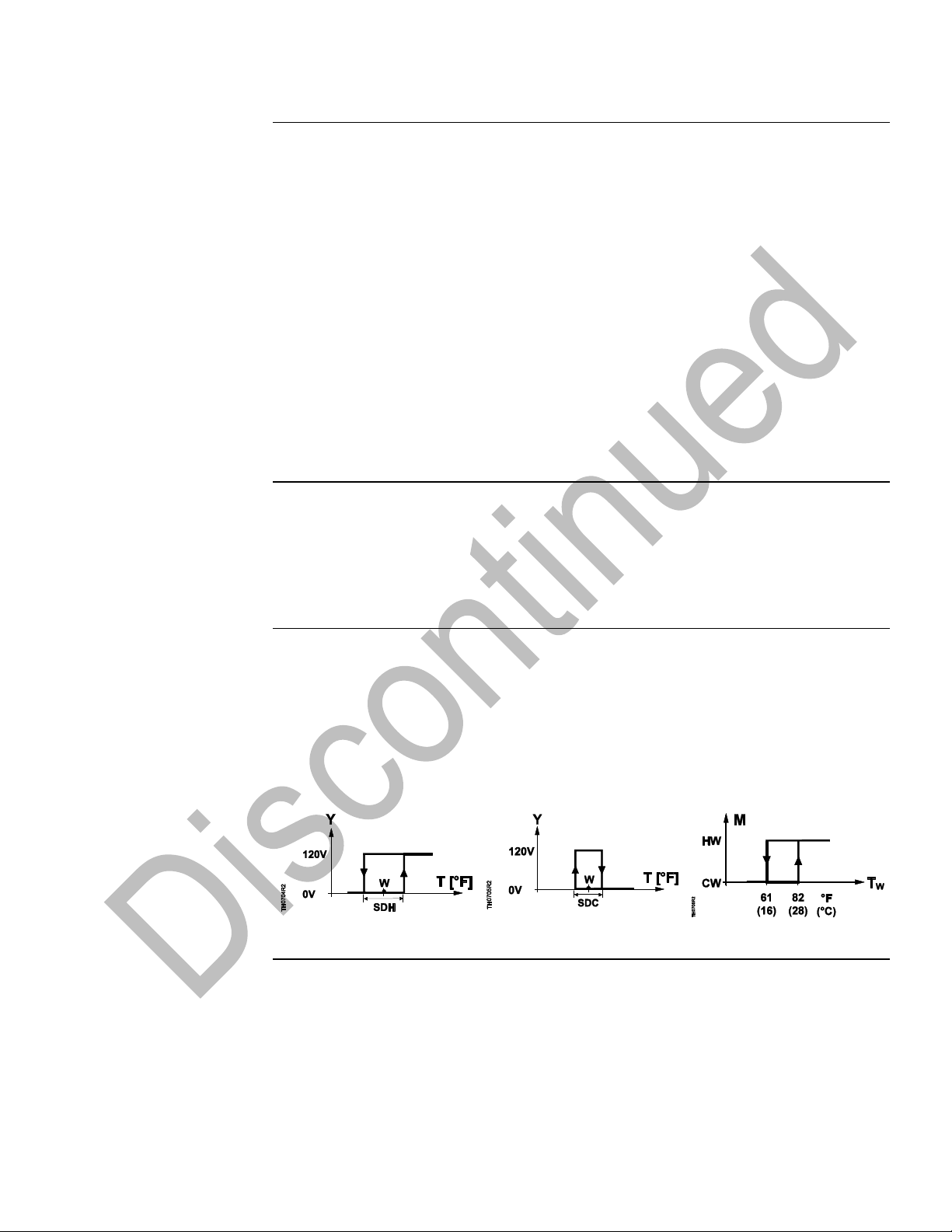
CW = Chilled Water Cooling
mode
HW = Hot Water Heating
mode
M = Operating mode
SDC = Switching differential,
cooling
SDH = Switching differential,
heating
T = Room temperature
Tw = Water temperature
W = Room temperature
setpoint
Y = Signal voltage
The controller uses the water temperature measured by the changeover sensor
(QAH11.1) to switch from Heating to Cooling mode, or vice versa. When the water
temperature is above 82°F (28°C), the controller switches to Heating mode; below 61°F
(16°C) it switches to Cooling mode. If the water temperature is between the two
changeover points immediately after switching on, the controller will start in the Heating
mode. The water temperature is measured at one-minute intervals and the operational
status is updated.
Heating Mode
Cooling Mode
Automatic Changeover
Figure 1. Switch Action for Output Teminals 7 and 5.
Remote Changeover
Heating/Cooling
An electric switch placed between input terminals 2 and 3 can
facilitate remote changeover. Terminals 2 and 4 must be bridged.
When the switch is closed, the Cooling mode is selected. When the
switch is open, the Heating mode is selected. Up to ten thermostats
can be connected in parallel.
Heating only
For heating only applications, input terminals 2 and 3 are open.
Cooling only
For cooling only applications, input terminals 2 and 3 must be
bridged with wire.
Page 4
Technical Instructions RCC10U Room Temperature Controller
Document Number 155-712 for Two-pipe Fan Coil Units
September 27, 2007
Page 4 Siemens Industry, Inc.
Purging Function
The changeover sensor initiates the change from Heating to Cooling mode even if the
two-way valves are shut down for a long period of time. To ensure this function, the
valves are opened for one minute at two-hour intervals.
After power is reset to the controller, the heating and cooling valve will open for one
minute to flush pipes, for accurate remote changeover sensing. When this function is
completed, the changeover sensor will select the correct mode.
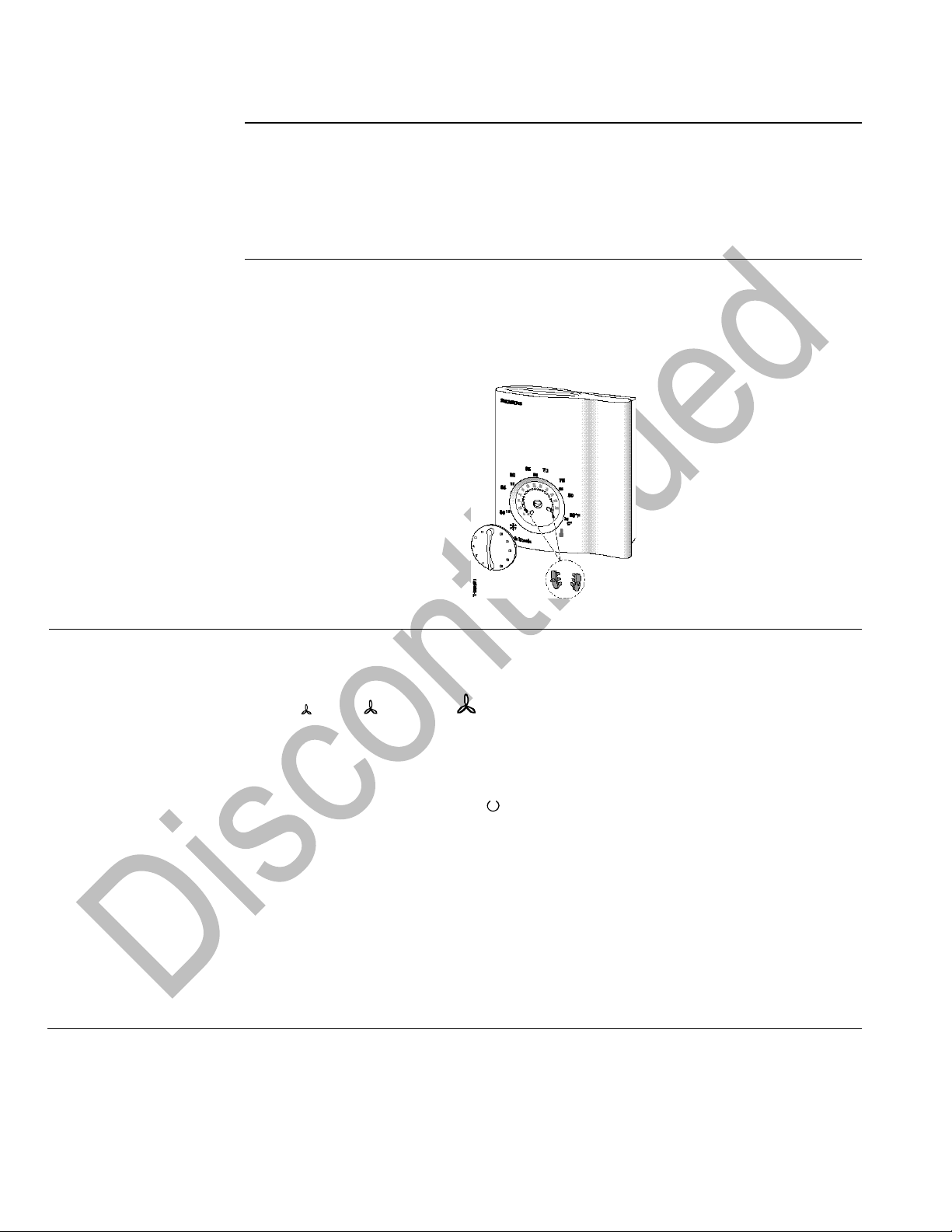
Setpoint Limit Stops
The room temperature setpoint can be limited in increments of 2°F (1°C) by using the
minimum and maximum setpoint limit stops. This prevents unauthorized setpoint
adjustment.
To set limit stops, remove the setpoint knob by pulling straight off the shaft. Reposition
gray tabs for high and low stops in the holes around the perimeter of knob as required.
See Figure 2.
Figure 2. Setpoint Limit Stops.
Operating Modes
The following operating modes are available:
Normal Operating Mode
Heating or Cooling mode with automatic changeover and with manually selected fan
speed: (Low), (Medium), (High). In Normal operation, the controller maintains
the adjusted setpoint.
Freeze Protection Mode
The Freeze Protection function is activated only when DIP Switch No. 4 is set to OFF.
Freeze Protection mode can be activated by:
• Manually switching to Standby .
• Activating the external operating mode changeover switch, if DIP Switch No. 2 is set
to OFF.
If the room temperature falls below 46°F (8°C), the controller will automatically switch to
Freeze Protection mode. In that case, the heating valve opens and the fan operates at
the selected speed. If the Standby mode is selected, the fan will operate at low speed.
The room temperature is maintained at a setpoint of 46°F (8°C) and the setpoint
adjusted by the user will be ignored.
If Freeze Protection operation is locked (DIP Switch No. 4 in position ON), Standby is
also locked, which means that the controller will switch to OFF instead of Standby.
Page 5

RCC10U Room Temperature Controller Technical Instructions
for Two-pipe Fan Coil Units Document Number 155-712
September 27, 2007
Siemens Industry, Inc. Page 5
Energy Saving Mode
In Energy Saving mode, the heating setpoint is 61°F (16°C) and the cooling setpoint is
82°F (28°C), independent of the position of the setpoint knob. This operating mode will
be activated when input D1 for operating mode changeover is active and DIP Switch
No. 2 is set to ON.
When the DIP switch is in Energy Saving mode and the fan speed control is set to
Standby, the Energy Saving mode takes precedence over Standby mode. When the
room temperature drops below the Energy Saving setpoint, the fan operates at low
speed until the energy load is satisfied; then the fan turns off. Low fan speed will be
selected even though the fan switch is on Standby.
Operating Mode
Changeover Switch
A changeover switch can be connected to status input D1–GND. When the switch
closes its contact (such as, caused by an open window), the operating mode will
change from Normal operation to Energy Saving mode (if DIP Switch No. 2 is set to
ON), or from Normal operation to Standby (if DIP Switch No. 2 is set to OFF). If the
room temperature falls below 46°F (8°C) and if DIP Switch No. 4 is set to OFF, Freeze
Protection mode will become active.
The operating action of the switch (NC or NO) can be selected by DIP Switch 3.
Mechanical Design
The unit consists of two parts:
• A plastic housing which accommodates the electronics, the operating elements and
the built-in room temperature sensor.
• A controller base.
The housing snaps into the top of the mounting base and is secured with a screw at the
bottom.
The wire terminal block is mounted on the base; the DIP switches are located at the
rear of the housing.
To access the DIP switches, remove controller from controller base. See Figure 3.
Figure 3. DIP Switch Setting.
Page 6

Technical Instructions RCC10U Room Temperature Controller
Document Number 155-712 for Two-pipe Fan Coil Units
September 27, 2007
Page 6 Siemens Industry, Inc.
Table 2. DIP Switches.
DIP Switch No.
Description
Position ON
Position OFF
1
Fan control
Fan control is temperaturedependent in all operating modes
Fan control in Normal
operation is temperatureindependent1
2
Operating mode changeover
via an external switch
Changeover between Normal
operation and Energy Saving
mode
Changeover between Normal
operation and Standby1
3
Operating action of switch for
external operating mode
changeover
Changeover activated when
contact of switch is closed (NO)1
Changeover activated when
contact of switch is open (NC)
4
Standby
Freeze Protection function
disabled
Freeze Protection function
enabled
5
Switching differential
2°F (1°C) in Heating mode
1
1°F (0.5°C) in Cooling mode1
7°F (4°C) in Heating mode
3.5°F (2°C) in Cooling mode
1. Factory setting
Construction
1 Standby mode selector /fan speed switch: (Low), (Medium), (High).
2 LEDs for indicating Heating mode, Cooling mode and fan operation.
3 Setting for minimum setpoint limit stop (in increments of 2°F [1°C]).
4 Setting for maximum setpoint limit stop (in increments of 2°F [1°C]).
5 Room temperature setpoint knob.
6 Set of DIP switches (mounted on circuit board).
Figure 4. Construction.
Page 7

RCC10U Room Temperature Controller Technical Instructions
for Two-pipe Fan Coil Units Document Number 155-712
September 27, 2007
Siemens Industry, Inc. Page 7
Mounting,
Installation and
Commissioning
• The unit can be located on a wall or inside a fan coil unit. Do not mount in direct
sunlight or near other heat or refrigeration sources.
• Mounting height is approximately 60 inches (150 cm) above the floor, when using
the wall mounting option. See Figure 5.
• The unit can be fitted to most commercially available recessed electrical wall boxes
or directly on the wall. A Wall Box Adapter Kit (ARG70), ordered separately, is
recommended but not required to mount an RCC10U controller to a
2-inch × 4-inch electrical wall box. An ARG70 is required for 4-inch × 4-inch electrical
wall box mounting. The wall plate will cover the drywall cutout.
• Check the settings of the DIP switches and change them, if required.
• After applying power, the controller makes a reset during which the fan LED flashes
indicating that the reset has been accomplished. This takes about three seconds.
When the LED stops flashing, the controller is ready to operate.
Figure 5. Acceptable Mounting Height in Inches.
• Prior to fitting the changeover sensor, apply thermal conductive paste on the pipe
where the sensor is to be placed. Secure with plastic cable ties.
• The sensor is not position sensitive.
• The cables used must meet the insulation requirements for live voltage.
• The control valve is fully open for one minute upon start-up to determine if it is in
Heating or Cooling mode (purging function).
• User input via setpoint knob or operating mode/fan speed selector results in
instantaneous response. There is a one-minute delay before changes made to
temperature sensing and changeover are implemented.
WARNING:
Sensor inputs 1, 2 and 3 carry live voltage potential. If the sensor’s cables
must be extended, the cables used must be suited for live voltage.
• Installation Instructions are included with the controller.
Page 8

Technical Instructions RCC10U Room Temperature Controller
Document Number 155-712 for Two-pipe Fan Coil Units
September 27, 2007
Page 8 Siemens Industry, Inc.
Installation
Instructions
4-inch × 4-inch Electrical
Wall Box Mounting
An ARG70 wall plate adapter is required to mount an RCC10U controller to a 4-inch ×
4-inch electrical wall box.
1. Loosen the screw at the bottom of the controller with a small screwdriver.
2. Lift the bottom of the controller from the controller base and push up to remove.
Figure 6. Controller Separation.
3. Fasten the wall box adapter (3) to plaster ring (2), supplied by others, using the four
screws provided with the ARG70.
4. Flex adapter mask (4) and snap in place inside wall box adapter (3).
5. Pull wires through plaster ring (2).
6. Fasten controller base (5), to wall box adapter assembly (3) and (4) with the two
screws provided.
Figure 7. 4-inch × 4-inch Electrical Wall Box Installation.
1 Electrical wall box
2 Plaster ring
3 Wall box adapter*
* Included with ARG70
4 Adapter mask*
5 Controller base
6 Controller
Page 9

RCC10U Room Temperature Controller Technical Instructions
for Two-pipe Fan Coil Units Document Number 155-712
September 27, 2007
Siemens Industry, Inc. Page 9
4-inch × 4-inch Electrical
Wall Box Mounting,
Continued
7. Terminate wires per wiring instructions located above the terminal block.
Figure 8. Wiring Termination.
8. Reattach the controller to the controller base.
9. Secure by tightening the screw at the bottom of the controller.
Figure 9. Controller Reattachment.
The installation is now complete.
Page 10

Technical Instructions RCC10U Room Temperature Controller
Document Number 155-712 for Two-pipe Fan Coil Units
September 27, 2007
Page 10 Siemens Industry, Inc.
2-inch × 4-inch Electrical
Wall Box Mounting
An ARG70 wall plate adapter is recommended, but not required to mount an RCC10U
controller to a 2-inch × 4-inch electrical wall box.
1. Loosen the screw at the bottom of the controller with a small screwdriver.
2. Lift the bottom of the controller from the controller base and push up to remove. See
Figure 6.
3. Fasten the wall box adapter (3) to plaster ring (2), supplied by others, using the two
screws provided.
4. Flex adapter mask (4) and snap in place inside wall box adapter (3).
5. Pull wires through plaster ring (2).
6. Fasten controller base (5), to wall box adapter assembly (3) and (4) with the two
screws provided.
7. Follow Steps 7 through 9 of the 4-inch × 4-inch Electrical Wall Box Mounting
section.
The installation is now complete.
Figure 10. 2-inch × 4-inch Electrical Wall Box Installation.
1 Electrical wall box
3 Wall box adapter*
4 Adapter mask*
* Included with ARG70
5 Controller base
6 Controller
Page 11

RCC10U Room Temperature Controller Technical Instructions
for Two-pipe Fan Coil Units Document Number 155-712
September 27, 2007
Siemens Industry, Inc. Page 11
Specifications
Power Supply
Operating voltage 120 Vac +10/-15%
Frequency 50/60 Hz
Power consumption Maximum 10A
Control Outputs (Fan) 11, 10, 9 120 Vac max./5 res./3.5 FLA/7.0 LRA
(Valve) 7 120 Vac max./5 res./3.5 FLA/7.0 LRA
Signal Input 1 for return air sensor QAH11.1, Class 2
NTC resistor 3K Ω @ 77°F (25°C)
Signal Input 3 for changeover sensor QAH11.1, Class 2
NTC resistor 3K Ω @ 77°F (25°C)
Permissible number of thermostats Ten
in parallel, Signal Input 3
Status Input D1 and GND
Contact sensing 6 to 15 Vdc/3 to 6 mA
Operating action Single-pole, Single-throw (SPST)
Permissible cable length with copper 262 feet (80 m)
cable 16 AWG for connection to
Terminals 1, 3, D1, and GND
Operational Data
Setpoint setting range 50°F to 85°F (10°C to 30°C)
Switching differential in Heating mode SDH 2°F or 7°F (1°C or 4°C)
(selectable)
Switching differential in Cooling mode SDC 1°F or 3.5°F (0.5°C or 2°C)
(selectable)
Setpoint (Energy Saving mode ), 61°F (16°C)
heating
Setpoint (Energy Saving mode ), 82°F (28°C)
Cooling
Setpoint (Freeze Protection ) 46°F (8°C)
General Ambient
Conditions
Operation
Temperature 32°F to 122°F (0°C to 50°C)
Humidity <95% rh
Shipping and storage
Temperature –13°F to 158°F (–25°C to 70°C)
Humidity <95% rh
Agency Approvals
UL Listing UL 873
cUL certification C22.2 No. 24-93
Conforms to CE requirements
Degree of housing protection NEMA 1
General
Connection terminals Solid wires or prepared standard wires
2 × 16 AWG or 1 × 14 AWG
Minimum 20 AWG
Weight 0.55 lb (0.25 kg)
Housing color
Cover White and gray
Base Gray
Degree of housing protection NEMA 1
Page 12

Technical Instructions RCC10U Room Temperature Controller
Document Number 155-712 for Two-pipe Fan Coil Units
September 27, 2007
Page 12 Siemens Industry, Inc.
Wiring Terminals
1 Status input, Return air temperature sensor
2 Measuring neutral, Return air temperature sensor and changeover sensor
3 Status input, Changeover sensor
4, 5 Neutral
6 Operating voltage 120 Vac
7 Control output, Valve, 120 Vac
9 Control output, Fan speed III, 120 Vac (High)
10 Control output, Fan speed II, 120 Vac (Medium)
11 Control output, Fan speed I, 120 Vac (Low)
D1, GND Status input for potential-free operating mode changeover switch
(operating action can be selected)
Figure 11. Wiring Terminals.
Wiring Diagram
B1 Return air temperature sensor (QAH11.1)
B2 Changeover sensor (QAH11.1)
G Operating voltage 120 Vac
M1 Three-speed fan
G0 Neutral
N1 RCC10U Room Temperature Controller
S1 External operating mode changeover switch
Y1 599 Series Zone Valve
Figure 12. Wiring Diagram.
Page 13

Information in this publication is based on current specifications. The company reserves the right to make changes in specifications and models as
design improvements are introduced. Product or company names mentioned herein may be the trademarks of their respective owners.
© 2007 Siemens Industry, Inc.
Siemens Industry, Inc.
Building Technologies Division
1000 Deerfield Parkway
Buffalo Grove, IL 60089
+ 1 847-215-1000
Your feedback is important to us. If you have
comments about this document, please send them to
SBT_technical.editor.us.sbt@siemens.com
Document No. 155-712
Printed in the USA
Page 13
Dimensions
Figure 13. RCC10U and Base Plate in Inches (Millimeters).
Figure 14. ARG70 Dimensions in Inches (Millimeters).
 Loading...