

Page 1
Powers™ Controls
Technical Instructions
RC 195 Multiple I nput Receiver-
Product Number
Description
Controller
Document No. 155-036P25
RC 195-1
November 7, 2005
Description
Features
Application
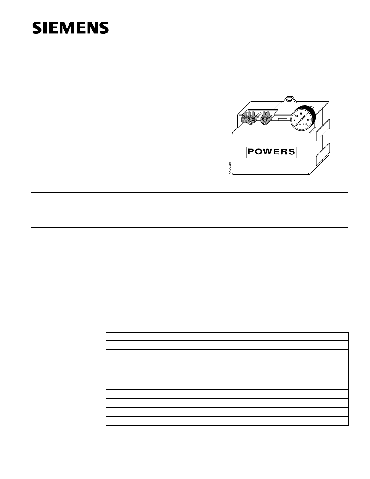
The RC 195 Multiple lnput Receiver-Controller is a pneumatic instrument which receives
one, two or three pneumatic inputs. It produces a pneumatic control signal based on the
net pneumatic input and the mechanical settings, such as setpoint, percent proportional
band and authority.
• Plug-in air connections make connecting, calibrating and servicing easy.
• lnternal restrictors provided for transmitter inputs.
• Stick-on scales for setpoint dial in standard transmitter ranges in both English and
metric units.
• Large, easy-to-read scales on all adjustments.
• Tamper–resistant cover.
The RC 195 Receiver-Controller is commonly used to control temperatures, humidity,
and pressures of mechanical equipment in commercial buildings, such as offices,
hospitals, universities and schools.
Product Numbers
195-0003 Multiple lnput Receiver-Controller with stick-on scales. See Table 2
195-066 Accessories*
195-067 Connector Kit
195-098, 195-099,
195-100
* Accessories must be ordered separately
195-130 Scale dispensing sheet kit English and Sl units DA and RA
142-0309 Plug (when gauge is not in use)
153-054 Receiver-Controller Calibration Slide Rule
144-022 Scale Conversion Card (Form)
Table 1.
Restrictor Kit
RC 195 Pressure Simulator
Siemens Industry, Inc.
Page 2

Technical Instructions RC 195 Multiple Input Receiver-Controller
Action: lnput #1 Direct Action (DA)
Percent proportional band adjustment range 2 to 20% for a 5 psi (34 kPa)
Mounting Surface
Document Number 155-036P25
November 7, 2005
Specifications
Operating
Physical
lnput #2 Reverse Action (RA)
Reset: Input #3 Direct reset relative to lnput #2
Reverse reset relative to lnput #1
Pneumatic inputs 3 to 15 psi (21 to 103 kPa)
Control output 0 psi (0 kPa) to supply pressure
Operating ambient temperature range 40 to 120°F (4 to 49°C)
SuppIy pressure
Operating 22 psi (152 kPa)
Maximum safe 30 psi (207 kPa)
control pressure change
Percent authority adjustment range 20 to 200%
Air consumption 60 scim (17 ml/s)
not including transmitters
Air Connections Barb fittings for 1/4-inch (6 mm) OD
plastic tubing
Two plug-in connectors are provided:
one for the three transmitter inputs and
one for supply and control lines.
1/8-inch NPT connection provided for
control pressure gauge
Case material Lexan, 20% glass filled
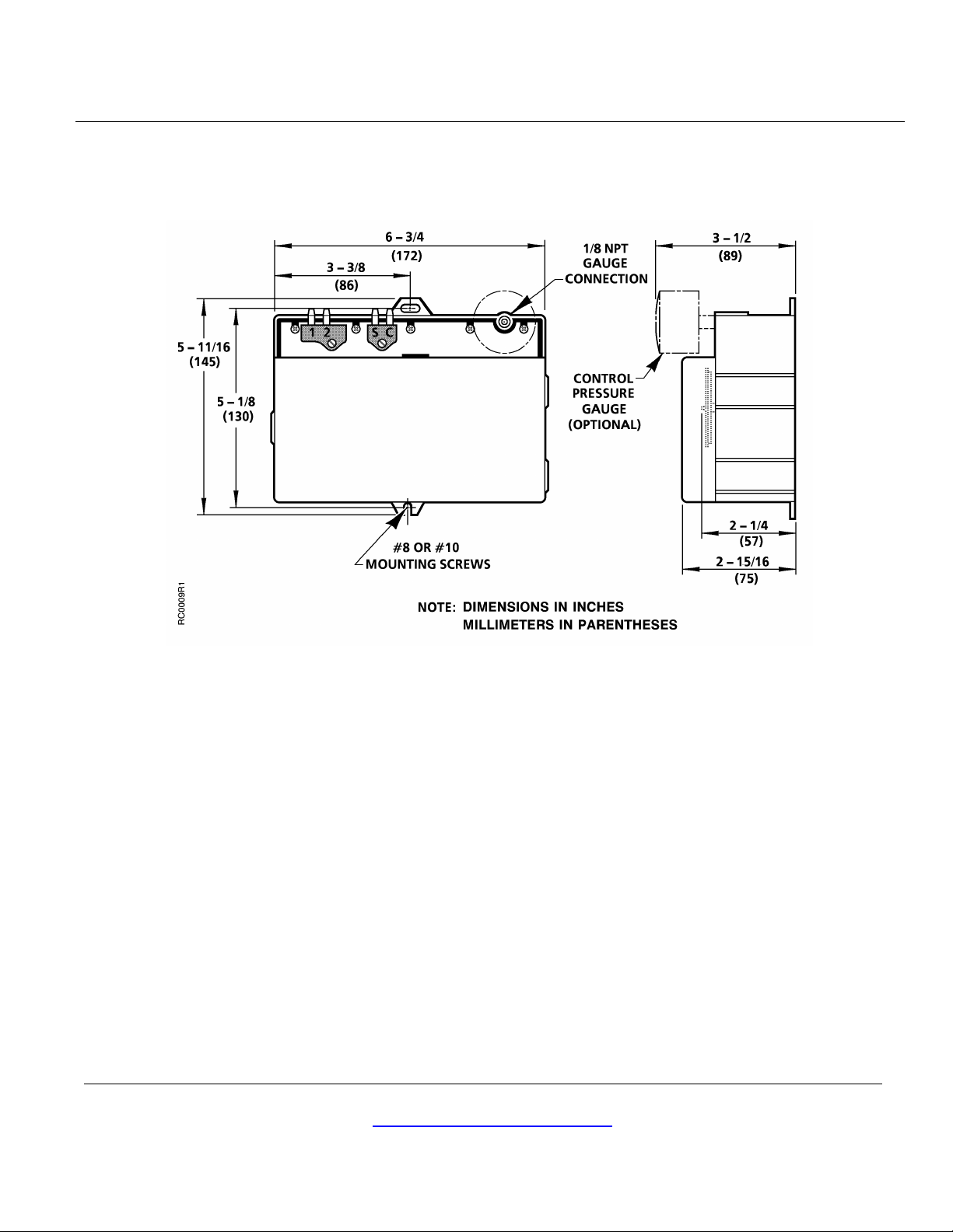
Dimensions See Figure 13
Weight 3.1 lb (1.4 Kg)
Operation
Inputs
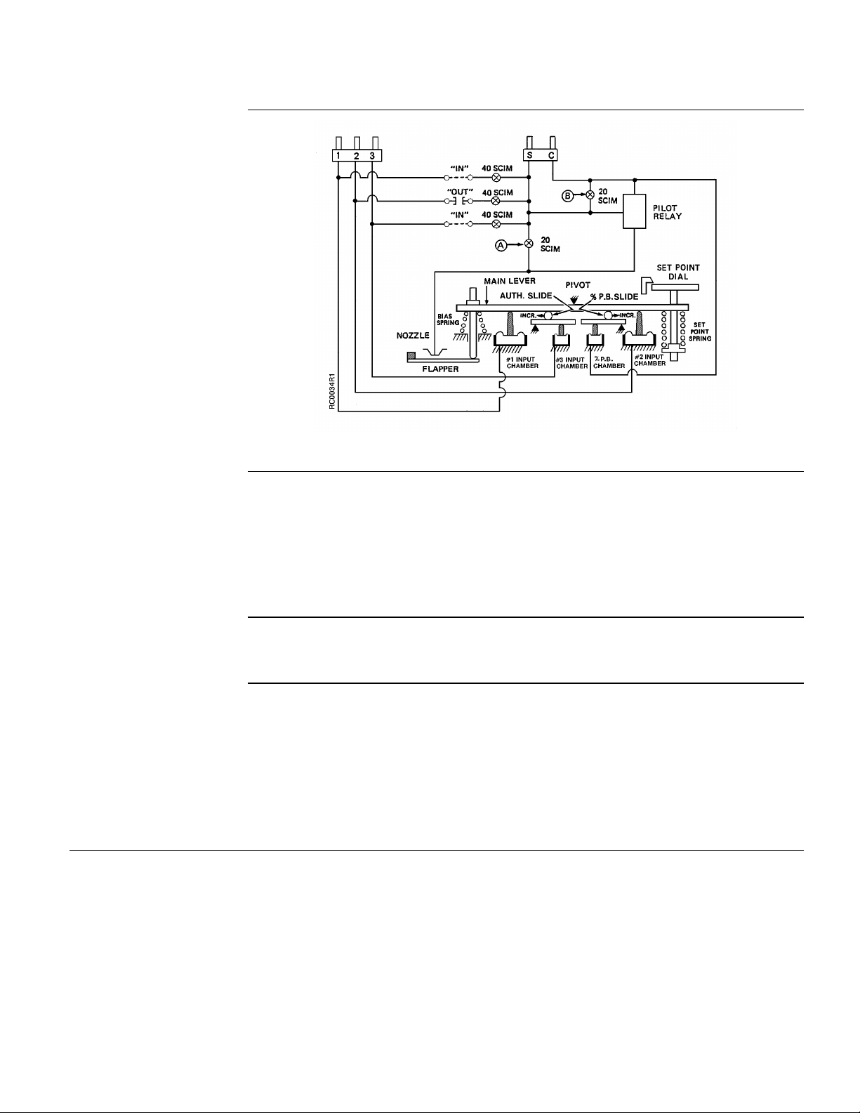
The control pressure depends upon the position of the main lever which is determined
by the sum of the forces acting upon it. On the left side of the pivot three forces act
against the lever: the bias spring, the #1 input pressure, and the #3 input pressure
acting through the authority slide.
On the right side of the pivot three forces act up against the lever; the control pressure
acting through the percent proportional band slide, the # 2 input pressure, and the
setpoint spring. See Figure 1.
When the net forces on each side of the pivot are equal, the lever is stationary and the
control pressure is constant. A change in any of the forces moves the main lever to a
new equilibrium position and provides a new control pressure. The inputs on the left side
of the pivot (#1 and #3) are direct acting and the input on the right side of the pivot (#2)
is reverse acting.
An internal 40 scim (11 ml/s) restrictor is furnished for each input. Each transmitter
restrictor must be switched "in" when an external restrictor is not being used. When any
input is not being used, its restrictor should be in the "out" position and the input
connection should be open to the atmosphere. Restrictor "A" provides nozzle pressure
and restrictor "B" minimizes hysteresis in the pilot relay. See Figure 1.
Page 2 Siemens Industry, Inc.
Page 3
RC 195 Multiple Input Receiver-Controller Technical Instructions
Document Number 155-036P25
November 7, 2005
Operation,
Continued
Figure 1. Multiple lnput Rece iver-Controller Schematic.
Percent Proportion al
Band
Authority
Authority Application
The pilot relay amplifies the nozzle pressure to provide the control pressure output.
Control pressure goes to the controlled device(s) as well as the percent proportional
band chamber to provide proportional feedback. For example, if the main lever is moved
up on the left side of the pivot, the flapper will move toward the nozzle to increase
control pressure. The increased pressure in the percent proportional band chamber will
move the main lever up on the right side of the pivot, moving the flapper away from the
nozzle until an equilibrium and a new control pressure are reached. The amount of
feedback is adjusted by moving the percent proportional band slide.
Authority is defined as the ratio of the change of the #1 or #2 input pressure to the
change of the #3 input pressure for the same control pressure change. The authority
slide provides a means of adjusting this ratio.
The RC 195 Receiver-Controller can be used as a one input (DA or RA) a two input (DA
or RA with reset), or a three input instrument (DA or RA with reset and control point
adjust).
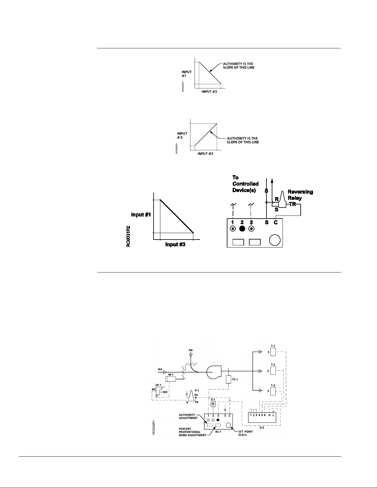
On reset applications, inputs 1 and 3 provide direct action with reverse reset (Figure 2),
and inputs 2 and 3 provide reverse action with direct reset (Figure 3). When other
combinations of action and reset are required (reverse action with reverse reset or direct
action with direct reset) use the combination of inputs that provide the proper reset
action and add a reversing relay in the control line of the RC 195 to change the action
(Figure 4).
Siemens Industry, Inc. Page 3
Page 4
Technical Instructions RC 195 Multiple Input Receiver-Controller
Document Number 155-036P25
November 7, 2005
Authority Application,
Continued
Figure 2. Authority for Reverse Reset.
Figure 3. Author ity for Direct Reset.
Figure 4. Receiver-Controller Using an RA Relay to Provide
Reset Action with Reverse Reset.
Description of
Application
Mixed Air Control - Reset From Zone – See Figure 5
Whenever the fan is running, EP Valve (EP-1) is energized to allow control of damper
motor (M-1). Multipurpose Relay (R-1) provides minimum percentage outdoor air.
Temperature Transmitter (TT-1) senses the mixed air temperature and sends a signal
to Receiver-Controller (RC-1). RC-1 modulates M-1 to maintain desired mixed air
temperature. Mixed air temperature setpoint is reset by the warmest zone thermostat
(T-1, T-2, T-3) through Signal Selector Relay (R-2). Positioning Switch (S-1) allows
manual reset of the mixed air setpoint at a remote location.
Figure 5. Typical Mixed Air Control Application.
Page 4 Siemens Industry, Inc.
Page 5
RC 195 Multiple Input Receiver-Controller Technical Instructions
Document Number 155-036P25
November 7, 2005
Installation
• The receiver-controller may be mounted in any position on any vertical surface using
two #8 or #10 screws. The integral mounting tabs are located on the top and bottom
General
of the case.
NOTE: Small vibrations such as those from an air handling unit will not affect the
operation of the instrument.
• Remove the cover by pulling it to the right; lifting, then pulling to the left and lifting.
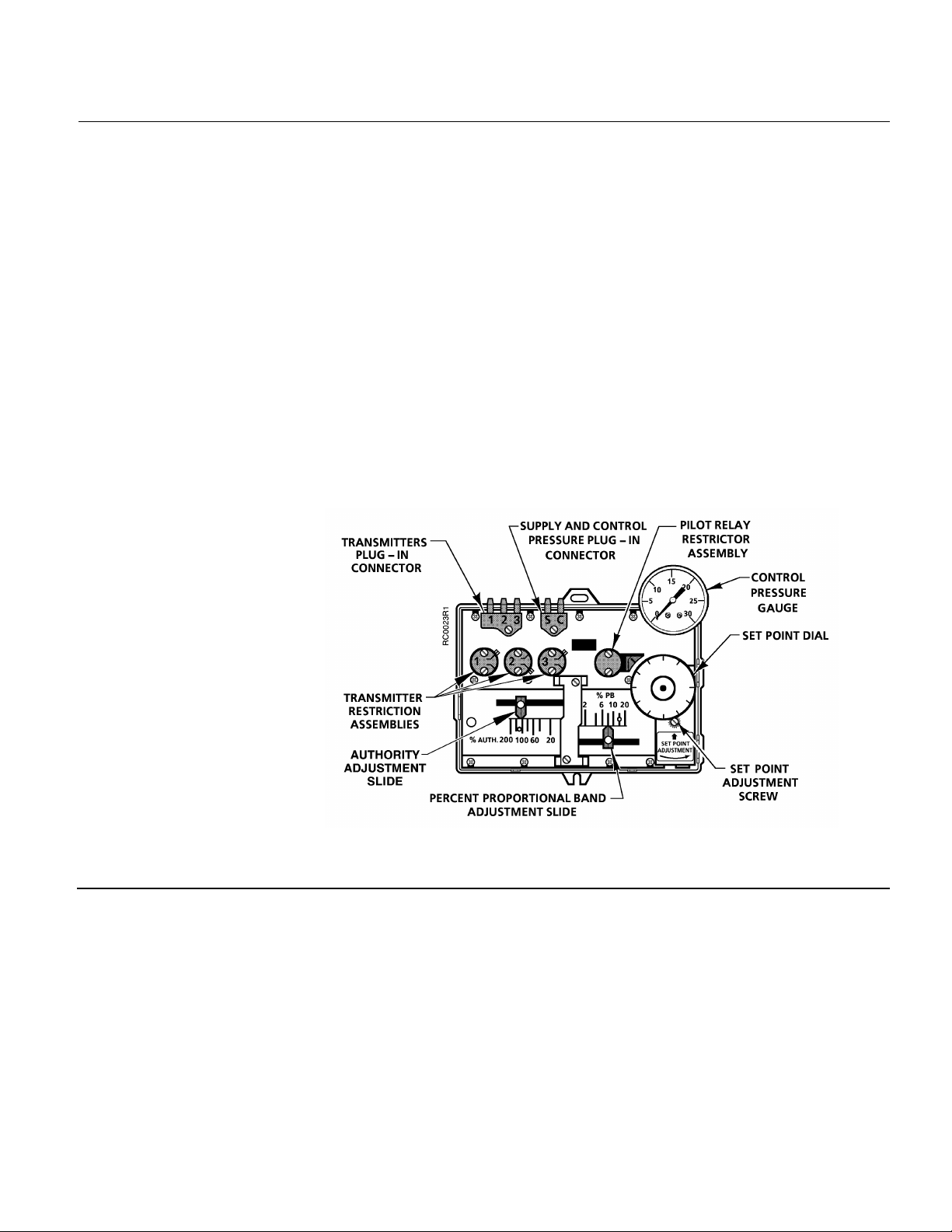
Remove the cover for access to the percent proportional band adjustment, the
authority slide, the setpoint dial, and setpoint adjustment screw.
• The setpoint dial comes with a 3-15 psi (21 to 103 kPa) scale. Place one of the
stick-on scales (Table 2) on the dial to match the primary transmitter range. Each
scale is marked DA or RA to match the required action of the receiver-controller.
• Check all the air connections, particularly those to the transmitters, to eliminate any
leaks. Even small leaks in the pneumatic lines to the transmitters will introduce large
errors.
• Check the supply pressure. The supply pressure must be a constant 22 psi
(152 kPa). If it is different or if a dual air supply is used, errors will be introduced into
the transmitted signals.
Figure 6. Multiple lnput Rece iver-Controller Connector, Restrictor,
and Adjustme n t L o cations.
Siemens Industry, Inc. Page 5
Page 6

Technical Instructions RC 195 Multiple Input Receiver-Controller
Document Number 155-036P25
November 7, 2005
Installation
Table 2. Scale Ranges.
Restrictors
English Scale
Identification
-40°F to 120°F A -40°C to 50°C
50°F to 100°F B 10°C to 38°C
80°F to 240°F C 26°C to 117°C
20% to 80% rh D 20% to 80% rh
0°F to 100°F E -18°C to 38°C
35°F to 135°F F 1°C to 58°C
0 IWG to 3 IWG G 0 Pa to 750 Pa
0 IWG to 15 lWG H 0 kPa to 3.75 kPa
0 IWG to 0.5 lWG J 0 Pa to 125 Pa
Blank 10 divisions
Blank 16 divisions
K (DA)
K (RA)
-0.05 IWG to 0.20 lWG L -12.5 Pa to 50 Pa
-0.5 IWG to 0.5 lWG M -125 Pa to 125 Pa
0 IWG to 10 lWG N 0 kPa to 2.5 kPa
Blank 20 divisions P Blank 15 divisions
0 psi to 50 psi R 0 kPa to 345 kPa
50°F to 150°F S 10°C to 66°C
40°F to 240°F T 4°C to 116°C
-40°F to 160°F V -40°C to 71°C
Restrictors are factory installed in all inputs of the receiver-controller. Restrictors are in
the "out" position as shipped from the factory. When an internal restrictor is required, the
restrictor must be moved to the "in" position. Use the following procedures when dialing
a new restrictor position:
Metric
Blank 9 divisions
Blank 11 divisions
• If the transmitter input line is connected to "1", use restrictor "1".
• If the transmitter input line is connected to "2", use restrictor "2".
1. Loosen both restrictor screws two full turns.
2. Move the restrictor tab back and forth between the full travel limits a minimum of
two times or until there is no sensation of drag against the lever. This will allow the
gasket to return to its proper position.
3. Tighten both screws with the restrictor lever fully in position against its stop. Do not
over tighten the screws. Screws should be tight enough to provide a good seal
without warping the restrictor assembly.
NOTE: When an Input is not being used, the restrictor should be in the "out" position
and the input connection should be open to atmosphere.
Page 6 Siemens Industry, Inc.
Page 7
RC 195 Multiple Input Receiver-Controller Technical Instructions
Document Number 155-036P25
November 7, 2005
Installation,
Continued
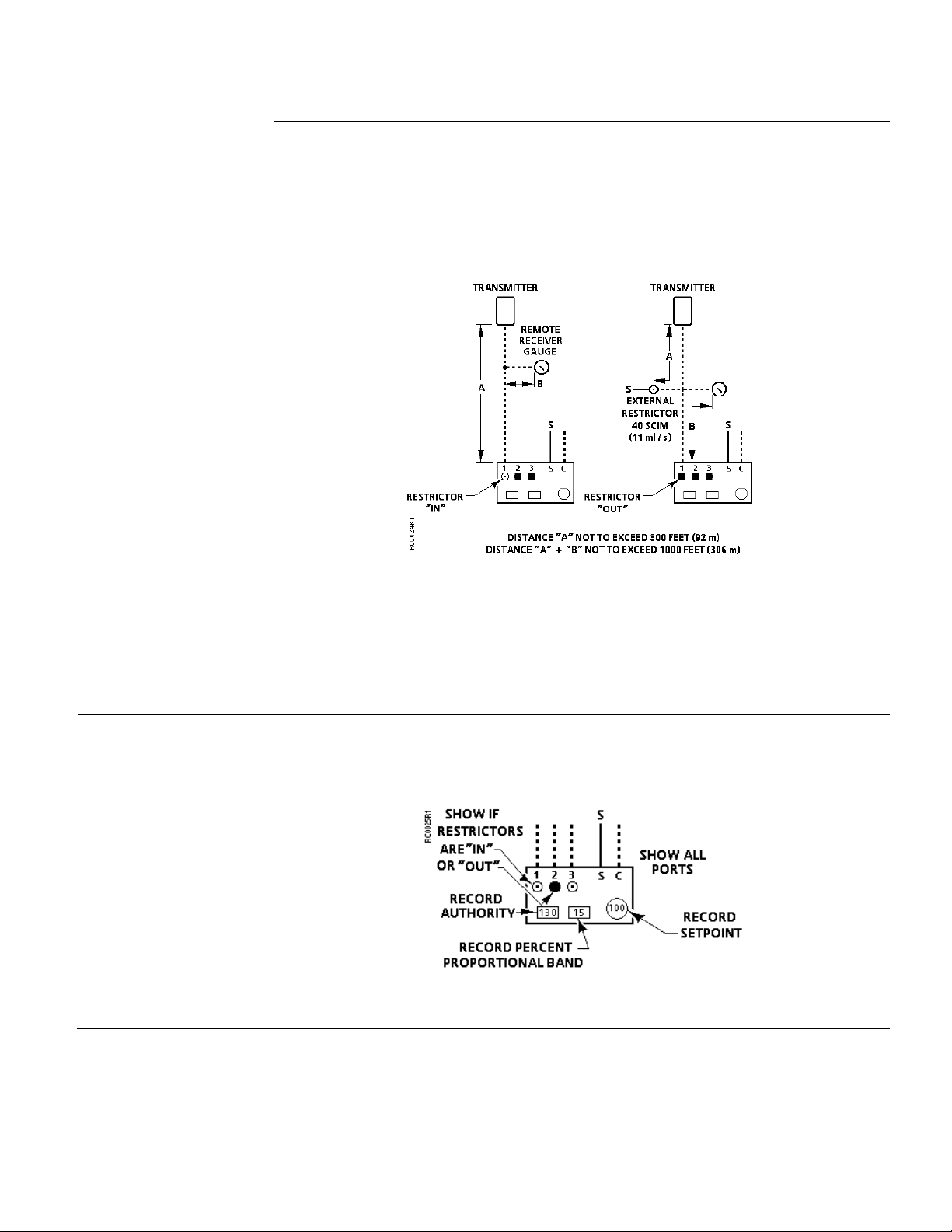
Figure 7 gives the maximum recommended distances for using the internal restrictor,
external restrictor, and remote gauges. Note that 300 feet (91.5 m) is the maximum
distance between air supply and the transmitter. If the distance is more than 300 feet
(91.5 m) between transmitter and receiver-controller, a remote air supply and external
restrictor must be used. If the maximum distances are exceeded, there will be excessive
pressure drops and time delays which will produce faulty indication and unsatisfactory
operation.
Figure 7. Maximum Distances for External Restrictors and Remote Gauges.
Calibration
Generally, 1/4–inch (6.4 mm) OD plastic tubing should be used for all the connections to
the plug-in air connectors. Larger size tubing will reduce the pressure drops, but will
increase time delays.
Conversely, smaller tubing will reduce time delays but will increase pressure drops.
Before making adjustments, several calculations are necessary. Steps 1, 2, 3 and 4 can
be completed before installation and are normally made by the field engineer with the
values noted on the control drawing. See Figure 8.
Figure 8. Control Drawing.
Siemens Industry, Inc. Page 7
Page 8

Technical Instructions RC 195 Multiple Input Receiver-Controller
Desired Throttling
×
Device (psi or kPa)
10°F
5 psi
Percent Proportion al Band Setting
5 psi (34 kPa) Spring
10 psi (69 kPa) Spring
°F (°C)
°F (°C)
4 8 12 4 8
12
(2)
(4)
(7)
(2)
(4)
(7)
Document Number 155-036P25
November 7, 2005
Calibration,
Step 1 Determine Percent Proportional Band setting using Formula A or Table 3.
Continued
Formula A
% P.B.=
* This is the control pressure change for which the percent proportional band scale is
designed.
Example 1:
5 psi (34.5 kPa) spring range
Desired throttling range 10°F (5.6 °C)
Transmitter span 100°F (56°C)
Using Formula A:
% P.B.=
Percent proportional board = 10%
For metric:
% P.B.=
Range (°F or °C)_ _
Controlling Transmitter Span
(°F or °C)
100°F
5.6°C
56°C
×
5 psi
34.5 kPa
×
34.5 kPa
*5 psi or 34.5 kPa
Spring Range Final
Controlled
× 100
× 100
× 100
Percent proportional board = 10%
Table 3. Percent Proportional Band Settings.
Transmitter
Span
°F (°C)
Desired Throttling Range
Desired Throttling Range
50 (28) 8% 16% - 4% 8% 12%
100 (56) 4% 8% 12% 2% 4% 6%
160 (89) 2.5% 5% 7% - 2.5% 3.8%
Page 8 Siemens Industry, Inc.
Page 9
RC 195 Multiple Input Receiver-Controller Technical Instructions
Example 2:
(120-80 + 10)
__160__
Document Number 155-036P25
November 7, 2005
Calibration,
Continued
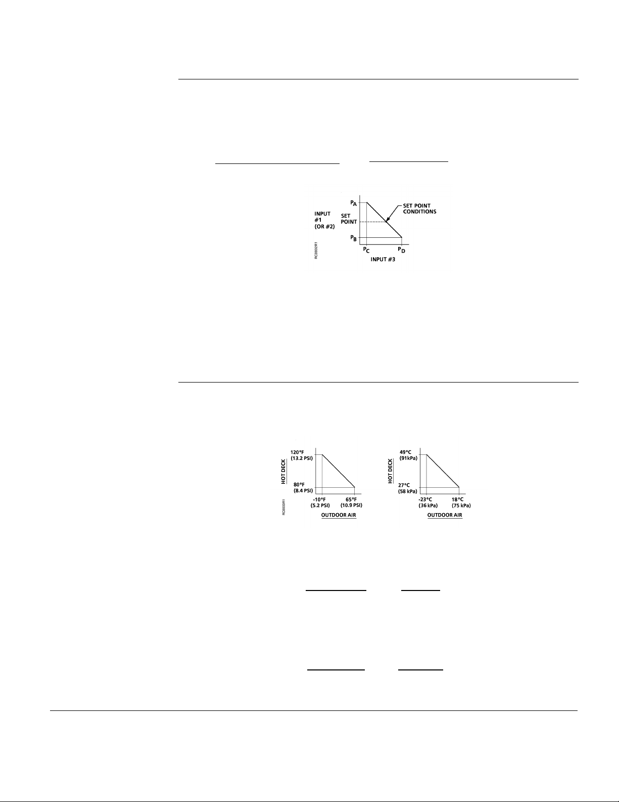
Step 2 Determine Percent Authority Setting using Formula B (Figure 9) or
graphically.
Using Formula B:
% Authority =
Change of input 1 or 2 + TR
Span of input 1 or 2
Span of input 3
×
Change of input 3
× 100
Figure 9. Graph of Percent Authority Formula.
Where:
Change of input 1 or 2 = PA - PB
Change of input 3 = PD - PC
T.R. = Throttling range
Assume a hot deck reset schedule as shown in Figure 10 and a 10°F (5.6°C) throttling
range.
Figure 10. Sample Percent A u th o rity.
°F:
Percent authority = 107%
°C:
% authority =
% authority =
100
(49-27) + 5.6
56
×
65-(-10)
___89___
×
18-(-23)
× 100
× 100
Percent authority = 107%
Siemens Industry, Inc. Page 9
Page 10

Technical Instructions RC 195 Multiple Input Receiver-Controller
Document Number 155-036P25
November 7, 2005
Calibration,
Continued
Calibration
Adjustments
Single Input
Step 3 Determine Setpoint Conditions.
For most applications it is necessary to select one point called "Setpoint Conditions" to
establish the value of all variables.
• For a single input receiver-controller, the setpoint condition equals the desired
control point. This is expressed in percent relative humidity, degrees Fahrenheit,
inches W.G., or metric units.
• For two and three input receiver-controllers the setpoint conditions equal the
midpoint of the usable portion of the schedule. See Figure 9. This is expressed in
percent RH, degrees Fahrenheit, inches W.G., or metric units.
Step 4 Record data from Steps 1, 2, and 3 on Control Drawing.
Figures 5 and Figure 8 show how the values of percent proportional band, the percent
authority, and setpoint should be recorded.
NOTE: Whenever the proportional band is changed, the setpoint dial must be
recalibrated.
1. Set proportional band pointer to value shown on the control drawing.
2. Apply setpoint pressure to selected input (#1/DA or #2/RA) and with a screwdriver
turn the setpoint adjustment screw until control pressure reaches 8 psi (55 kPa) or
midpoint pressure of the spring range of actuator.
3. Calibrate setpoint dial by pulling it up, turning it to agree with the transmitter input,
and then releasing it.
4. Turn the setpoint adjustment screw until dial agrees with control drawing.
Two or Three Inputs
1. Attach the RC 195 Simulator by means of the plug-in connector. See Technical
lnstructions RC 195-3 (Document Number 155-103P25) for details.
2. Proportional band. Move the pointer to the desired setting on the proportional band
scale of the receiver-controller.
3. Authority. When input three is used, move the pointer to the desired setting on the
authority scale of the receiver-controller.
4. Simulate setpoint conditions. Adjust the knobs on the simulator so that all the
pneumatic inputs are at their setpoint condition.
5. Setpoint. Turn the setpoint adjustment screw of the receiver-controller to obtain the
desired control pressure. Pull the setpoint dial up, turn it to agree with the control
schematic and then release it.
6. Check operation. Pneumatic inputs corresponding to both ends of the reset
schedule can be simulated to ensure that the receiver controller is in calibration
throughout its entire range. Minor variations of 2 to 3 psi (14 to 21 kPa) in the
control pressure are normal.
Page 10 Siemens Industry, Inc.
Page 11

RC 195 Multiple Input Receiver-Controller Technical Instructions
Complaint
Check
Probable Cause
Corrective Action
Document Number 155-036P25
November 7, 2005
Troubleshooting
Control pressure
stays at
approximately zero
Control pressure
stays at
approximately supply
pressure
Before troubleshooting the operation of the RC 195 Multiple lnput Receiver-Controller,
verify the following:
1. Supply pressure at the unit is 22 psi (152 kPa).
2. Transmitter input being used is between 3 and 15 psi (21 to 103 kPa).
3. Only one restrictor supplies the transmitter.
4. Transmitter calibration is correct.
Table 4. Troubleshooting Guide.
Transmitter sensing medium
Rotate setpoint
adjustment screw
counterclockwise
Rotate setpoint
adjustment screw
clockwise
Pressure increases
Pressure remains
unchanged
Pressure decreases
Pressure remains
unchanged
which is above (RA) or below
(DA) the proportional band
Receiver controller out of
calibration
Plugged pilot relay restrictors Replace Pilot Relay
Receiver-Controller is defective Replace Receiver
Transmitter sensing medium
which is above (DA) or below
(RA) the proportional band
Receiver-Controller out of
calibration
Receiver-Controller is defective Replace Receiver-
None
Recalibrate
Restrictors
Controller
None
Recalibrate
Controller
Siemens Industry, Inc. Page 11
Page 12
Technical Instructions RC 195 Multiple Input Receiver-Controller
Document Number 155-036P25
November 7, 2005
Troubleshooting, Continued
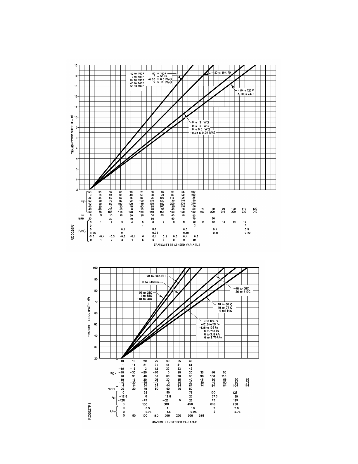
Figure 11. Output Pressure/Transmitter Range Relationship In English Units.
Figure 12. Output Pressure/Transmitter Range Relationship In English Units.
Page 12 Siemens Industry, Inc.
Page 13
RC 195 Multiple Input Receiver-Controller Technical Instructions
Siemens Industry, Inc.
Your feedback is im port ant to us. If you have
Document No. 155-036P25
Document Number 155-036P25
November 7, 2005
Dimensions
Figure 13. Dimensions.
Information in this publication is based on current specifications. The company reserves the right to m ake changes in specifi c ations and models as
design improvements are introduced. Powers is a registered trademark of Siemens I ndustry, Inc. Product or c ompany names mentioned herein
may be the trademarks of their respective owners. © 2005 Siemens Industry, Inc.
Building Technologies Divis i on
1000 Deerfield Parkway
Buffalo Grove, IL 60089
+ 1 847-215-1000
comments about this document, please send them to
Printed in the USA
Page 13
 Loading...