

Siemens RBC,MBC Installation Instructions Manual
Installation Instructions
Document No. 586-797
August 25, 2005
Modular Building Controller (MBC)
Remote Building Controller (RBC)
Backplane and Cable Kit
Product Description
Kit provides MBC or RBC Replacement Backplane with
connection for 24 VAC, Class 1 power when installed in
rd
party cabinet meeting NEMA Type 1.
3
CAUTION:
Use of a backplane outside of NEMA Type 1
or controlled environment relatively free of
contaminants voids all UL, CSA, and FCC
approvals, as well as European EMC and
LVD compliance. All listings and
declarations are responsibility of cabinet
manufacturer or system integrator.
Product Numbers
545-735 MBC/RBC Backplane 24Vac Cable Kit
includes low voltage power cable, 10A circuit
breaker, MOVs and terminating hardware for
use with any Replacement Backplanes without
MBC/RBC enclosure.
545-077 Replacement Backplane—MBC-24 See
Installation Instructions (545-411)
545-078 Replacement Backplane—MBC-40
See Installation Instructions (545-411)
545-274 Replacement Backplane—RBC See
Installation Instructions (545-261)
Danger/Warning Notations
DANGER:
WARNING:
CAUTION:
Electric shock, death, or
severe property damage may
occur if you do not follow a
procedure as specified.
Personal injury or property
damage may occur if you do
not follow a procedure as
specified.
Equipment damage or loss of
data may occur if you do not
follow the procedures as
specified.
Required Tools
• Phillips #2 screwdriver
• 1/4-inch nut driver
• 1/8-inch standard screwdriver
Expected Installation Time
10 minutes for each backplane.
Prerequisites
WARNING:
Only a qualified electrician or authorized
Siemens Building Technologies
representative should perform installation.
•
All MBC-40, MBC-24 or RBC Backplanes are not
yet mounted to cabinet chassis.
•
Class 1, 115/230V to 24V AC Transformer is
mounted in cabinet and sized for total power of all
backplanes per requirements in Table 1.
•
Cabinet is connected to an approved building
earth ground using dedicated 3
•
Cabinet has provisions for low impedance ground
from all backplanes to the cabinet earth ground
connection point.
Cabinet has mounting features and hardware for
the backplane ca• pable of minimum 250lb. vertical
sheer strength.
•
Multiple cabinets are connected to same or
bonded building earth groun
installed between cabinets.
Table r S ments
1. Transforme
Ba e
ckplan
Type sforme
MBC-24 120
M 200 BC-40
RBC 80
Note each Backplane circuit breaker is 10A.
izing Require
Minimum VA
Tran r
rd
wire.
d or optical isolation
Item Number: 586-797 Rev. 010
Page 1 of 2
Document No. 586-797
Installation Instructions
August 25, 2005
Instructions
I innstall g the Backplane
WARNING:
Before securing, ensure no wires are caught
or pinched behind the backplane.
Insert the MBC-24 or MBC-40 backplane conne
1. ctor
through the rectangular cutout on the right side of
backplane.
Snap in place, as shown in (Error!
t found.1). (RBC already Reference source no
installed.)
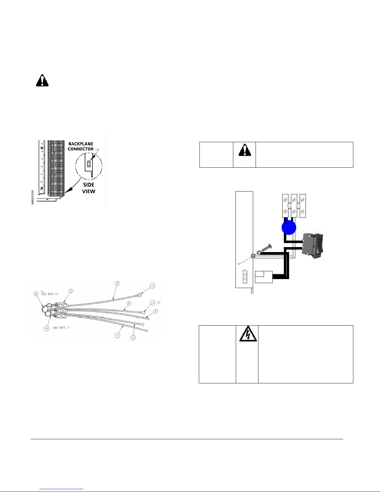
Figure 1. MBC-24 Backplane connector.
2. Using ¼ in. (6.35mm) hardware provided by the
cabinet manufacturer mount the backplanes:
•
MBC-24, 7-1/2 x 16-15/16 in (190mm x 430mm)
MBC-40, 7-1/2 x 26-15/1• 6 in (190mm x 684mm)
•
RBC, 7-1/2 x 11-3/4 in (190mm x 298mm) th
places bottom centered
Installing the Line Voltage Varistors
the
ree
4. Attach ¼ quick connect (13) on black wire (10) to
transformer and (11) to Line voltage not greater than
240VAC typical with the wire nut.
Installing the Low Voltage Cable
1. Provide a 1-1/8 (28.5mm) x 9/16 in. (13.5mm) cutout
for the circuit breaker or remove tape backing and
apply to clean, dry surface.
2. Secure terminal to cabinet with sheet metal screws.
3. Using Phillips screw with washer secure the ring
terminals on the neutral wires to the backplane.
CAUTION:
4. Screw 24VAC Hot and Neutral wires into terminal.
5. Plug the low voltage power cable into backplane.
Where multiple backplanes are
powered by one transformer
ensure H N polarity is observed.
H N
Figure 3. Low Voltage Power Cable Assembly.
Completing the Installation
1. Apply Shutdown label adjacent to circuit breaker.
DANGER:
ure 2. Line Voltage Varistor AssFig embly
1. Place insulator under terminal strip (3) and secure to
cabinet with sheet metal screws.
2. Attach ring (12) on green/yellow wire (7) to cabine
t
approved building earth ground point.
3. Attach ¼ quick connect (13) on white wire (8) to
The installation is now complete
transformer and (9) to Neutral with the wire nut.
Information in this publication is based on current specifications. The company reserves the right to make changes in specifications and models as
design improvements are introduced. © 2005 Siemens Building Technologies, Inc.
Siemens Building Technologies, Inc.
1000 Deerfield Parkway
Buffalo Grove, IL 60089-4513
U.S.A.
Your feedback is important to us. If you have
comments about this document, please send
them to technical.editor@siemens.com
The circuit breaker may not
disconnect all high voltage I/O
modules.
Incorporate a readily accessible
disconnect device for high
voltage I/O modules into the
wiring outside the backplane.
Document No. 586-797
Printed in the U.S.A.
Page 2 of 2
 Loading...