

Page 1

NOTIFICATION OF MANUAL STATUS
RB-6 L-801A (Airport) Rotating Beacon (Export) is now sold by Halibrite. Use manual 96A0221 only
for old equipment in the field. Discard this notification page before sending manual.
Page 2
RB-6 L-801A (Airport)
Rotating Beacon (Export)
Document No. 96A0221
Issued: February 6, 1998
Rev. B: May 16, 2001
Manufactured to FAA Specification
AC 150/5345-12C
Copyright 2001 by Siemens Airfield Solutions, Incorporated. All rights reserved.
Page 3

RB-6 L-801A (Airport) Rotating Beacon (Export) Record of Changes
Record of Changes
Page Rev Description EC No. Checked Approved Date
A Released manual.
All B Changed to new title page. Changed ADB to
Siemens Airfield Solutions.
3250 KJ VP 2/6/98
00696 KJ WT 5/16/01
2001 Siemens Airfield Solutions, Incorporated
All rights reserved Issued 5/01
96A0221B Page ii
Page 4

RB-6 L-801A (Airport) Rotating Beacon (Export) Table of Contents
Table of Contents
Record of Changes.......................................................................................................................................................................ii
Table of Contents........................................................................................................................................................................iii
Warranties...................................................................................................................................................................................vi
Safety
Description
1. Introduction...........................................................................................1-1
2. Safety Symbols .....................................................................................1-1
3. Qualified Personnel...............................................................................1-2
4. Intended Use .........................................................................................1-2
5. Installation.............................................................................................1-3
6. Operation...............................................................................................1-3
7. Action in the Event of a System
or Component Malfunction...................................................................1-4
8. Maintenance and Repair........................................................................1-4
1. Introduction...........................................................................................2-1
2. RB-6 Beacon Assemblies......................................................................2-3
Head Assembly .................................................................................2-3
Hub and Shaft Assembly...................................................................2-3
Box Assembly...................................................................................2-3
Motor and Drive Assembly...............................................................2-3
3. Options..................................................................................................2-3
Optional Obstruction Light...............................................................2-3
Optional Heater Assembly................................................................2-5
Optional Mounting Bases..................................................................2-6
Optional Photocell Assembly............................................................2-8
4. Theory of Operation..............................................................................2-8
RB-6 Rotating Beacon Operations ................................................2-8
Optional Heater Assembly Operations..........................................2-8
Optional Photocell Assembly Operations......................................2-9
Optional Obstruction Light Operations.........................................2-9
5. RB-6 Rotating Beacon: Required Equipment.......................................2-9
6. Specifications......................................................................................2-10
Input................................................................................................2-10
Beacon Wattage ..............................................................................2-10
Lenses..............................................................................................2-10
Rated Lamp Life .............................................................................2-10
Lamp Wattage.................................................................................2-10
Beam Intensity ................................................................................2-11
Rotation Speed................................................................................2-11
Heater..............................................................................................2-11
Environmental Operating Conditions..............................................2-11
Weight.............................................................................................2-11
Dimensions......................................................................................2-12
Clearance for Rotation ....................................................................2-12
Mounting Dimensions.....................................................................2-12
2001 Siemens Airfield Solutions, Incorporated
All rights reserved Issued 5/01
96A0221B Page iii
Page 5

RB-6 L-801A (Airport) Rotating Beacon (Export) Table of Contents
Installation
Maintenance
Troubleshooting
Parts
Wiring Schematics
1. Introduction...........................................................................................3-1
2. Unpacking.............................................................................................3-1
3. RB-6 Beacon Installation......................................................................3-1
Mounting ..........................................................................................3-1
Wiring ...............................................................................................3-2
Optional Heater Wiring.....................................................................3-2
Angle Adjustment.............................................................................3-2
Export Beacon Installation Requirement ..........................................3-4
1. Introduction...........................................................................................4-1
2. Maintenance Schedule ..........................................................................4-1
3. Maintenance Procedures .......................................................................4-2
Replacing Lamp................................................................................4-2
Adjusting Lamp Beam ......................................................................4-2
Replacing Brushes and Brush Brackets ............................................4-3
Cleaning Lenses................................................................................4-6
Cleaning Head Assembly..................................................................4-6
Cleaning Slip Rings and Brushes......................................................4-6
Lubricating Parts...............................................................................4-7
1. Introduction...........................................................................................5-1
2. Troubleshooting Procedures .................................................................5-1
1. Introduction.........................................................................................6-1
2. Using the Illustrated Parts List............................................................6-1
3. RB-6 Rotating Beacon Final Assembly Parts List..............................6-2
4. Head Assembly (Single Head) Parts List............................................6-4
5. Box Assembly Parts List.....................................................................6-6
6. Motor Assembly Parts List..................................................................6-8
7. Brush Block Assembly Parts List........................................................6-9
8. Photocell Contractor Parts List .........................................................6-11
9. Heater Assembly Parts List...............................................................6-13
10. Reflector Assembly Parts List...........................................................6-15
11. Obstruction Light and Relay Parts List.............................................6-17
12. Optional Assemblies Parts List.........................................................6-19
1. Introduction...........................................................................................7-1
2. Wiring Schematics................................................................................7-1
RB-6 with Optional Heater Wiring...................................................7-1
Optional Photocell Assembly Wiring ...............................................7-3
2001 Siemens Airfield Solutions, Incorporated
All rights reserved Issued 5/01
96A0221B Page iv
Page 6

RB-6 L-801A (Airport) Rotating Beacon (Export) Table of Contents
List of Figures
List of Tables
Figure 2-1. RB-6 Rotating Beacon............................................................2-2
Figure 2-2. RB-6 Final Assembly with Optional
Obstruction Light Wiring.......................................................2-4
Figure 2-3. Optional Heater Assembly Wiring.........................................2-5
Figure 2-4. Optional Pole Mounting Adapter ...........................................2-6
Figure 2-5. Optional Roof Mounting Assembly .......................................2-7
Figure 2-6. Mounting Holes....................................................................2-12
Figure 3-1. Adjusting Beacon Angle ........................................................3-3
Figure 4-1. Brush Block Assembly...........................................................4-3
Figure 4-2. Pre-Bending New Brush Brackets..........................................4-5
Figure 6-1. RB-6 Rotating Beacon Final Assembly (Export Version) ....6-3
Figure 6-2. Head Assembly (Single Head)...............................................6-5
Figure 6-3. Box Assembly........................................................................6-7
Figure 6-4. Motor Assembly.....................................................................6-8
Figure 6-5. Brush Block Assembly.........................................................6-10
Figure 6-6. Photocell Contactor Assembly.............................................6-12
Figure 6-7. Heater Assembly ..................................................................6-14
Figure 6-8. Reflector Assembly..............................................................6-16
Figure 6-9. Obstruction Light .................................................................6-18
Figure 7-1. RB-6 Beacon with Optional Heater Wiring Schematic..........7-2
Figure 7-2. Optional Photocell Assembly Wiring Schematic...................7-3
Table 2-1. Required Equipment Supplied.................................................2-9
Table 2-2. Required Equipment Not Supplied........................................2-10
Table 4-1. RB-6 Rotating Beacon (Export Version) Maintenance...........4-1
2001 Siemens Airfield Solutions, Incorporated
All rights reserved Issued 5/01
96A0221B Page v
Page 7

RB-6 L-801A (Airport) Rotating Beacon (Export) Warranties
Products of Siemens Airfield Solutions manufacture are guaranteed against
Warranties
Disclaimers
mechanical, electrical, and physical defects (excluding lamps) for a period
of one year from the date of installation or a maximum of two years from
the date of shipment and are guaranteed to be merchantable and fit for the
ordinary purposes for which such products are made.
Siemens Airfield Solutions will correct by repair or replacement, at its
option, equipment or parts which fail because of mechanical, electrical or
physical defects, provided that the goods have been properly handled and
stored prior to installation, properly installed and properly operated after
installation, and provided further that Buyer gives Siemens Airfield
Solutions written notice of such defects after delivery of the goods to
Buyer.
Siemens Airfield Solutions reserves the right to examine goods upon which
a claim is made. Said goods must be presented in the same condition as
when the defect therein was discovered. Siemens Airfield Solutions furthers
reserves the right to require the return of such goods to establish any claim.
Siemens Airfield Solutions’s obligation under this guarantee is limited to
making repair or replacement within a reasonable time after receipt of such
written notice and does not include any other costs such as the cost of
removal of defective part, installation of repaired product, labor or
consequential damages of any kind, the exclusive remedy being to require
such new parts to be furnished.
Siemens Airfield Solutions’s liability under no circumstances will exceed
the contract price of goods claimed to be defective. Any returns under this
guarantee are to be on a transportation charges prepaid basis. For products
not manufactured by, but sold by Siemens Airfield Solutions, warranty is
limited to that extended by the original manufacturer.
This is Siemens Airfield Solutions’s sole guarantee and warranty with
respect to the goods; there are no express warranties or warranties of fitness
for any particular purpose or any implied warranties of fitness for any
particular purpose or any implied warranties other than those made
expressly herein. All such warranties being expressly disclaimed.
This manual could contain technical inaccuracies or typographical errors.
Siemens Airfield Solutions reserves the right to revise this manual from
time to time in the contents thereof without obligation of Siemens Airfield
Solutions to notify any person of such revision or change.
Details and values given in this manual are average values and have been
compiled with care. They are not binding, however, and Siemens Airfield
Solutions disclaims any liability for damages or detriments suffered as a
result of reliance on the information given herein or the use of products,
processes or equipment to which this manual refers. No warranty is made
that the use of the information or of the products, processes or equipment to
which this manual refers will not infringe any third party’s patents or rights.
The information given does not release the buyer from making their own
experiments and tests.
2001 Siemens Airfield Solutions, Incorporated
All rights reserved Issued 5/01
96A0221B Page vi
Page 8
RB-6 L-801A (Airport) Rotating Beacon (Export) Safety
Section 1
Safety
1. Introduction
2. Safety Symbols
This section contains general safety instructions for using your Siemens
Airfield Solutions equipment. Some safety instructions may not apply to
the equipment in this manual. Task- and equipment-specific warnings are
included in other sections of this manual where appropriate. Note all
warnings and follow all instructions carefully. Failure to do so may result
in personal injury, death, or property damage.
To use this equipment safely,
• refer to the FAA Advisory Circular AC 150/5340-26, Maintenance of
Airport Visual Aids Facilities, for instructions on safety precautions.
• observe all safety regulations. To avoid injuries, always remove power
prior to making any wire connections and touching any parts. Refer to
FAA Advisory Circular AC 150/5340-26.
• read and become familiar with the general safety instructions provided
in this section of the manual before installing, operating, maintainin g,
or repairing this equipment.
• read and carefully follow the instructions given throughout this manual
for performing specific tasks and working with specific equipment.
• store this manual within easy reach of personnel installing, operating,
maintaining, or repairing this equipment.
• follow all applicable safety procedures required by your company,
industry standards, and government or other regulatory agencies.
• obtain and read Material Safety Data Sheets (MSDS) for all materials
used.
Become familiar with the safety symbols presented in this section. These
symbols will alert you to safety hazards and conditions that may result in
personal injury, death, or property and equipment damage.
WARNING: Failure to observe this warning may result in
personal injury, death, or equipment damage.
WARNING: Risk of electrical shock. Failure to observe this
warning may result in personal injury, death, or equipment
damage.
2001 Siemens Airfield Solutions, Incorporated
All rights reserved Issued 5/01
96A0221B Page 1-1
Page 9
RB-6 L-801A (Airport) Rotating Beacon (Export) Safety
2. Safety Symbols (contd.)
3. Qualified Personnel
4. Intended Use
The term qualified personnel is defined here as individuals who thoroughly
understand the equipment and its safe operation, maintenance, and repair.
Qualified personnel are physically capable of performing the required tasks,
familiar with all relevant safety rules and regulations and have been trained
to safely install, operate, maintain, and repair the equipment. It is the
responsibility of the company operating this equipment to see that its
personnel meet these requirements.
Siemens Airfield Solutions cannot be responsible for injuries or damages
resulting from nonstandard, unintended applications of its equipment. This
equipment is designed and intended only for the purpose described in this
manual. Uses not described in this manual are considered unintended uses
and may result in serious personal injury, death, or property damage.
Unintended uses may result from taking the following actions:
• making changes to equipment that have not been recommended or
• failing to make sure that auxiliary equipment complies with approval
• usin g materials or auxiliary equipment that are inappropriate or
• allowing unqualified personnel to perform any task
WARNING: Disconnect equipment from line voltage. Failure
to observe this warning may result in personal injury, death, or
equipment damage.
WARNING: Wear safety goggles. Failure to observe may
result in serious injury.
CAUTION: Failure to observe may result in equipment
damage.
WARNING: Use of this equipment in ways other than
described in this manual may result in personal injury, death, or
property and equipment damage. Use this equipment only as
described in this manual.
described in this manual or using parts that are not genuine Siemens
Airfield Solutions replacement parts
agency requirements, local codes, and all applicable safety standards
incompatible with your Siemens Airfield Solutions equipment
2001 Siemens Airfield Solutions, Incorporated
All rights reserved Issued 5/01
96A0221B Page 1-2
Page 10
RB-6 L-801A (Airport) Rotating Beacon (Export) Safety
5. Installation
6. Operation
Read the installation section of all system component manuals before
installing your equipment. A thorough understanding of system
components and their requirements will help you install the system safely
and efficiently.
WARNING: Failure to follow these safety procedures can
result in personal injury or death.
• Allow only qualified personnel to install Siemens Airfield Solutions
and auxiliary equipment. Use only approved equipment. Using
unapproved equipment in an approved system may void agency
approvals.
• Make sure all equipment is rated and approved for the environment in
which you are using it.
• Follow all instructions for installing components and accessories.
• Install all electrical connections to local code.
• Use only electrical wire of sufficient gauge and insulation to handle the
rated current demand. All wiring must meet local codes.
• Route electrical wiring along a protected path. Make sure they will not
be damaged by moving equipment.
• Protect components from damage, wear, and harsh environment
conditions.
• Allow ample room for maintenance, panel accessibility, and cover
removal.
• Protect equipment with safety devices as specified by applicable safety
regulations.
• If safety devices must be removed for installation, install them
immediately after the work is completed and check them for proper
functioning.
Only qualified personnel, physically capable of operating the equipment
and with no impairments in their judgment or reaction times, should operate
this equipment.
Read all system component manuals before operating this equipment. A
thorough understanding of system components and their operation will help
you operate the system safely and efficiently.
2001 Siemens Airfield Solutions, Incorporated
All rights reserved Issued 5/01
96A0221B Page 1-3
Page 11

RB-6 L-801A (Airport) Rotating Beacon (Export) Safety
6. Operation (contd.)
7. Action in the Event of a
System or Component
Malfunction
8. Maintenance and Repair
• Before starting this equipment, check all safety interlocks, fire-
detection systems, and protective devices such as panels and covers.
Make sure all devices are fully functional. Do not operate the system if
these devices are not working properly. Do not deactivate or bypass
automatic safety interlocks or locked-out electrical disconnects or
pneumatic valves.
• Never operate equipment with a known malfunction.
• Do not attempt to operate or service electrical equipment if standing
water is present.
• Use this equipment only in the environments for which it is rated. Do
not operate this equipment in humid, flammable, or explosive
environments unless it has been rated for safe operation in these
environments.
• Never touch exposed electrical connections on equipment while the
power is ON.
Do not operate a system that contains malfunctioning components. If a
component malfunctions, turn the system OFF immediately.
• Disconnect and lock out electrical power.
• Allow only qualified personnel to make repairs. Repair or replace the
malfunctioning component according to instructions provided in its
manual.
Allow only qualified personnel to perform maintenance, troubleshooting,
and repair tasks. Only persons who are properly trained and familiar with
Siemens Airfield Solutions equipment are permitted to service this
equipment.
• Always use safety devices when working on this equipment.
• Follow the recommended maintenance procedures in your equipment
manuals.
• Do not service or adjust any equipment unless another person trained in
first aid and CPR is present.
• Connect all disconnected equipment ground cables and wires after
servicing equipment. Ground all conductive equipment.
• Use only approved Siemens Airfield Solutions replacement parts.
Using unapproved parts or making unapproved modifications to
equipment may void agency approvals and create safety hazards.
2001 Siemens Airfield Solutions, Incorporated
All rights reserved Issued 5/01
96A0221B Page 1-4
Page 12

RB-6 L-801A (Airport) Rotating Beacon (Export) Safety
8. Maintenance and Repair
(contd.)
• Check interlock systems periodically to ensure their effectiveness.
• Do not attempt to service electrical equipment if standing water is
present. Use caution when servicing electrical equipment in a highhumidity environment.
• Use tools with insulated handles when working with electrical
equipment.
2001 Siemens Airfield Solutions, Incorporated
All rights reserved Issued 5/01
96A0221B Page 1-5
Page 13

RB-6 L-801A (Airport) Rotating Beacon (Export) Description
Section 2
Description
1. Introduction
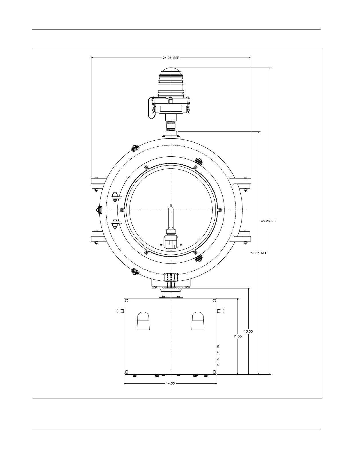
See Figure 2-1. This section describes the Siemens Airfield Solutions RB-6
rotating beacon (Export Version). The RB-6 is manufactured to
specification AC 150/5345-12C.
The RB-6 all-weather rotating beacon (Export Version) consists of a
rotating unit on which are mounted a cast-aluminum housing containing
1000-W PAR64 spot quartz lamps, and a motor box.
An electrical connection is provided on the terminal block, located in the
motor box, for a light or alarm to indicate a lamp failure. The rotating unit
is mounted on a vertical shaft that turns at 12.5 revolutions per minute,
resulting in an output of 24-30 flashes per minute, alternately white and
green.
2001 Siemens Airfield Solutions, Incorporated
All rights reserved Issued 5/01
96A0221B Page 2-1
Page 14
RB-6 L-801A (Airport) Rotating Beacon (Export) Description
Figure 2-1. RB-6 Rotating Beacon
2001 Siemens Airfield Solutions, Incorporated
All rights reserved Issued 5/01
96A0221B Page 2-2
Page 15

RB-6 L-801A (Airport) Rotating Beacon (Export) Description
2. RB-6 Beacon Assemblies
Head Assembly
Hub and Shaft Assembly
Box Assembly
Motor and Drive Assembly
3. Options
Optional Obstruction Light
The RB-6 beacon consists of the following assemblies: a head assembly,
hub and shaft assembly, box assembly, and motor assembly. These
assemblies are described below.
The head is made of aluminum castings. The forward and aft sections of
the housings are hinged to allow access to the lamp for replacement, or to
the lens for cleaning, or replacement.
Clear and green lenses are mounted 180 degrees apart, and each head is
factory preset to an elevation of 5 degrees above the horizontal.
The rotating hub is mounted on a shaft which passes through the top of the
motor box, and is supported by bearings at the top and bottom of the box.
A heavy duty aluminum casting with a cover plate houses the motor and
electrical equipment, and is vented to prevent an accumulation of excess
heat. Access to the interior of the housing is gained by removal of the four
cover plate screws and the plate.
The 50/60 Hz motor is geared to drive the shaft at 12.5 (Export) RPM when
operating at 50 Hz. This output shaft is connected to the hub assembly that
rotates the lamp heads.
This subsection describes options for the RB-6 rotating beacon (Export
Version).
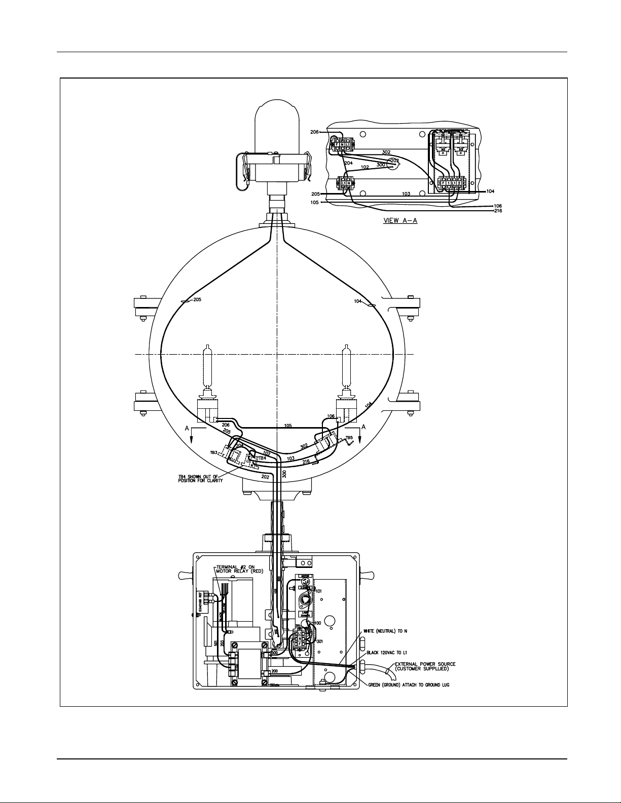
See Figure 2-2. An L-810 obstruction light is available for mounting on top
of the beacon. The obstruction light lights when one or both of the beacon
lamps fail to operate. A fault circuit is also available. The fault circuit can
be wired to a horn or light to serve as an alarm indicating that one or both
of the beacon lamps have failed.
2001 Siemens Airfield Solutions, Incorporated
All rights reserved Issued 5/01
96A0221B Page 2-3
Page 16
RB-6 L-801A (Airport) Rotating Beacon (Export) Description
Figure 2-2. RB-6 Final Assembly with Optional Obstruction Light Wiring
2001 Siemens Airfield Solutions, Incorporated
All rights reserved Issued 5/01
96A0221B Page 2-4
Page 17
RB-6 L-801A (Airport) Rotating Beacon (Export) Description
Optional Heater Assembly
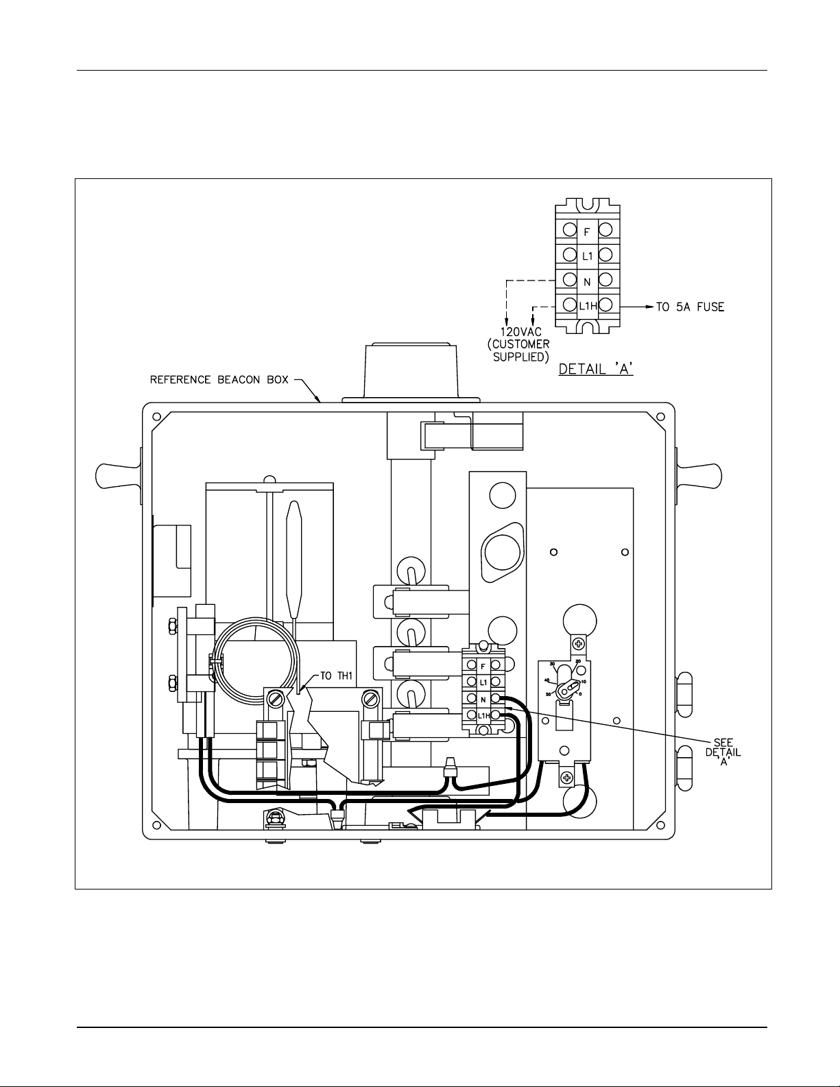
See Figure 2-3. A heater assembly is available for use at temperatures
below -10 °C (+14 °F). The heater turns off at temperatures above +10 °C
(+50 °F).
Figure 2-3. Optional Heater Assembly Wiring
2001 Siemens Airfield Solutions, Incorporated
All rights reserved Issued 5/01
96A0221B Page 2-5
Page 18
RB-6 L-801A (Airport) Rotating Beacon (Export) Description
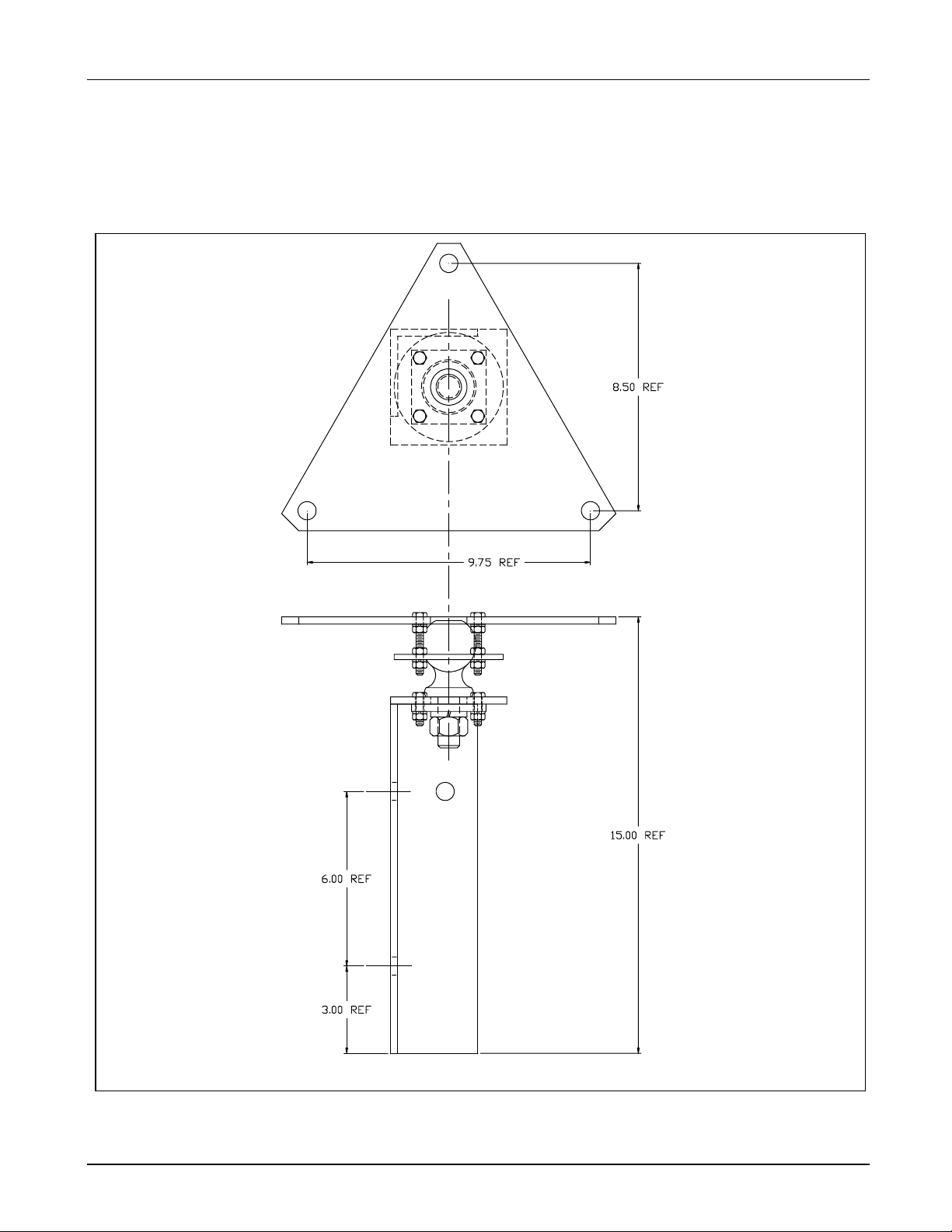
Optional Mounting Bases
Optional bases are available for mounting the beacon on a flat, horizontal
roof or on top of a pole. See Figure 2-4 for optional pole mounting adapter.
An optional roof mounting assembly is shown in Figure 2-5.
Figure 2-4. Optional Pole Mounting Adapter
2001 Siemens Airfield Solutions, Incorporated
All rights reserved Issued 5/01
96A0221B Page 2-6
Page 19

RB-6 L-801A (Airport) Rotating Beacon (Export) Description
Figure 2-5. Optional Roof Mounting Assembly
2001 Siemens Airfield Solutions, Incorporated
All rights reserved Issued 5/01
96A0221B Page 2-7
Page 20

RB-6 L-801A (Airport) Rotating Beacon (Export) Description
Optional Photocell Assembly
4. Theory of Operation
RB-6 Rotating Beacon
Operations
Optional Heater Assembly
Operations
See Figure 7-2 the Wiring Schematics section. An optional photocell
assembly is available to automatically turn the beacon on at dusk and off at
dawn.
This subsection describes the operations of the RB-6, the optional heater
assembly, and the optional photocell assembly.
See Figure 7-1 the Wiring Schematics section. Power is connected to TB1
terminals L1 (120 Vac) and N (neutral). Power is supplied through fuse F1
to motor relay K1. Relay K1 is a motor starting relay. When power is first
applied, 120 Vac is present at K1 pins 2 and 3. Relay pin 3 is connected to
the motor main winding and pin 2 is connected to the start winding. When
the motor is first turned on, it draws a current greater than 4.4 A, energizing
the relay and placing 120 Vac on pin 2. After the motor has reached its
operating speed, the current drops to less than 3.2 A and relay K1 deenergizes. This disconnects 120 Vac from the motor start winding. 120
Vac is continuously connected to the motor main winding at relay K1 pin 3.
Power is supplied to the lamps through fuse F2, brush brackets #2 and #3,
and terminal blocks TB3 and TB4.
See Figure 2-3. The optional heater assembly consists of a 400-watt
heating element, thermostat, and safety fuse. The heater assembly should be
connected through a power cord to a separate circuit breaker, so that it may
remain operable when the beacon is turned off. The circuit breaker should
be switched off during the summer months.
When the temperature drops below +14 °F (-10 °C), the thermostat
activates the heater, which is attached to the motor gear box. The gear box
lubricant is warmed and this facilitates rotation of the beacon when it is
energized; the more effective lubrication which results also extends the
service life of the motor.
2001 Siemens Airfield Solutions, Incorporated
All rights reserved Issued 5/01
96A0221B Page 2-8
Page 21

RB-6 L-801A (Airport) Rotating Beacon (Export) Description
Optional Photocell Assembly
Operations
Optional Obstruction Light
Operations
5. RB-6 Rotating Beacon:
Required Equipment
See Figure 7-2 the Wiring Schematics section. At dusk the decrease in light
on the photocell causes a current to flow through terminal block TBX, the
photocell and into the coil of relay Kl in the photocell relay assembly. This
closes the normally open contact which connects 120 Vac to terminal block
TBX terminal L0. This is connected to terminal block TB1 in the rotating
beacon and starts it operating. At dawn the increase in light on the
photocell stops current from flowing through relay K1 which opens the
contact and shuts down the beacon.
See Figure 7-1 in the Wiring Schematics section. When power is applied to
the RB-6 beacon, lamp #1 illuminates because current is taken through fuse
F2, brush block #2, terminal block TB4 terminal L1, terminal block TB3
terminal L1. Lamp #2 illuminates because current is taken through fuse F2,
brush block #2, terminal block TB4 terminal L1.
Neutral is connected through brush block #3 and terminal blocks TB3 and
TB4 terminal N.
Refer to Table 2-1 for required equipment that is supplied. Refer to
Table 2-2 for required equipment that is not supplied. Refer to the Parts
section for ordering information.
Table 2-1. Required Equipment Supplied
Description Quantity
RB-6 rotating beacon 1
Instruction manual 1
2001 Siemens Airfield Solutions, Incorporated
All rights reserved Issued 5/01
96A0221B Page 2-9
Page 22

RB-6 L-801A (Airport) Rotating Beacon (Export) Description
Table 2-2. Required Equipment Not Supplied
Description Quantity
Wrenches, 7/16 in. 1
Voltmeter 1
Insulation tester 1
Level 1
Lightening rod 1
SO-3 cable, AWG 10 1
Set of screwdrivers As required
Ground wire for lightening rod As required
Set of pliers As required
Liquid glass cleaner As required
Linear barrel scale, 0-16 oz 1
6. Specifications
Input
Beacon Wattage
Lenses
Rated Lamp Life
Lamp Wattage
This subsection describes the specifications for the RB-6, Type L-801A
rotating beacons. Refer to the Parts section for part numbers.
120 Vac, ±10%, 50/60 Hz
Refer to the table below for beacon wattage.
Standard RB-6 Lamp Wattage
(W)
Without optional heater 2100
With optional heater 2500
One pair: one clear, one green
4000 hours
1000 W
2001 Siemens Airfield Solutions, Incorporated
All rights reserved Issued 5/01
96A0221B Page 2-10
Page 23

RB-6 L-801A (Airport) Rotating Beacon (Export) Description
Beam Intensity
Rotation Speed
Heater
Environmental Operating
Conditions
Weight
Refer to the table below.
Beam Direction Measured Beam Intensity
Candelas (cd)
+1 to +2 degrees above horizontal 25,000 (minimum)
+2 to +8 degrees above horizontal 50,000 (minimum)
+8 to +10 degrees above horizontal 25,000 (minimum)
The RB-6 has a rotation speed of 12.5 rpm when operating at 50 Hz.
400 W heating element (optional)
The RB-6 beacon automatically turns on below -10 °C (+14 °F).
The RB-6 beacon automatically turns off above +10 °C (+50 °F).
The RB-6 rotating beacon is designed to operate under the conditions
presented below for temperature, altitude, and relative humidity.
Temperature
-55 to + 55 °C (-67 to +131 °F)
Altitude
Sea level to 10,000 feet (3000 m)
Relative Humidity
Up to 100 %
Wind
Velocities to 100 mph (161 km/h)
Approximately 135 lb (61 kg)
2001 Siemens Airfield Solutions, Incorporated
All rights reserved Issued 5/01
96A0221B Page 2-11
Page 24

RB-6 L-801A (Airport) Rotating Beacon (Export) Description
Dimensions
Clearance for Rotation
Mounting Dimensions
See Figure 2-1. This subsection describes the dimensions for the RB-6
beacon and the obstruction light. Refer to the table below.
RB-6 Beacon RB-6 Beacon
with Obstruction Light
Height: 35-1/4 in. (895.35 mm) 46-1/4 in. (1174.75 mm)
Width: 24 in. (609.6 mm) 24 in. (609.6 mm)
30 in. (762 mm)
See Figure 2-6. Three holes are tapped 1/2−13 UNC.
Figure 2-6. Mounting Holes
2001 Siemens Airfield Solutions, Incorporated
All rights reserved Issued 5/01
96A0221B Page 2-12
Page 25

RB-6 L-801A (Airport) Rotating Beacon (Export) Installation
Section 3
Installation
1. Introduction
2. Unpacking
3. RB-6 Beacon Installation
Mounting
WARNING: Allow only qualified personnel to perform the
following tasks. Observe and follow the safety instructions in
this document and all other related documentation.
This section describes instructions for installing the RB-6 rotating beacon
(Export Version).
Handle equipment very carefully to prevent component damage. Note any
exterior damage to the carton/crate that might lead to detection of
equipment damage. Open the top of the carton/crate. Remove foam
packing from the top of the box. Carefully lift the unit out of the box by the
handles on the side of the motor box.
Unpack the carton/crate upon receipt and check the contents and their
condition. If you note any damage to any equipment, file a claim with the
carrier immediately. The carrier may need to inspect the equipment.
This subsection provides instructions for the installation of the RB-6
rotating beacon (Export Version). Refer to the project plans and
specifications for the specific installation instructions.
The RB-6 rotating beacon comes completely assembled except for
installation of a customer-supplied AWG 10, S0-3 power cord (not
supplied).
Remove the cover plate from the motor box. Inspect the interior to make
sure all parts are tight and have not been loosened in shipment. Reinstall
the cover plate. Mounting adapters furnished are for mounting on a level
surface with the following mounting dimensions: Three holes are tapped
1/2−13 UNC. If the surface is not level, spacers or shims will be needed.
Place a level on top of the motor box and use shims as necessary under the
four corners to bring the beacon to level. Tighten the mounting bolts, four
each #1/4 - 20 length as required.
CAUTION: Do not lift the unit by the head. Failure to observe
this warning may result in equipment damage.
2001 Siemens Airfield Solutions, Incorporated
All rights reserved Issued 5/01
96A0221B Page 3-1
Page 26

RB-6 L-801A (Airport) Rotating Beacon (Export) Installation
Wiring
Optional Heater Wiring
Angle Adjustment
See Figure 7-1 the Wiring Schematics section for final assembly wiring
diagram. An AWG 10, S0-3 power cord (user supplied) must be attached
to the beacon.
To install power cord, perform the following procedure:
1. Remove the motor box cover plate and gasket by removing the four
screws (7/16 wrench required) on the front of the motor box.
2. Route the cable through side hole into box.
3. Connect the power cord at the terminal strip as shown in Figure2-2 in
the Description section.
4. Attach 3-conductor black wire (120 VAC) to terminal marked Ll, white
wire (neutral) to terminal marked N, and green wire (ground) to the
ground lug in the base of the box.
See Figure 2-3 the Description section. The optional heater assembly,
when ordered, is pre-wired at the factory. The power cord for the heater
assembly should be connected from a separate circuit breaker to terminal
block TB1 terminals L1
and N so the heater can be operated when the
H
beacon is off.
All beacons are shipped from the factory preset at an angle of 5 degrees.
To adjust the beacon angle needs, perform the following procedure:
1. See Figure 3-1. Loosen the wing nut (4) holding the head in place.
2. Slide the elevation adjustment device (3) to the desired angle and
tighten nut.
2001 Siemens Airfield Solutions, Incorporated
All rights reserved Issued 5/01
96A0221B Page 3-2
Page 27

RB-6 L-801A (Airport) Rotating Beacon (Export) Installation
1
2
3
4
4
Front View
Figure 3-1. Adjusting Beacon Angle
1. Lens Clip
2. Lamp
3. Elevation Adjustment Device
4. Wing Nut
Side View
2001 Siemens Airfield Solutions, Incorporated
All rights reserved Issued 5/01
96A0221B Page 3-3
Page 28

RB-6 L-801A (Airport) Rotating Beacon (Export) Installation
Export Beacon Installation Requirement
Requirement for export beacon installation only: A fence with a padlock
gate shall be installed around the beacon to prevent unauthorized entry.
2001 Siemens Airfield Solutions, Incorporated
All rights reserved Issued 5/01
96A0221B Page 3-4
Page 29

RB-6 L-801A (Airport) Rotating Beacon (Export) Maintenance
Section 4
Maintenance
1. Introduction
2. Maintenance Schedule
Interval Maintenance Task Action
Daily Check for lamp failure. Replace lamp. Refer to Replacing Lamps in this
Check for 24-30 flashes per minute to see
if beacon has correct rpm.
Bimonthly (60 days) Check for dirty or pitted slip rings and
brushes.
Check for loose lens retainer. Tighten screws or clamps on the lens retainer.
Check for dirty or pitted photocell relay
contacts.
Check for dirty lamp glassware. Clean lamp glassware.
Semi-annually Check for input voltage out of tolerance. Record reading. If the voltage is out of tolerance,
Verify beam elevation. Adjust beam elevation. Check the angle indicator
Poor contact on the electrical switches and
contacts.
Check for loose lightening rod
connections.
This section provides maintenance information for the RB-6 rotating
beacon (Export Version).
To keep RB-6 rotating beacons operating efficiently, follow a preventive
maintenance schedule. Refer to Table 4-1. Refer to FAA AC 150/5340-26
for more detailed information.
Table 4-1. RB-6 Rotating Beacon (Export Version) Maintenance
section.
Check the motor and shaft bearing.
Clean slip rings and brushes. Replace worn
brushes, deeply pitted slip rings, or shaft. Refer to
Replacing Brushes and Brush Brackets and
Cleaning Slip Rings and Brushes in this section.
Clean photocell relay contacts. Replace if badly
pitted.
contact the power company or install an
autotransformer. The voltage is out of tolerance if it
is not within ±10% rated lamp voltage.
on the beacon head assembly.
If the contacts are corroded, repair or replace.
Tighten loose connections. Check and record
ground resistance.
Continued on next page
2001 Siemens Airfield Solutions, Incorporated
All rights reserved Issued 5/01
96A0221B Page 4-1
Page 30

RB-6 L-801A (Airport) Rotating Beacon (Export) Maintenance
Table 4-1. RB-6 Rotating Beacon (Export Version) Maintenance
Interval Maintenance Task Action
Annually Check to see if the beacon is level. Make the beacon level, if necessary. Check the
level in four directions.
Check for loose or broken wiring, lugs,
and conduit.
Check for cracked or deteriorated gaskets
or deteriorated weatherproofing.
3. Maintenance Procedures
This subsection describes the following maintenance procedures:
• replacing lamp
• adjusting lamp beam
• replacing brushes
• cleaning lenses
• cleaning head
• cleaning vents
• cleaning slip rings and brushes
• lubricating parts
Replacing Lamp
To replace the lamp, perform the following procedure:
1. See Figure 3-1 in the Installation section. Loosen the two lens clips (1)
on the front of the beacon.
2. Grasp the top of the lamp (2), push downward, and turn
counterclockwise approximately 120 degrees. Lift the lamp out of the
socket.
3. Carefully insert the replacement lamp into the socket.
NOTE: Make sure the lamp filament is vertical before closing the lens
cover and tightening the hexagonal screw.
WARNING: The lens temperature can be as high as 373 °F
(189 °C). Allow one-half hour for the lamps to cool before
opening the lens cover. Failure to observe this warning may
result in personal injury or equipment damage.
Repair or renew wiring when needed. Tighten
loose lugs, conduit supports, and connections.
Replace broken brackets.
Replace gaskets or weatherproofing, if necessary.
2001 Siemens Airfield Solutions, Incorporated
All rights reserved Issued 5/01
96A0221B Page 4-2
Page 31

RB-6 L-801A (Airport) Rotating Beacon (Export) Maintenance
Replacing Brushes and Brush
Brackets
Replace all three brushes at the same time to provide even wear.
To replace the brushes and brush brackets, perform the following
procedure:
1. See Figure 4-1. Remove the two screws, lockwashers, and hex nuts
holding the brush block assembly (1) to the motor box.
1
6
7
1
8
5
4
3
2
Side Vie w
Side View of Bracket
Figure 4-1. Brush Block Assembly
1. Brush Block Assembly 4. Brush Block Screw 7. Brush
2. Brass Hex Nut 5. Wire 8. Brush Bracket
3. Hex Nut and Lockwasher 6. Brush Screw 9. Drive Pint
Front View
2
9
2001 Siemens Airfield Solutions, Incorporated
All rights reserved Issued 5/01
96A0221B Page 4-3
Page 32

RB-6 L-801A (Airport) Rotating Beacon (Export) Maintenance
2. Lift the brush block assembly away from the shaft. Be careful not to
place any strain on the wires.
3. Remove the screw (6) holding the brush (7) to the brush bracket (8).
4. Install new brushes on the brush block by performing the following
procedure:
a) Use a screwdriver blade to loosen and remove the 2 x 1/4 round
head drive pin (9) on the old bracket.
b) Remove the outer hex nut and lockwasher (3), and wire (5) from
the screw holding the end of the bracket to the brush block.
c) Remove solder from the remaining brass hex nut (2). Remove the
hex nut and brush bracket from the screw on the brush block.
CAUTION: Do not remove the screw (4). Failure to observe
this warning may result in equipment damage.
d) See Figure 4-2. Pre-bend (4) the new brush bracket(s) (2) so that
the bend in the new bracket is similar to the bend in the old
bracket.
2001 Siemens Airfield Solutions, Incorporated
All rights reserved Issued 5/01
96A0221B Page 4-4
Page 33

RB-6 L-801A (Airport) Rotating Beacon (Export) Maintenance
1
3
2
4
4
6
5
7
Figure 4-2. Pre-Bending New Brush Brackets
1. Brush 4. Pre-Bend Brush Bracket Here 7. Bend Brush Bracket Here to Release Tension
2. Brush Bracket 5. Attach Spring Scale Here
3. Slip Ring Assembly 6. Direction of Required Tension
2001 Siemens Airfield Solutions, Incorporated
All rights reserved Issued 5/01
96A0221B Page 4-5
Page 34

RB-6 L-801A (Airport) Rotating Beacon (Export) Maintenance
e) Install the brush bracket assembly.
f) Use a customer-supplied spring scale attached to the head of the
screws (5) to check the tension of the brush (1) against the shaft
assembly (3). The brushes must have a tension of 14 + 2 oz
against the shaft. The spring scale is a Linear Barrel Scale (0-16
oz in 1/4 oz increments).
g) If too much tension exists, release tension by bending the brush
bracket (7).
h) Place a new bracket on the screw, install the drive pin on the
bracket, and use a 60/40 solder to secure the brass hex nut to the
screw and bracket. Then reinstall the wire, lockwasher, and outer
hex nut on the screw.
Cleaning Lenses
Cleaning Head Assembly
Cleaning Slip Rings and
Brushes
Lubricating Parts
Clean lenses periodically with alcohol or glass cleaner and soft cloth.
Wipe dry with a clean soft cloth.
Remove dust and dirt from the head assembly using a soft cloth or sponge
with soap and water.
To clean slip rings and brushes, follow the guidelines below.
• Clean the slip rings and brushes with a cloth moistened with an
appropriate solvent that will not leave a film or residue.
• If sparking or pitting occurs, smooth rings with 420 sandpaper. Avoid
sanding, if possible. Sanding produces a raw copper surface that
shortens brush life.
• Replace brushes showing excessive wear.
NOTE: It is recommended that all three brushes be replaced at the same
time to provide even wear.
WARNING: If the brushes are worn down to the brush
bracket, the bracket may damage the slip rings. Replace the
brushes worn to 1/8 inch (3.175 mm) of the bracket edge.
All moving parts are permanently lubricated and will not require further
attention.
2001 Siemens Airfield Solutions, Incorporated
All rights reserved Issued 5/01
96A0221B Page 4-6
Page 35

RB-6 L-801A (Airport) Rotating Beacon (Export) Troubleshooting
Section 5
Troubleshooting
1. Introduction
2. Troubleshooting
Procedures
Problem Possible Cause Corrective Action
1. Short lamp life
Loose connections Tighten connections.
Excess vibrations Replace bearing or shaft.
Low brush pressure Adjust brush bracket or replace brush
Bad socket Replace socket.
Voltage or voltage spikes greater than
126 Vac
This section contains troubleshooting information. This information covers
only the most common problems that you may encounter. If you cannot
solve the problem with the information given here, contact your local
Siemens Airfield Solutions representative for help.
Refer to the table below for troubleshooting procedures.
WARNING: Allow only qualified personnel to perform the
following tasks. Observe and follow the safety instructions in
this document and all other related documentation.
WARNING: De-energize the circuit and lock out the circuit or
regulator so that the circuit cannot be energized by remote
means before attempting to service the fixture.
assembly. Refer to Replacing Brushes and
Brush Brackets in the Maintenance section.
Check input voltage. Record reading. If the
voltage is out of tolerance, contact the power
company or install an autotransformer. The
voltage is in tolerance if it is within ±10%
rated lamp voltage.
Continued on next page
2001 Siemens Airfield Solutions, Incorporated
All rights reserved Issued 5/01
96A0221B Page 5-1
Page 36

RB-6 L-801A (Airport) Rotating Beacon (Export) Troubleshooting
Problem Possible Cause Corrective Action
2. Lamp not lighting
3. Photocell not
operating
4. Poor beacon visibility
5. Motor not turning
6. Motor not turning
during cold weather
7. Heater not operating
Lamp defective Replace lamp. Refer to Replacing Lamp in
the Maintenance section.
Blown fuse Replace fuse F2 (30 A, Slo-Blo).
Photocell inoperable See Photocell not operating in this table.
Brush assembly not working Replace brush assembly. Refer to Replacing
Brushes and Brush Brackets in the
Maintenance section.
Loose or broken wire Replace cordset or socket.
Photocell defective Replace photocell.
Relay defective Replace relay.
Loose or broken wire Repair or replace wire.
Lamp filament not at focal point of
reflector
Move socket up or down so the lamp filament
is at the focal point of the reflector.
Dirty lenses Clean lenses after they cool off.
Blown fuse Replace fuse F1 (3.2 A, Slo-Blo).
Motor relay defective Replace relay.
Motor defective Replace motor.
Shaft bearing seized Replace defective bearing.
Loose or broken wire Repair or replace wire.
Heater inoperable Refer to Heater not operating in this table.
Blown fuse Replace fuse F3 (5 A, Slo-Blo).
Thermostat defective Replace thermostat.
Heater defective Replace heater.
Loose or broken wire Repair or replace wire.
2001 Siemens Airfield Solutions, Incorporated
All rights reserved Issued 5/01
96A0221B Page 5-2
Page 37

RB-6 L-801A (Airport) Rotating Beacon (Export) Parts
Section 6
Parts
1. Introduction
2. Using the Illustrated Parts
List
Item Description Part Number Note
NS Assembly
T1 Assembly
Part xxxxxxxx
Part
To order parts, call Siemens Airfield Solutions Customer Service or your
local representative. Use this four-column parts list, and the accompanying
illustration, to describe and locate parts correctly.
The Item column numbers correspond to the numbers that identify parts in
illustrations following each parts list. NS (not shown) indicates that a listed
part is not illustrated.
The Description column gives the part name, as well as its dimensions and
other characteristics when appropriate. Parts are indented under an
assembly to show the part that applies to your particular sign module.
The Part Number column gives the Siemens Airfield Solutions part number.
xxxxxxxx A
xxxxxxxx
The Note column contains letters that refer to notes at the end of each parts
list. Notes contain special ordering information.
2001 Siemens Airfield Solutions, Incorporated
All rights reserved Issued 5/01
96A0221B Page 6-1
Page 38

RB-6 L-801A (Airport) Rotating Beacon (Export) Parts
3. RB-6 Rotating Beacon
Final Assembly Parts List
Item Description Part Number Note
A2 Head assembly
A1 Box assembly (Export)
A3 Optional heater assembly
S1 Silicone rubber sealant 67A0006-3
See Figure 6-1.
The RB-6 Beacon Export Version final assembly part number is
44D0221-X.
44D0751
44D4740-3
44B0789
2001 Siemens Airfield Solutions, Incorporated
All rights reserved Issued 5/01
96A0221B Page 6-2
Page 39

RB-6 L-801A (Airport) Rotating Beacon (Export) Parts
S1
A2
A3
Figure 6-1. RB-6 Rotating Beacon Final Assembly (Export Version)
A1
2001 Siemens Airfield Solutions, Incorporated
All rights reserved Issued 5/01
96A0221B Page 6-3
Page 40

RB-6 L-801A (Airport) Rotating Beacon (Export) Parts
4. Head Assembly
(Single Head) Parts List
Item Description Part Number Note
M6 Lens ring
M9
M11
M10
H5
H6
M8
TB1
M1
H3
H2
NS
NS Adhesive 67A0005
NS: Not Shown
Gasket, lens, RB-6, 14−1-1/16 in. (357.1875 mm) O.D.
Gasket, lens, RB-6, 15−7/8 in. (403.225 mm) O.D.
Gasket, conical ring, RB-6, 21−1/4 in. (539.75 mm) O.D.
Lens, green, 14 in. (355.6 mm) 63A0168
Lens, clear, 14 in. (355.6 mm) 63A0169
Reflector assembly 62D0455
Terminal block, 22−10 AWG, 300 V, 50 A
Lens clip 61A0074
Strike 61A0051-3
Catch 61A0051-1
Silicone sealant 67A0009
See Figure 6-2.
Head assembly (single head) part number is 44C0238-X.
62D0303
63A0167
63A0172
63A0170
72A0016
2001 Siemens Airfield Solutions, Incorporated
All rights reserved Issued 5/01
96A0221B Page 6-4
Page 41

RB-6 L-801A (Airport) Rotating Beacon (Export) Parts
M1
Figure 6-2. Head Assembly (Single Head)
H5
M6
M10
M11
M8
H3
M9
H6
H2
2001 Siemens Airfield Solutions, Incorporated
All rights reserved Issued 5/01
96A0221B Page 6-5
Page 42

RB-6 L-801A (Airport) Rotating Beacon (Export) Parts
M
5. Box Assembly Parts List
Item Description Part Number Note
H24 Bearing
A3 Shaft assembly
H20 Fiber gear, 48 teeth
A2
A5 Lid assembly 44B0285
otor assembly, export, 115 V, 50/60 Hz, 26-teeth gear
See Figure 6-3.
The box assembly part number is 44C0750-X.
75A0004
44C0393
68A0002
44B0998-2
2001 Siemens Airfield Solutions, Incorporated 96A0221B Page 6-6
All rights reserved Issued 5/01
Page 43

RB-6 L-801A (Airport) Rotating Beacon (Export) Parts
A3
A2
A5
Figure 6-3. Box Assembly
H20
H24
2001 Siemens Airfield Solutions, Incorporated 96A0221B Page 6-7
All rights reserved Issued 5/01
Page 44

RB-6 L-801A (Airport) Rotating Beacon (Export) Parts
6. Motor Assembly Parts List
Item Description Part Number Note
MT1 Gear motor, 50/60 Hz, 115 V, 26-28 rpm, Von Weise Gear Co.,
#V0378AA88, Series K83
M1 Motor mount, Export
H3 Gear, 26 teeth, Export 68A0007
See Figure 6-4.
Motor assembly part number is 44B0998-X.
69C0006
62C0179-2
Figure 6-4. Motor Assembly
H3
M1
MT1
2001 Siemens Airfield Solutions, Incorporated 96A0221B Page 6-8
All rights reserved Issued 5/01
Page 45

RB-6 L-801A (Airport) Rotating Beacon (Export) Parts
7. Brush Block Assembly
Parts List
Item Description Part Number Note
H10 Brush
F3 Fuse, 3.2 A, Slo-Blo
F2 Fuse, 30 A, Slo-Blo 47A0024
See Figure 6-5.
Brush block assembly part number is 44A0222.
76A0001
47A0003
2001 Siemens Airfield Solutions, Incorporated 96A0221B Page 6-9
All rights reserved Issued 5/01
Page 46

RB-6 L-801A (Airport) Rotating Beacon (Export) Parts
F3
F2
Side View Front View
H10
Side View of Bracket
Figure 6-5. Brush Block Assembly
2001 Siemens Airfield Solutions, Incorporated 96A0221B Page 6-10
All rights reserved Issued 5/01
Page 47

RB-6 L-801A (Airport) Rotating Beacon (Export) Parts
8. Photocell Contactor
Assembly Parts List
Item Description Part Number Note
1 Photocell
2 Socket
3 Terminal block
4 Relay
See Figure 6-6.
Photocell contactor assembly part number is 44B0812.
48A0089
49A0095
72A0016
53A0126-1
2001 Siemens Airfield Solutions, Incorporated 96A0221B Page 6-11
All rights reserved Issued 5/01
Page 48

RB-6 L-801A (Airport) Rotating Beacon (Export) Parts
1
2
3
4
Figure 6-6. Photocell Contactor Assembly
2001 Siemens Airfield Solutions, Incorporated 96A0221B Page 6-12
All rights reserved Issued 5/01
Page 49

RB-6 L-801A (Airport) Rotating Beacon (Export) Parts
9. Heater Assembly Parts
List
Item Description Part Number Note
HT1 Heater element, 400 W
F1 Fuse, 5 A, Slo-Blo
F1 Fuse holder
TH1 Thermostat, Dayton #2E998
TB1 Terminal block 72A0016
See Figure 6-7.
Heater assembly part number is 44B0789.
85A0050
47A0107
47A0061
54A0010
2001 Siemens Airfield Solutions, Incorporated 96A0221B Page 6-13
All rights reserved Issued 5/01
Page 50

RB-6 L-801A (Airport) Rotating Beacon (Export) Parts
HT1
Figure 6-7. Heater Assembly
TB1
F1
TH1
2001 Siemens Airfield Solutions, Incorporated 96A0221B Page 6-14
All rights reserved Issued 5/01
Page 51

RB-6 L-801A (Airport) Rotating Beacon (Export) Parts
10. Reflector Assembly Parts
List
Item Description Part Number Note
1 Reflector
2 Lamp support
3 Socket, phenolic
4 Lamp, 1000 w 48A0032
See Figure 6-8.
The reflector assembly part number is 44D0981.
62D0455
62B0323
49A0002
2001 Siemens Airfield Solutions, Incorporated 96A0221B Page 6-15
All rights reserved Issued 5/01
Page 52

RB-6 L-801A (Airport) Rotating Beacon (Export) Parts
1
2
1
3
4
2
Front View
Figure 6-8. Reflector Assembly
3
Side View
2001 Siemens Airfield Solutions, Incorporated 96A0221B Page 6-16
All rights reserved Issued 5/01
Page 53

RB-6 L-801A (Airport) Rotating Beacon (Export) Parts
11. Obstruction Light and
Relay Parts List
Item Description Part Number Note
1 Obstruction light assembly
2 Silicone rubber sealant
3 Relay assembly 44B0435
See Figure 6-9.
The optional obstruction light part number is 44B0805.
44B0804
67A0006-1
2001 Siemens Airfield Solutions, Incorporated 96A0221B Page 6-17
All rights reserved Issued 5/01
Page 54

RB-6 L-801A (Airport) Rotating Beacon (Export) Parts
1
2
3
Figure 6-9. Obstruction Light
2001 Siemens Airfield Solutions, Incorporated 96A0221B Page 6-18
All rights reserved Issued 5/01
Page 55

RB-6 L-801A (Airport) Rotating Beacon (Export) Parts
12. Optional Assemblies
Parts List
Item Description Part Number Note
NS Photocell contractor assembly
NS Roof mounting assembly
NS Pole mounting assembly
NS Heater assembly
NS Obstruction light assembly 44D0805
Refer to the table below for optional assemblies part numbers.
44B0812
44D0351-1
44C0259
44B0789
2001 Siemens Airfield Solutions, Incorporated 96A0221B Page 6-19
All rights reserved Issued 5/01
Page 56

RB-6 L-801A (Airport) Rotating Beacon (Export) Wiring Schematics
Section 7
Wiring Schematics
1. Introduction
Wiring Schematics
RB-6 Beacon with Optional
Heater Wiring
This section provides wiring schematics for the RB-6 beacon (Export
Version).
Wiring schematics and diagrams for Export Version RB-6 beacons include
the following:
• RB-6 beacon with optional heater wiring schematic
• photocell assembly wiring schematic
See Figure 7-1.
2001 Siemens Airfield Solutions, Incorporated 96A0221B Page 7-1
All rights reserved Issued 5/01
Page 57

RB-6 L-801A (Airport) Rotating Beacon (Export) Wiring Schematics
Figure 7-1. RB-6 Beacon with Optional Heater Wiring Schematic
2001 Siemens Airfield Solutions, Incorporated 96A0221B Page 7-2
All rights reserved Issued 5/01
Page 58

RB-6 L-801A (Airport) Rotating Beacon (Export) Wiring Schematics
Optional Photocell Assembly
Wiring
See Figure 7-2.
Figure 7-2. Optional Photocell Assembly Wiring Schematic
2001 Siemens Airfield Solutions, Incorporated 96A0221B Page 7-3
All rights reserved Issued 5/01
 Loading...