

Page 1
Siemens Building Technologies CE1N2226E / 01.02.2000
Landis & Staefa Division 1/8
2
226
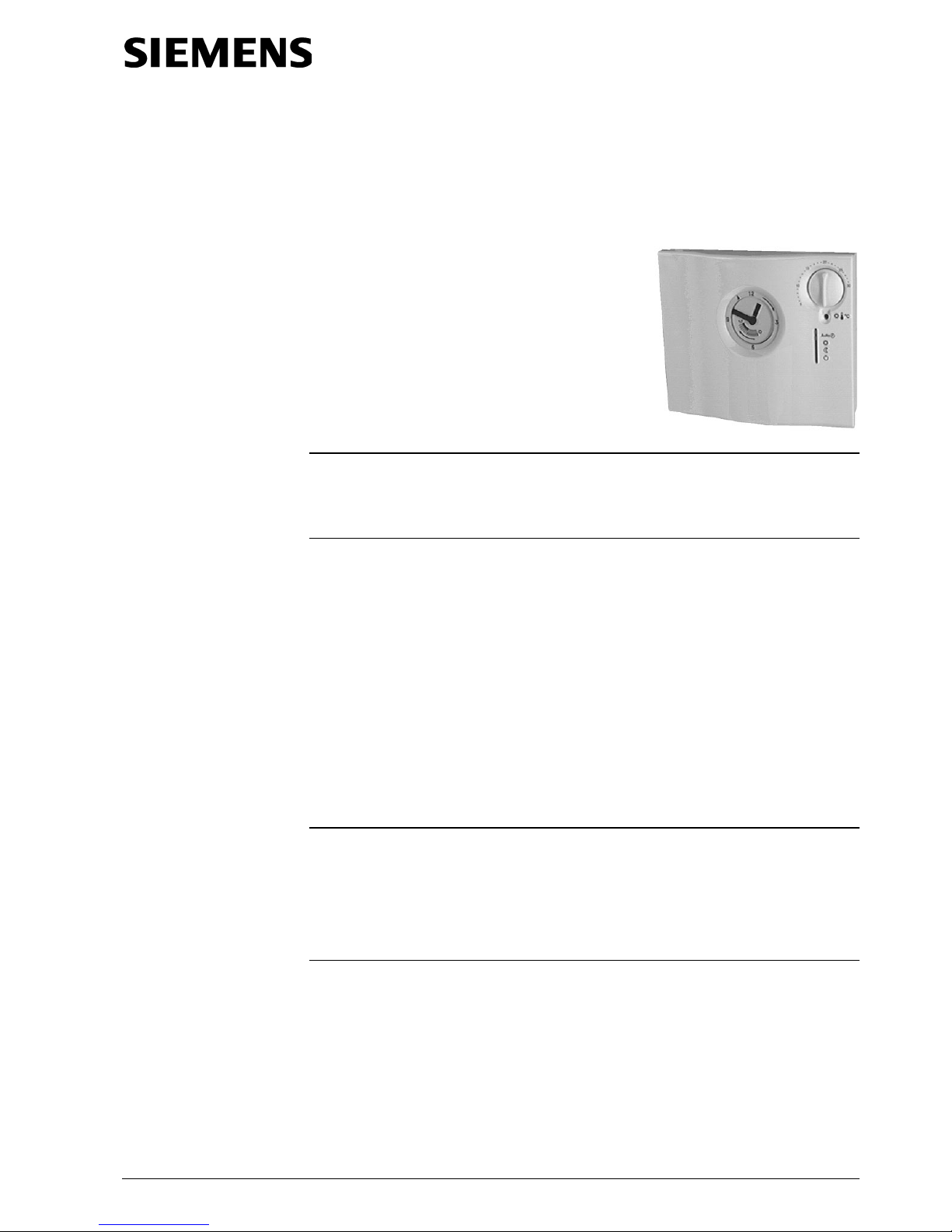
Self-learning Room
Temperature Controller RAV12…
with analogue 24-hour or weekly time switch
and possibility of remote control
Mains powered room temperature controller featuring straightforward operation.
Self-learning two-position controller providing PID control (patented).
Freely selectable switching times.
Room temperature control in:
–
Single-family and holiday houses
–
Apartments and office spaces
–
Individual rooms and consulting rooms
–
Commercially used spaces
For the control of the following pieces of equipment:
–
Solenoid valves of instantaneous water heaters
–
Solenoid valves of atmospheric gas burners
–
Forced draught gas and oil burners
–
Circulating pumps in heating systems
–
Electric direct heating
–
Fans of electric storage heaters
–
Zone valves (normally closed)
• PID control
• Self-learning or selectable switching cycle
• Freely adjustable 24-hour mode
• Freely adjustable weekly mode with weekly time switch
• Frost protection function
• Minimum limitation of set point
Room temperature controller, AC 230 V mains powered
without time switch (not soled in this form)
RAV12
Room temperature controller, AC 230 V mains powered
with analogue 24-hour time switch
RAV12.1
Room temperature controller, AC 230 V mains powered
with analogue weekly time switch
RAV12.7
Analogue 24-hour time switch
AUZ3.1
Analogue weekly time switch
AUZ3.7
When ordering, please give type reference according to "Type summary".
The unit is supplied with all necessary features.
Use
Functions
Type summary
Ordering
Delivery
Page 2
CE1N2226E / 01.02.2000 Siemens Building Technologies
2/8 Landis & Staefa Division
Plastic casing with analogue 24-hour or weekly time switch, easily accessible operating
elements and removable cover. The base plate can be fitted to all commercially available recessed conduit boxes or directly on the wall and can then be wired before attaching the controller to it. The casing accommodates the electronics with the DIP
switch. The potential-free changeover contact and the connection terminals are located
on the base plate.
2226Z02
6
5
4
3
2
1
13
12
11
10
9
8
7
4
2
1
24
23
22
21
20
17
14
15
16
18
19
6
5
3
10
15
20
25
30
5
5
10
15
20
25
30
°C
°C
AUTO
Analogue time switch
Tappets tilted
outward
for
normal
temperature
Tappets tilted
inward
for
economy
temperature
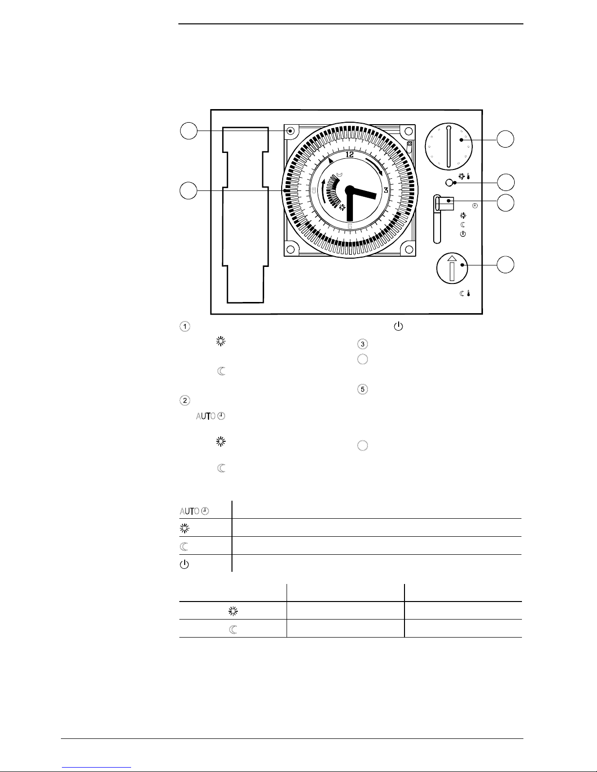
Operating mode selector
Heating periods according to
tappet settings on time switch
Continuous normal temperature
Continuous economy temperature
Standby with frost protection
Setting knob for normal temperature
Setting knob for economy tempera-
ture
LED
Signalisation of override by remote
control or activation of relays by
switched on heating system.
Position for time switch
Heating periods according to tappet settings on time switch
Continuous normal temperature
Continuous economy temperature
Standby with frost protection
Factory settings Setting range
20 °C 5…30 °C
15 °C 5…30 °C
When the LED lights up, the following is signalised:
•
With a connected remote control the unit is overridden from the outside (e.g. by a
telephone switch).
•
When no remote control is connected, the relays is activated and the heating is
switched on.
Mechanical design
Display and operating
elements
Operating modes
Set points
LED
Page 3
Siemens Building Technologies CE1N2226E / 01.02.2000
Landis & Staefa Division 3/8
2224Z17
DIP-Switch
Reset
Temp.
Offset
If the measured room temperature does not agree with the temperature set on the knob,
the temperature detector can be recalibrated.
This can be done by adjusting a potentiometer that is located on the rear of the unit.
First, the unit must be removed from the socket.
The possible settings on the potentiometer are:
10
15
20
25
30
5
(°C) (°C) Pos.
22.00 20.00 8
21.75 20.00 7
21.50 20.00 6
21.25 20.00 5
21.00 20.00 4
20.75 20.00 3
20.50 20.00 2
20.25 20.00 1
20.00 20.00 0 <= Factory setting
19.75 20.00 F
19.50 20.00 E
19.25 20.00 D
19.00 20.00 C
18.75 20.00 B
18.50 20.00 A
18.25 20.00 9
After the corrections are made, the new setting must be confirmed by pressing the reset
button.
Otherwise the previous settings are still active!
After the reset the controller
can be remounted to the socket.
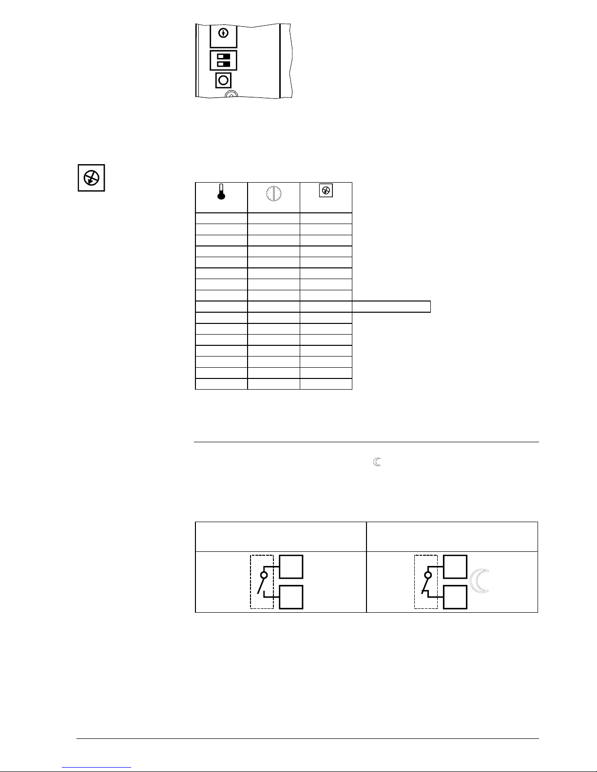
With the help of a suitable remote operation unit, the
controller
can be switched to the
economy temperature set for operating mode . Changeover takes place through the
making of a
potential-free contact
connected to terminals T1 and T2.
The LED indicates this by being light.
After the contact opens, the selected operating mode becomes active again.
Operation according to the settings made
on the controller
Continuous economy temperature
T2
T1
2226Z04
T2
T1
2226Z05
Suitable remote operation units are e.g.:
– Telephone modem
– manual switch
– window switch
– presence detector
– central unit
Calibration of detector
2224Z04
Remote operation
Page 4

CE1N2226E / 01.02.2000 Siemens Building Technologies
4/8 Landis & Staefa Division
123
PID 12
PID 6
2-Pt
2224Z01
Self learning
4
The RAV12… is a two-position controller providing PID control. The room temperature
is controlled through the cyclic switching of a regulating unit..
The controller is supplied with an active self-learning mode, which enables it to automatically adapt to the controlled system (type of building construction, type of radiators,
size of rooms, etc.). After a certain learning period, the controller optimises its parameters and then operates in the mode it has learned.
In exceptional cases, where the self-learning mode may not be adequate, it is possible
to choose between PID 12, PID 6 or 2-Pt mode:
Switching cycle of 12 min for normal or slow controlled systems (e.g. massive building
structures, large spaces, cast-iron radiators, oil burners).
Switching cycle of 6 min for fast controlled systems (e.g. light building structures, small
spaces, plate radiators or convectors, gas burners).
Pure two-position control with a switching differential of 0.5 °C (±0.25 °C) for very difficult controlled systems with considerable outside temperature variations.
Standard 5…30 °C 5…30 °C
Version 1 * 20 °C 15 °C
Version 2 * 18…22 °C 13…17 °C
Version 3 * 15…25 °C 10…20 °C
* upon request
The unit has an opening for fitting a plug-in type switch.
If desired, the time switch fitted can be replaced by another. The electrical connections
to the controller are established via a terminal strip so that no wiring is required.
The
time switches can only be mounted in one position.
The analogue time switches are equipped with a quartz clock The switching dial is
equipped with tappets that can be tilted. The heating periods are entered by tilting the
tappets within the required period of time:
•
Tappets tilted outward: Normal temperature
•
Tappets tilted inward: Economy temperature
24-hour time switch Weekly time switch
The 24-hour time switch has a 24-hour
switching dial. It carries 96 tappets, which
means four tappets per hour, giving a
resolution of 15 minutes. The shortest
possible heating period also is 15 minutes.
The weekly time switch has a 7-day
switching dial. It carries 84 pairs of tappets, which means 12 pairs of tappets or
24 individual tappets per day. The resolution is thus one hour. However, since - for
mechanical reasons - at least two tappets
need to be tilted together to set one heating period, the shortest possible heating
period is two hours.
Technical features
DIP-Switch
Control
Self-learning mode
PID 12 mode
PID 6 mode
2-Pt mode
Setting knobs
Analogue time switches
Page 5

Siemens Building Technologies CE1N2226E / 01.02.2000
Landis & Staefa Division 5/8
•
The room temperature controller should be fitted in the main living room.
•
The place of installation should be chosen so that the sensor can capture the room
temperature as accurately as possible, without being affected by direct solar radiation or other heating or cooling sources.
•
Mounting height is approx. 1.5 m above the floor.
•
The unit can be fitted to most commercially available recessed conduit boxes or di-
rectly on the wall.
•
When installing the room temperature controller, the base plate must first be fitted
and wired. Then, the unit is engaged at the top, swung downward and secured with a
screw.
•
For more detailed information, please refer to the installation instructions supplied
with the controller.
•
For the electrical installation, the local safety regulations and standards must be
complied with.
•
The control characteristics can be changed with the help of the DIP switches located
at the rear of the unit.
•
If the reference room is equipped with thermostatic radiator valves, they must be set
to their fully open position.
•
If the measured room temperature does not agree with the set room temperature on
the setting knob, the detector should be recalibrated (please refer to "Calibration of
detector").
Operating voltage AC 230 V
- conformity to
EEC directive 89/336/EEC
low voltage directive 73/23/EEC
Switching capacity of relays
Voltage AC 24…250 V
Current 8 (3.5) A
Measuring element NTC 68 kΩ at 25 °C
Measuring range 0…40 °C
Time constant 2 min max.
Set point setting range
Normal temperature 3…29 °C
Economy temperature 3…29 °C
Resolution of analogue time switches
24-hour time switch 15 min
Weekly time switch 60 min
Set point for frost protection 5 °C
Insulation class
to EN 60730-1 II
Degree of protection
to EN 60529 IP 30
Electromagnetic compatibility
Immunity EN 50082-2
Emissions EN 50081-1
Perm. ambient temperature
Operation 3…35 °C
Storage -25…+60 °C
Perm. ambient humidity
to DIN 40040 G
Weight 0.2 kg
Colour White
RAL 9003
Notes
Engineering
Fitting and installation
Commissioning
Technical Data
Page 6

CE1N2226E / 01.02.2000 Siemens Building Technologies
6/8 Landis & Staefa Division
Lx
L1
Y1
M1
N1
AC 230 V
L2
N
L
AC 24...250 V
2226A01
S1
T1 T2
LLx
NNx
L Live, AC 230 V Nx Neutral AC 24...250 V
Lx Live, AC 24...250 V N1 RAV12.. controller
L1 N.O. contact, AC 24…250 V /
8 (3.5) A
S1T1Remote operating unit (potential-free)
Signal "remote operation"
L2 N.C. contact AC 24...250 V T2 Signal "remote operation"
M1 Circulating pump Y1 Regulating unit
N Neutral AC 230 V
T
T
F1
F2
N1
M1
Y2
2222S01
T
T
F1
F2
N1
M1
Y2
2222S02
T T
Instantaneous water heater) Atmospheric gas burner
T
N1
Y1
2222S03
M1
Circulating pump with pre-control by manual mixing valve
F1 Thermal reset limit thermostat N1 RAV12.. room temperature controller
F2 Manual reset safety limit thermostat Y1 Manually operated three-port valve
M1 Circulating pump Y2 Solenoid valve
Connection diagram
Application
examples
Page 7

Siemens Building Technologies CE1N2226E / 01.02.2000
Landis & Staefa Division 7/8
138
104
37
2226M01
2226M02
Dimensions
Page 8

CE1N2226E / 01.02.2000 Siemens Building Technologies
8/8 Landis & Staefa Division
© 1999 Siemens Building Technologies Ltd. Subject to change
 Loading...