

Page 1

RAS
RAS network
Setting instructions
RX
© Siemens AG 1994
The reproduction, transmission or
use of th is do cu ment or its con ten ts
is not permitted without express
written authority. Offenders will be
liable for damages. All rights,
including rights created by patent
grant or registration of a utility
model _or_ design,_are_ reserved.
Register 04
RX99-051.032.02.01.02 English 03.95
Replaces : RX99-051.032.01.01.02, R99-051.032.12.03
Page 2

0 - 2Revision
Chapter Page Rev.
0 0-1 to 0-4 01
1 1-1 to 1-2 01
2 2-1 to 2-2 01
3 3-1 to 3-8 01
4 4-1 to 4-2 01
5 5-1 to 5-6 01
6 6-1 to 6-4 01
7 7-1 to 7-2 01
8 8-1 to 8-2 01
Chapter Page Rev.
RAS Register 04 RX99-051.032.02 TDRX1 Siemens AG
Rev. 01 03.95 Medical Engineering
Page 3

Contents 0 - 3
Page
1 _______General_______________________________________________________1 - 1
Tools and measurement devices required. . . . . . . . . . . . . . . . . . . . . . . . 1 - 1
Documentation required . . . . . . . . . . . . . . . . . . . . . . . . . . . . . . . 1 - 1
Safety instructions . . . . . . . . . . . . . . . . . . . . . . . . . . . . . . . . . . 1 - 1
Abbreviations used . . . . . . . . . . . . . . . . . . . . . . . . . . . . . . . . . 1 - 1
Inserting the RAS ring. . . . . . . . . . . . . . . . . . . . . . . . . . . . . . . . . . 1 - 2
Methodology. . . . . . . . . . . . . . . . . . . . . . . . . . . . . . . . . . . . . 1 - 2
2 _______RAS programming for DFR systems_______________________________2 - 1
POLYSPOT/POLYTRON S PLUS. . . . . . . . . . . . . . . . . . . . . . . . . . . . 2 - 1
FLUOROSPOT H . . . . . . . . . . . . . . . . . . . . . . . . . . . . . . . . . . . . 2 - 1
3 _______Starting up RAI I.I./TV adapter N93 ________________________________3 - 1
4 _______RAS-programming for the generator_______________________________4 - 1
POLYDOROS 50S/80S . . . . . . . . . . . . . . . . . . . . . . . . . . . . . . . . . 4 - 1
POLYDOROS SX 50/80 . . . . . . . . . . . . . . . . . . . . . . . . . . . . . . . . . 4 - 2
5 _______Programming P 5/540, S 5/5-45 ___________________________________5 - 1
RAS expansion, D42 decision tree . . . . . . . . . . . . . . . . . . . . . . . . . . . 5 - 1
Overview of the decision tree D42 . . . . . . . . . . . . . . . . . . . . . . . . . . . 5 - 1
RAS components at the system. . . . . . . . . . . . . . . . . . . . . . . . . . . . . 5 - 3
Programming the spot film device and the ceiling cr ane . . . . . . . . . . . . . . . . 5 - 4
Programming the Bucky wall stand and ANGIO . . . . . . . . . . . . . . . . . . . . 5 - 5
Programming bedside exposures . . . . . . . . . . . . . . . . . . . . . . . . . . . . 5 - 6
6 _______Programming the SIREGRAPH D family____________________________6 - 1
RAS-Index and unit programming. . . . . . . . . . . . . . . . . . . . . . . . . . . . 6 - 1
Programming the spot film device. . . . . . . . . . . . . . . . . . . . . . . . . . . . 6 - 3
Programming Angio . . . . . . . . . . . . . . . . . . . . . . . . . . . . . . . . . . . 6 - 3
Programming bedside exposures . . . . . . . . . . . . . . . . . . . . . . . . . . . . 6 - 3
7 _______Programming MULTIX and SEP ___________________________________7 - 1
MULTIX G040G . . . . . . . . . . . . . . . . . . . . . . . . . . . . . . . . . . . . . 7 - 1
SEP . . . . . . . . . . . . . . . . . . . . . . . . . . . . . . . . . . . . . . . . . . . 7 - 1
8 _______Appendix _____________________________________________________8 - 1
Information regarding troubl eshooting. . . . . . . . . . . . . . . . . . . . . . . . . . 8 - 1
Checking the functions of the RAS ring:. . . . . . . . . . . . . . . . . . . . . . . 8 - 1
Testing the functions of the system: . . . . . . . . . . . . . . . . . . . . . . . . . 8 - 1
Conversion table binary/hexadecimal va lues . . . . . . . . . . . . . . . . . . . . . . 8 - 2
Siemens AG TDRX1 RX99-051.032.02 Register 04 RAS
Medical Engineering Rev. 01 03.95
Page 4

0 - 4Contents
Page
RAS Register 04 RX99-051.032.02 TDRX1 Siemens AG
Rev. 01 03.95 Medical Engineering
Page 5

NOTICE
NOTICE
General 1
Tools and measurement devices required 1
Except for the standard installation kit , the various tools and measurement devices are listed as well as specified in part 3 of the
ARTD.
Service PC according to spec’s ARTD 3.1.0
PT Emulation 96 60 960 RE999
ST 320 97 04 586 Y 4364
Connection cable 99 00 440 RE999
Adapter 99 00 218 RE999
Meas. device for fiber optic
cables
Documentation required 1
99 60 812 RE999
1 - 1
Depending on the system configuration, you need the documentat ion for the generator,
unit, or DFR system.
Safety instructions 1
When performing the steps and tests described please adhere to:
- the product-specific safety instructions contained in this document
- the safety instructions RA0-000.012.29.. . in Register 2 of the
generator or system manual, and
- the general safety instructions contained in Register 2 of the TIfolder.
Abbreviations used 1
RAS X-ray system interface
RAI I.I./TV Adapter X-ray system interface for TV system, monitor, Bucky wall
stand and connection panel for a number of the cables in
the corrugated hose coming from the image intensifier.
RWG Bucky wall stand
DFR Digital Fluoro Radiography
LWL Fiber optic cable
Siemens AG TDRX1 RX99-051.032.02 Register 04 RAS
Medical Engineering Rev. 01 03.95
Page 6
1 - 2General
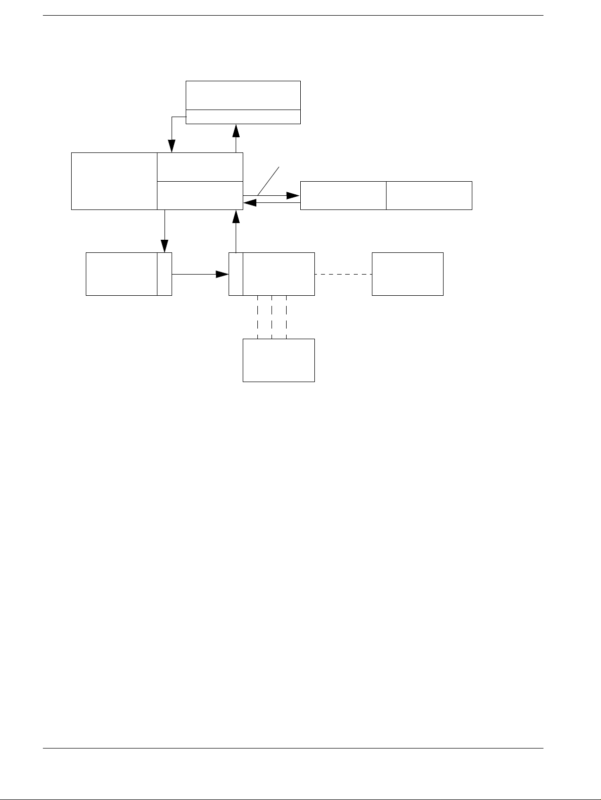
Inserting the RAS ring 1
Control station
POLYSPOT/
Primary loop
FLUOROSPOT H
RAS
Fig. 1
Sub-station
GENERATOR
Sub-station
UNIT
Methodology 1
Secondary loop 2
RAS
Sub-station
RAS RAS SEP
Sec. loop 1
R
A
S
kk-cable
R
A
S
Sub-station
KK1B
I.I./TV
Adapter
TV
SYSTEM
RWG
The RAS is a standardized interface for the components of an X-ray installation.
The RAS replaces the kk-connections. Microprocessor-controlled components exchange
information directly, r endering the kk -inte rface technology s uperfl uous. Only ti me-relevant
signals, e.g. analog signals from the Iontomat or multiplier will be forwarded via kk-connections.
The RAS network is configured as a ring (refer to the example shown in fig. 1).
Each ring is stabilized via a loop feedback. In the event of interference on the ring, the
system components linked by a secondary loop are automatically bypassed to maintain
the ring functions.
Data transfer between stations in the ring is serial via optic fiber cables.
Each RAS station consists of an RAS board or a combination of several RAS boards
depending on the system components (generator, diagnostic device ..) and their location
in the RAS network.
TV systems are connected to the network via a special interface, the I.I./TV adapter.
A kk1B connector for the I.I./TV adapter is avai lable to connect a Bucky wall stand.
RAS Register 04 RX99-051.032.02 TDRX1 Siemens AG
Rev. 01 03.95 Medical Engineering
Page 7

RAS programming for DFR systems 2
POLYSPOT/POLYTRON S PLUS 2
Setting the RAS group index:
• Connect the service PC to POLYSPOT/POLYTRON S PLUS (M80 X30).
• Start the service program ST 320.
Refer to the setting instructions POLYSPOT R41-030.032.01...
and setting instructions POLYTRON S PLUS R42-025.032.01...
• Set the RAS level index to 1 under XRAYSYSTEM/ROOM/COMMONDATA in the
Configurations menu (enter 0 Index 1).
2 - 1
FLUOROSPOT H 2
Setting the RAS group index:
• Connect the service PC to the FLUOROSPOT (Transiti on Panel J27).
• Start the service program ST 320.
Refer to the start-up instructions FLUOROSPOT RX41-020.034.01....
• Enter 1 under RAS group index on page 2 in the System Configur ation menu
Siemens AG TDRX1 RX99-051.032.02 Register 04 RAS
Medical Engineering Rev. 01 03.95
Page 8

2 - 2RAS programming for DFR systems
This page intentionally left blank.
RAS Register 04 RX99-051.032.02 TDRX1 Siemens AG
Rev. 01 03.95 Medical Engineering
Page 9
NOTICE
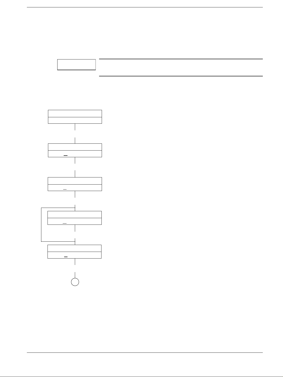
Starting up RAI I.I./TV adapter N93 3
• Connect the pocket terminal to board RAS 10. Use the same adapter board (D851) as
for POLYDOROS 50S/80S, or connect the service PC to th e pocket terminal emulation.
• Set switch S2 into position 2 (Confi g) on board RAS 10.
• Switch on the system
The label PT510 or PC on the board is without importance. Set a
baud rate of 9600 Bd when you connect a PC.
*2
3 - 1
RAS
BVFS
CR
MODE:
N
Y
MODE:
Y
CR
TV-STATION
N
Y
TV-STATION
Y
VB3
VA0
*1
JUSTAGE
Y/N
JUSTAGE
Y/N
Y/N
Y/N
*1
If errors occur during intial st art-up of the
adapter, press "CR" again.
*2
Or the actual software status
When you connect a PC, the <ENTER>key
ccorresponds to FNC, CR
Enter "Y".
(for TV configured)
CR
1
Siemens AG TDRX1 RX99-051.032.02 Register 04 RAS
Medical Engineering Rev. 01 03.95
Page 10
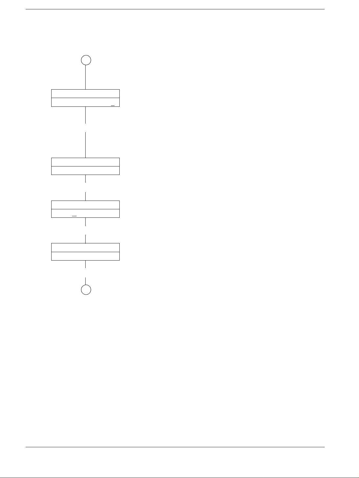
3 - 2Starting up RAI I.I./TV adapter N93
If required move cursor with "←" or"→" to the
1
GROUP-INDEX
0000000000000000
1
GROUP-INDEX
0000000000000001
digit to be changed, enter "0" or"1".
Always program
Group index 1
0000.0000.0000.0001
CR
ASSIGNMENT UNIT 1
N
Y/N
Y
ASSIGNMENT UNIT 1
YY/N
CR
2
At this point, you are programming the connection for the TV system which is always connected to unit G1 of the generator:
UNIT 1 = g1
Enter "Y" for UNIT 1.
(When you enter "Y" for "UNIT 1", the system
stops the queries for additional units).
RAS Register 04 RX99-051.032.02 TDRX1 Siemens AG
Rev. 01 03.95 Medical Engineering
Page 11

Starting up RAI I.I./TV adapter N93 3 - 3
1
TYPE HD
Y/N
N
FNC
TYPE . H
TYPE . C
TYPE . N1
TYPE . H1
TYPE . N
TYPE HPS
Y/N
N
FNC
CR
INVERT BRIGHT
N
Y/N
Y
.
.
.
.
.
TYPE HD
Y Y/N
TYPE . H
TYPE . C
TYPE . N1
TYPE . H1
TYPE . N
TYPE HPS
Y
Y Y/N
CR
Y
INVERT BRIGHT
Y
Y/N
CR
INVERT CONTRAST
Y
Y/N
CR
BV JUSTAGE
CR
CR
2
*1
*1
Brightness or contrast can be inverted as
*1
needed (depending on the system).
The following applies
TYPE HD = VIDEMED HD,
HD-Emulation
TYPE H = VIDEOMED H
TYPE N = VIDEOMED N
TYPE C = VIDEMED C
TYPE H1 = VIDEOMED H1, H1X,
H1X-Emulation
TYPE N1 = VIDEOMED N1
TYPE HPS = VIDEOMED HPS
Enter "Y" if programming was successful.
Siemens AG TDRX1 RX99-051.032.02 Register 04 RAS
Medical Engineering Rev. 01 03.95
Page 12

3 - 4Starting up RAI I.I./TV adapter N93
2
NORMAL DIAMETER
00000
mm CR
"←" bzw. "→"
0 .... 9
NORMAL DIAMETER
00330 mm CR
CR
NO ZOOM DIAMETER
00000
mm CR
CR
ZOOM1 DIAMETER
00000
mm CR
CR
ZOOM2 DIAMETER
00000
mm CR
CR
Move th cursor with "←" or "→" to the digit to be chan ged. Enter
the nominal diameter of the image intensifier in mm.
Table:
I.I.-TYPE 40-4 HD 33 HDTri. 27HD Tri.
Nom. diam. 395 mm 330 mm 278 mm
Enter the actual diameter of the image intensifier:.
Table:
I.I.-TYPE 40-4 HD 33 HDTri. 27HD Tri.
Nom. diam. 395 mm 330 mm 278 mm
Actual diam. 362 mm 304 mm 262 mm
Enter the nominal diameter of Zoom 1:
Table:
I.I.-TYPE 40-4 HD 33 HDTri. 27HD Tri.
Nom.diam. 280 mm 230 mm 170 mm
Enter the nominal diameter of Zoom 2:
Table:
I.I.-TYPE 40-4 HD 33 HDTri. 27HD Tri.
Nom. diam. 200 mm 170 mm 140 mm
ZOOM3 DIAMETER
00000
mm CR
CR
Enter the nominal diameter of Zoom 3:
Table:
I.I.-TYPE 40-4 HD 33 HDTri. 27HD Tri.
Nom. diam. 140 mm ------------- -------------
TV-STATION
OK? N
Y/N
Y
TV-STATION
OK? Y
Y/N
CR
3
RAS Register 04 RX99-051.032.02 TDRX1 Siemens AG
Rev. 01 03.95 Medical Engineering
Page 13

Starting up RAI I.I./TV adapter N93 3 - 5
3
PS = POLYSPOT
PS/PT-REM. CONT.
N
Y/N
Y
N
PT = P OLYTRON
REM. CONT. = Remote control
Enter "N" for FLUOROSPOT H.
PS/PT-REM. CONT.
Y
Y/N
CR
GROUP-INDEX
0000 0000 0000 0000
CR
GROUP-INDEX
0000 0000 0000 0001
CR
ASSIGMENT UNIT 1
N
Y/N
Y
ASSIGMENT UNIT 1
Y
Y/N
Enter "Y" in accordance with the remote control
used.
Move the cursor with "←" or "→"to the di git to be
changed. Enter "0" or "1".
Always enter
Group index 1
0000.0000.0000.0001
Since the PT/PS is connected to G1 (analogous
to the spot film device) enter "Y" for UNIT 1 if the
system is equipped with a remote control.
CR
PS/PT-REM. CONT.
OK?
N
Y/N
CR
Y
PS/PT-REM. CONT.
OK?
Y
Y/N
CR
4
Siemens AG TDRX1 RX99-051.032.02 Register 04 RAS
Medical Engineering Rev. 01 03.95
Page 14

3 - 6Starting up RAI I.I./TV adapter N93
4
BUCKY WALL UNIT
N
Y/N
Y
BUCKY
WALL UNIT
Y
Y/N
CR
EGO
N
UNIT 2
Y/N
CR
EGO
N
*1
EGO
N
UNIT 3
Y/N
CR
UNIT 4
Y/N
CR
Enter "Y" for the Bucky wall stand (connected to
kk1B of the N93).
Program "Y" for the unit (UNIT) to whi ch the Bucky
wall stand was allocated at the generator.
UNIT 6 ... 8 ( cannot be assigned, enter "N").
*1
EGO
CR
CR
UNIT 5
N
Y/N
Y
5
6
RAS Register 04 RX99-051.032.02 TDRX1 Siemens AG
Rev. 01 03.95 Medical Engineering
Page 15

Starting up RAI I.I./TV adapter N93 3 - 7
5
EGO
Y
UNIT X
Y/N
CR
GROUP-INDEX
0000000000000000
1
GROUP-INDEX
0000000000000001
CR
BUCKY
OK?
WALL UNIT
N
Y/N
6
Always enter...01 as the group index.
Enter "Y" when programming was successful.
Y
BUCKY
OK?
WALL UNIT
Y
CR
TV-STATION
Y
ESC
7
Y/N
Y/N
Siemens AG TDRX1 RX99-051.032.02 Register 04 RAS
Medical Engineering Rev. 01 03.95
Page 16

3 - 8Starting up RAI I.I./TV adapter N93
7
SAVE ALL?
N
Y/N
Y
SAVE ALL?
Y
Y/N
CR
PLEASE WAIT
CR
SAVE ALL OK?
CR
CR
MODE: NORMAL
Y/N
N
Save the programmed data with "Y".
System OFF
Disconnect service PC or PT.
RAS Register 04 RX99-051.032.02 TDRX1 Siemens AG
Rev. 01 03.95 Medical Engineering
Page 17

NOTICE
RAS-programming for the generator 4
POLYDOROS 50S/80S 4
Programming module J80
• Connect the service PC, start pocket terminal emulation and begin progr amming as
described below.
Refer to the instructions " System Configurati on POLYDOROS 50S/80S beginning with
VG1 R67-010.034.07...."
RAS J80
CR
4 - 1
CR
DISABLE RAS J80
ERROR 665
CR
GROUP-INDEX J80
00 1 ?
CR
HW-EXP-TRIGGER
UN: 1
HW-FC-TRIGGER
UN: 1
NO
CR
NO
CR
Y/N
Y/N
Y/N
When you connect a PC, the <ENTER> key corresponds to CR
Ignore the error message 665 (RAS error) up t o the next generator
OFF/ON?
Always program 001.
HW-EXP-TRIGGER (exposure):
for SEP only
YES
In all other cases
enter NO for SEP uses G3 (frontal PUCK)
G1...G5 G4 (lateral PUCK)
HW-FC-TRIGGER (fluoro):
Always enter NO
for G1...G5.
PROGRAM J80
IS OKAY CR
CR
When you program module J80 for the first time, switch OFF the
generator and then ON again to transfer and store the data.
Document the system configuration in instructions R67-
010.034.07... .
Siemens AG TDRX1 RX99-051.032.02 Register 04 RAS
Medical Engineering Rev. 01 03.95
Page 18

4 - 2 RAS-programming for the generator
POLYDOROS SX 50/80 4
Refer to the start-up instructions "Syst em configurations" to program system configurat i-
ons beginning with software version VD00A RX63-050.034... . Use the following menus:
• Configuration/Connected Components
• Configuration/RAS
• Configuration/Unit Selecti on
After completion, print out the new protocol for the system configuration. To this end, select Print in the Data menu.
File the print-out in Register 9 of the System Manual.
RAS Register 04 RX99-051.032.02 TDRX1 Siemens AG
Rev. 01 03.95 Medical Engineering
Page 19

Programming P 5/540, S 5/5-45 5
RAS expansion, D42 decision tree 5
Program according to instructions
- PANTOSKOP 5
- PANTOSKOP 540
- SIRESKOP 5
- SIRESKOP 5-45
In addition, program the followi ng:
Connect pocket terminal / PC with pocket terminal emulation to D42 in assembly M1 of
the system:
• Program the following RAS-specific dat a.
Notice:
Acknowledge memory contents with or <ENTER> for the service PC. Use
to move to the next address.
- R14-015.032.01....
- RD1-220.032.01....
- RXD1-310.032.02....
- RXD1-225.032.04....
CR
5 - 1
Overview of the decision tree D42 5
Siemens AG TDRX1 RX99-051.032.02 Register 04 RAS
Medical Engineering Rev. 01 03.95
Page 20

5 - 2Programming P 5/540, S 5/5-45
ADJUST MODE
RAS
Note:
RAS PROGRAMMED
E9A0
RAS
E9A1 + 1
RAS
E9A3
TRIGGERTIME
1
255D
150D
UNITS
XXXD
always enter 255
always enter 150
refer to page 5-3
The addresses may vary depending on the software status.
RAS Register 04 RX99-051.032.02 TDRX1 Siemens AG
Rev. 01 03.95 Medical Engineering
Page 21

Programming P 5/540, S 5/5-45 5 - 3
RAS components at the system 5
RAS
E9A3
76543210
UNITS
011D
Spot film device
Ceiling crane 2nd plane
(connected to P5/S5 )
Bucky wall stand (connected to P5/S5)
Angio tabletop with stepping
Bedside exposures (exposures without
grid start *1)
0
0
0
1 = configured
0 = not configured
• Enter 1 for configured systems
For example: P5 with spot film device, c eiling crane, Angio table with stepping .
76543210
0 0 0 0 1 101
Convert the binary value into a decimal value and enter
00001011 bin = 011D *2
under
*1 Bedside exposures:
Enter 1 if bedside exposures will be released at the X-ra y tube (e.g. 3D). The X-ray tube
will be allocated to the system and the generator in program step "UNIT 5" as well as at
the generator.
RAS
E9A3
UNITS
011D
*2 Refer to the conversion table in chapter 8.
Siemens AG TDRX1 RX99-051.032.02 Register 04 RAS
Medical Engineering Rev. 01 03.95
Page 22

5 - 4Programming P 5/540, S 5/5-45
Programming the spot film device and the ceiling crane 5
1
UNIT 1 UNIT - NO
E9A4 017D
CR
UNIT 1 ATTACHED
E9A5
000D
CR
UNIT 1 GROUP IDX
E9A6+1 00001D
CR
Notes:
Connect the spot film device to G1 at the generator. For this reason,
program 017D.
Always enter 000D.
Always enter 00001D.
UNIT 2 UNIT - NO
E..... XXXD
CR
UNIT 2 ATTACHED
E..... 000D
CR
UNIT 2 GROUP IDX
E..... 00001D
CR
2
Connecting the ceiling crane
No ceiling crane program 000D
Ceiling crane as G2 in generator program 018D
Ceiling crane as G3 in generator program 019D
Ceiling crane as G4 in generator program 020D
Ceiling crane as G5 in generator program 021D
Always enter 000D.
Always enter 00001D.
RAS Register 04 RX99-051.032.02 TDRX1 Siemens AG
Rev. 01 03.95 Medical Engineering
Page 23

Programming P 5/540, S 5/5-45 5 - 5
Programming the Bucky wall stand and ANGIO 5
2
UNIT 3 UNIT - NO
E.....
XXXD
CR
UNIT 3 ATTACHED
E.....
000D
CR
UNIT 3 GROUP IDX
E..... 00001D
CR
Notes:
Connecting the Bucky wall stand (RWG)
no RWG program 000D
RWG as G2 in generator program 018D
RWG as G3 in generator program 019D
RWG as G4 in generator program 020D
RWG as G5 in generator program 021D
Always enter 000D.
Always enter 00001D.
UNIT 4 UNIT - NO
E..... XXXD
CR
UNIT 4 ATTACHED
E..... XXXD
CR
UNIT 4 GROUP IDX
E..... 00001D
CR
3
Connecting SEP3 for systems with Angio tabletop:
no SEP program 000D
SEP3 and Angio tabletop
program 147D
configured
Notice:
Connect SEP (as G3) in the generator (PUCK frontal ) Do not use
G4 in the generator.
no Angio tabletop/SEP3 program 000D
Angio tabletop/SEP3 config. program 019D
Always enter 00001D.
Siemens AG TDRX1 RX99-051.032.02 Register 04 RAS
Medical Engineering Rev. 01 03.95
Page 24

5 - 6Programming P 5/540, S 5/5-45
Programming bedside exposures 5
UNIT 5
E.....
UNIT 5
E.....
UNIT 5
E.....
3
UNIT - NO
XXXD
CR
ATTACHED
000D
CR
GROUP IDX
00001D
CR
Notes:
Connection for bedside exposures (exposure release without grid start):
no bedside exposure: program 000D
bedside exposure as G2: program 018D
bedside exposure as G3: program 019D
bedside exposure as G4: program 020D
bedside exposure as G5: program 021D
Always enter 000D.
Always enter 00001D.
UNIT 6.......
UNIT 8
CR
PROGRAMMED
RAS
E9A0
For UNIT 6....8 program 000D.
255D
RAS Register 04 RX99-051.032.02 TDRX1 Siemens AG
Rev. 01 03.95 Medical Engineering
Page 25

Programming the SIREGRAPH D family 6
Connect pocket terminal /PC with pocket terminal emulation to Z2.K2 in M1 (refer to the
setting instructions of the r especti ve SI REGRAPH D to f ind out ho w to oper ate t he po cket
terminal).
In addition to the programming steps described in th e setting instruct ions, program the fol lowing:
RAS-Index and unit programming 6
D1, D2M D3, D340
Address Address Program
F020 H 0020 H 01 H System with RAS
F030 H 0030 H 2B H Always enter 2B
F038 H 0038 H 00 H Retrigger time RAS G, low byte
F039 H 0039 H 02 H Retrigger time RAS G, high byte
F03A H 003A H
6 - 1
76543210
0 0 0 0 10
Spot film device
0
0
Angio tabletop with stepping
Bedside ex posure
(Exposure without grid start) *1
0
0
1 = configured
0 = not configured
0
- configured devices
Example: Spot film dev. and Angio table conf.
76543210
0 0 0 0 0 101
(binary)
(hexadecimal)
*2
09
Enter 09 H in address 003A H/F03A H
Siemens AG TDRX1 RX99-051.032.02 Register 04 RAS
Medical Engineering Rev. 01 03.95
Page 26

6 - 2Programming the SIREGRAPH D family
NOTICE
*1 Bedside exposures:
Enter "1" if you want to take bedside exposures with the X-ray tube and the
exposure is to be released at the generator .
The above applies whether it is the X-ray tube of t he SIREGRAPH or the X-r ay
tube of another unit (e.g. 3D).
The X-ray tube will be allo cated later to the unit in address 004B H/ F04B H and
the generator.
This does not apply to "exposures without grid" released at the
operating console of the SIREGRAPH.
*2Refer to the binary-hexadecimal conversion table in chapter 8.
RAS Register 04 RX99-051.032.02 TDRX1 Siemens AG
Rev. 01 03.95 Medical Engineering
Page 27

Programming the SIREGRAPH D family 6 - 3
Programming the spot film device 6
D1, D2M D3, D340
Address Address Program Notes
F03B H 003B H 11 H Spot film device is connected as G1 in the gene-
rator.
F03C H 003C H 00 H Always enter 00
F03D H 003D H 01 H Group index 1
F03E H 003E H 00 H Always enter 00
Programming Angio 6
D1, D2M D3, D340
F047 H 0047 H 93 H SIREGRAPH is configured with Angio table plus step-
ping
F048 H 0048 H 13 H
14 H
F049 H 0049 H 01 H Group index1
F04A H 004A H 00 H Always enter 00
SEP3 is connected as G3 in the generator
(frontal PUCK)
SEP3 is connected as G4 in the generator
(lateral PUCK)
Programming bedside exposures 6
Program addresses 004B H (F04B H) to 004E H (F04E H) only if you programmed
"bedside exposures" for address 003A H (F03A H).
D1, D2M D3, D340
F04B H 004B H 12 H
13 H
14 H
15 H
Tube for bedside exposur es connected as G2
Tube for bedside exposur es connected as G3
Tube for bedside exposur es connected as G4
Tube for bedside exposur es connected as G5
F04C H 004C H 00 H Always enter 00
F04D H 004D H 01 H Group index 1
F04E H 004E H 00 H Always enter 00
Siemens AG TDRX1 RX99-051.032.02 Register 04 RAS
Medical Engineering Rev. 01 03.95
Page 28

6 - 4Programming the SIREGRAPH D family
This page intentionally left blank.
RAS Register 04 RX99-051.032.02 TDRX1 Siemens AG
Rev. 01 03.95 Medical Engineering
Page 29

Programming MULTIX and SEP 7
MULTIX G040G 7
Depending on the system, start up the RAS according to the start-up instructions listed
below:
MULTIX U/UH-PBL R24-036.034.03...
MULTIX UP/UPH-PBL R24-036.034.04...
MULTIX C/CH-PBL R24-036.034.07...
MULTIX CP/CPH-PBL R24-036.034.08...
Additionally, refer to R24-036.034.11....for all MULTIX C versi ons with Vertix 2E, CS4.
Additionally, refer to R24-036.034.09....for all MULTIX U versions with V erti x 2E, 2FA CS4
7 - 1
SEP 7
Use instructions R99-051.033.01 to st art-up the RAS in connection with SEP 3/90.
Siemens AG TDRX1 RX99-051.032.02 Register 04 RAS
Medical Engineering Rev. 01 03.95
Page 30

7 - 2Programming MULTIX and SEP
This page intentionally left blank.
RAS Register 04 RX99-051.032.02 TDRX1 Siemens AG
Rev. 01 03.95 Medical Engineering
Page 31

NOTICE
NOTICE
Appendix 8
Information regarding troubleshooting 8
Checking the functions of the RAS ring: 8
The functions of the RAS ring are indicated by the following green LED’s:
Board RAS 2
RAS 3
RAS 4 V3 loop 1
V4 loop 2
RAS 10 V19
RAS 10 S V13
RAS G V4
RAS M V10
RAS PC V10
These LED‘s have to be illuminated.
8 - 1
If one or more LED’s do not light up or flash only
- Check the following sources for er ror:
• respective board may b e defective
• fiber optic cable is defecti ve
• fiber optic cable is not conne cted correctly (e.g. transmit ter is connected to another
transmitter).
The RAS ring has to function even if the individual components
have not yet been configured.
Testing the functions of the system: 8
As a prerequisites, the RAS components have been programmed
as specified.
• Switch off the system
• Switch the system back on again
• The default status for the genera tor is displayed
Siemens AG TDRX1 RX99-051.032.02 Register 04 RAS
Medical Engineering Rev. 01 03.95
Page 32

8 - 2Appendix
NOTICE
The following tools are available for troubleshooting errors during switch-on or system
operation which may be caused by one of the RAS components:
• Circuit diagram RAS network X2042
• Service software RAS , instructions R99-05 1.119.01 ....
• Description of functions, RAS/RX99-051.0 41.01...chapter 5.
If you have questions regarding troubleshooting RAS components, please contact
OPSBRD: RX3HOTLINE or call 84-7773 in Erlangen.
Conversion table binary/hexadecimal values 8
Binary Decimal Hexadecimal
0000 0000
0000 0001
0000 0010
0000 0011
0000 0100
0000 0101
0000 0110
0000 0111
0000 1000
0000 1001
0000 1010
0000 1011
0000 1100
0000 1101
0000 1110
0000 1111
0001 0000
→ 00 00
→ 01 01
→ 02 02
→ 03 03
→ 04 04
→ 05 05
→ 06 06
→ 07 07
→ 08 08
→ 09 09
→ 10 0A
→ 11 0B
→ 12 0C
→ 13 0D
→ 14 0E
→ 15 0F
→ 16 10
TD RX 3 / Maierhofer
TD RX 1 / Gans-Grehl
SMS / Fear
RAS Register 04 RX99-051.032.02 TDRX1 Siemens AG
Rev. 01 03.95 Medical Engineering
 Loading...