

Page 1
PAGE 1
INSTALLATION AND USER INSTRUCTIONS - RAM1T
s
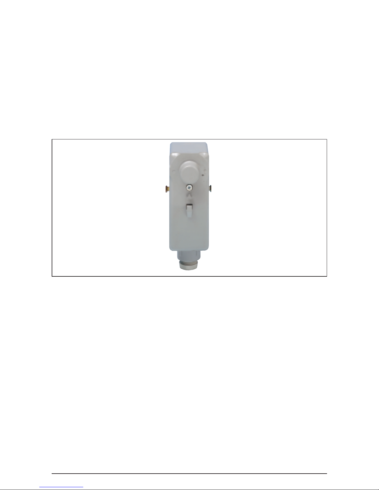
RAM1T Cylinder and/or Pipe Thermostat
Installation and User Instructions
Please note this cylinder/pipe thermostat is
capable of switching any voltage from 12 volt to
240 volt AC to a maximum amperage of 16 amps.
For wet central heating systems the fuse rating
should not exceed 3 amps!
Please also note this unit must be Earthed.
The RAM1T cylinder/pipe thermostat is a
mechanical thermostat with a bi-metallic sensor
which, under normal operation and installed in
the correct manner, is set to control with a
switching differential of 6°C. However, this is
adjustable if required between 5°C and 10°C.
The setting range of this thermostat is from 15°C
frost protection to 90°C.
Each terminal screw has its own number shown
on the plastic pillar adjacent to the screw.
Section A — Installation
To remove the cover gently prise off the control
knob and then undo the small cross-headed type
screw. Now pull the cover away from the
backplate. To replace, carry out the reverse
procedure. Adequate space has been allowed for
the connecting cables. A special cable gland is
provided at the base of the housing for securing
the cable.
When used with factory insulated hot water
cylinders, sufficient insulation must be removed
to allow the base of the thermostat to be in
contact with the cylinder wall.
The RAM1T should be mounted approx. one third
of the way up from the bottom of the cylinder and
on the opposite side to the heating coil. Each
thermostat is supplied complete with a metal
spring band, which assures a good clamping.
Page 2

PAGE 2
INSTALLATION AND USER INSTRUCTIONS - RAM1T
Wiring
1. Are you replacing an existing cylinder/pipe
thermostat?
Then follow the information in
Section (B).
2. Is this a new installation?
Then follow the
information in Section (C).
The connections to this thermostat are as shown
in the wiring diagram but for clarity note the
following:
Terminal No. 1 is the Common and receives a
signal either directly from the fuse spur or from
your HW programmer or timeswitch circuit.
Terminal No. 2 is the Normally Closed/Break on
rise (or call/on need heat) output and should be
connected to the switched live of your central
heating boiler, or the switched live of a
motorised two port zone valve.
Terminal No. 3 is the Normally Open/Make on
rise (or satisfied/off no heat) required and would
normally be connected to the offside of valves
that need power to close, or to position them;
(zone valves and 3 port mid position valves).
There is also an Earth terminal on the brass plate
and this
must be connected to a proper earth
point, to ensure continuity.
Section (B) — Replacing an existing
cylinder/pipe thermostat
Prior to carrying out any work, you must isolate
(turn off) the electrical supply to the thermostat
either at the fused spur or the mains. It is
recommended that this circuit has a maximum
of a 3 amp fuse and if not, replace with same.
Make a note of all connections, eg. Honeywell:
RED is connected to Terminal No. C; YELLOW to
Terminal No. 1; BLACK to Terminal No. 2 and so
on.
Now refer to the interchange table below and
note the new terminal numbers; eg. Landis &
Staefa RAM1T: RED will go to Terminal No. 1;
Yellow to Terminal No. 2; BLACK to Terminal No.
3. Remove the old unit and reconnect using the
new terminals plus ensuring the RAM1T is
correctly earthed.
NOTE: The colours shown above are examples
only and may have not been used in every
installation and it is advised you primarily rely
on the terminal numbers shown in the
interchange guide.
Section (C) — New installation
(or adding to an existing system)
If you are installing the thermostat to an existing
system you will need to identify the style of
system and control you are looking for and then
refer to the relevant information. Priorto carrying
out any work, you must isolate (turn off) the
electrical supply to the whole system.
Refer to the terminal numbers and note:
1.
On most current zone valve systems you will
only have to use Terminal No. 1 (common) and
Terminal No. 2 (call/on),ie. the supply from your
timer will go to Terminal No. 1 and the load (ie
pump, valve, live, etc.) to Terminal No. 2.
2.
On all current 3 port mid position systems all
three terminals will be used. Terminal No. 1
receives the LIVE; Terminal No. 2 connects to
the WHITE wire and Terminal No. 3 connects to
the GREY.
3.
If you are adding this unit to an existing older
type gravity HW system please note that
without a motorised valve with changeover
contacts the benefits will be minimal (wiring
diagrams for these style of systems are
available on application).
If you are still not sure, or having problems, then
phone the Technical Help line on 01952 602048,
open Monday to Friday (except Bank Holidays)
from 9am to 5pm.There is also an answerphone
message system in operation 24 hours a day.
Landis & Staefa RAM1 (RAM21) 1 2 3 E –
Landis & Staefa RAM2 RED BLUE GREY
– –
Drayton CS1 1 2 3 E –
Honeywell L641A C 1 2 – –
Sopac SAY C 1 2 E –
Potterton PTT1 L H C – N
Danfoss AT 1 2 3 E –
Sunvic 1452 3 1 2 E –
Sunvic SA 2451 3 1 2 E –
ACL HTS3 C 1 2 – –
ACL/Tower HTS2/CS1 RED BLK YEL – –
Randall CN4 1 2 3 E –
CylinderThermostat Interchange Guide Terminal Numbering
 Loading...