

Page 1
Building Technologies
3
01
7
Use
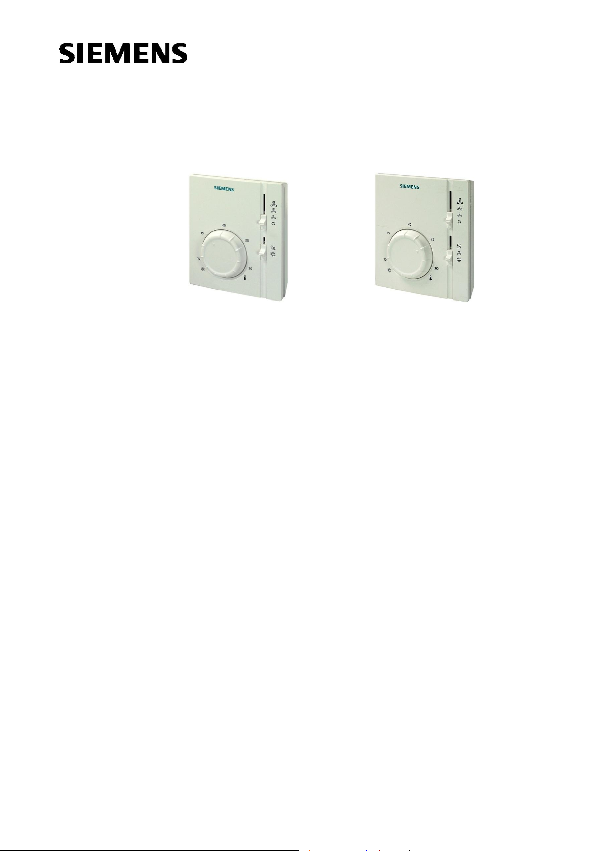
RAB 31 RAB31.1
Room Thermostats RAB31..
For four-pipe fan coils
· Room thermostat with manual switch for heating or cooling
· Two-position control
· Manual three-speed fan switch
· Switching voltage AC 24…250 V
· Control output ON/OFF
The room RAB31.. thermostat is used in heating or cooling systems to maintain the
selected room temperature.
Typical use:
· Commercial buildings
· Residential buildings
· Light industrial buildings
CE1N3017en
2015-01-07
In conjunction with
- zone valves
- thermal valves
- fans
Page 2
Functions
Heating
Cooling
Fan speed
Ventilation
Changeover
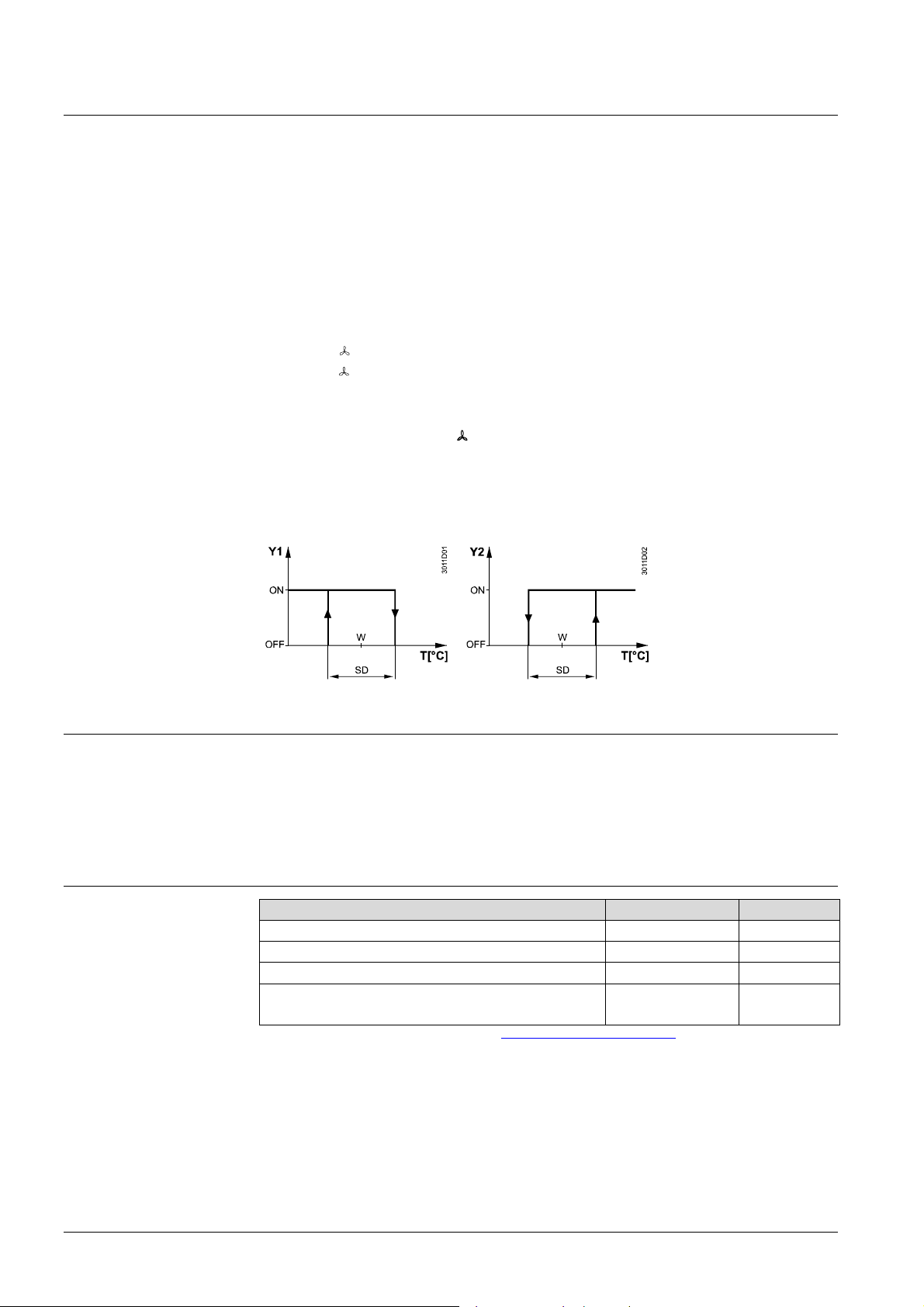
Function diagrams
If the room temperature falls below the selected setpoint, the heating contact will close.
If the room temperature exceeds the selected setpoint, the cooling contact will close.
There are two possibilities to control the fan speed:
a) Manually by means of the three - speed fan switch on the thermostat for continuous
operation
b) Automatically by switching to the selected fan speed via the thermostat for
controlled operation. In that case – prior to commissioning – the jumper positions
corresponding to the thermostat function must be selected. There are two choices of
jumper positions available on printed circuit board:
SR1
Auto
SR2
heating valve, depending on the switch position.
When the ventilation function
Selected fan speed as continuous operation
Fan is switched at the same time as the cooling or
is selected (RAB31.1) on the cover by setting the slide
switch, the heating and cooling contacts are always open and the fan operates at the
selected speed.
Heating or cooling is selected with a switch located on the front of the thermostat.
Heating Cooling
T Room temperature
SD Switching differential
W Room temperature
setpoint
Y1 Valve output signal
"Heating"
Y2 Valve output signal
"Cooling"
Type summary
Equipment combinations
Four-pipe fan coil room thermostat for use with 3-speed fan, manual
RAB31
changeover
Four-pipe fan coil room thermostat for use with 3-speed fan, manual
RAB31.1
changeover and ventilation function
Type of unit Type reference Data sheet
Motoric on/off actuator SFA21.. 4863
Thermal actuator (for radiator valve) STA21.. 4893
Thermal actuator (for small valve 2,5 mm) STP21.. 4878
Electromotoric actuator for zone valve VVI46..
(2 position on / off)
*)
The documents can be downloaded from http://siemens.com/bt/download
SUA21.. 4830
.
*)
2/6
Siemen s Room Th erm ostats RAB31.. CE1N3017en
Building Technologies 2015-01-07
Page 3

Accessories
Technical design
Adjustments
Notes
Description Type reference
Adapter plate 120 x 120 mm for 4“ x 4“ conduit boxes ARG70
Adapter plate 96 x 120 mm for 2“ x 4“ conduit boxes ARG70.1
Adapter plate for surface wiring 112x130 mm ARG70.2
Key features of the RAB31.. fan coil room thermostat:
· Two-position control
· Gas-filled diaphragm
The required temperature can be selected by a setpoint adjuster on the front of
thermostat.
The setpoint setting range can be mechanically limited by means of setpoint limiter
under the cover.
Mounting, installation
and commissioning
Warning: AC 250 V!
The thermostat should be located where the air temperature can be sensed as
accurately as possible, without getting adversely affected by direct solar radiation or
other heat or refrigeration sources.
Mounting height is about 1.5 m above the floor.
The unit can be fitted to most commercially available recessed conduit boxes or directly
on the wall.
Only authorised personnel may open the unit to perform service.
The unit must be isolated from the mains supply before opening.
When installing the unit, fix the base plate first then hook on the thermostat body and
make the electrical connections. Then fit the cover and secure it (also refer to seperate
mounting instructions).
The thermostat must be mounted on a flat wall.
The local electrical regulations must be complied with.
If there are thermostatic radiator valves in the reference room, set them to their fully
open position.
3/6
Siemen s Room Thermostats RAB31... CE1N3017en
Building Technologies 2015-01-07
Page 4

Warning!
No internal line protection for supply lines to external consumers
(Q1, Q2, Q3, Y1, Y2)
Risk of fire and injury due to short-circuits!
· Adapt the line diameters as per local regulations to the rated value of the installed
overcurrent protection device.
Maintenance
Mechanical design
Ordering
Disposal
Technical data
Power supply
Operation al data
Environmental conditions
Industry standards
Environmental
compatibility
Mechanical design
The room thermostat is maintenance-free.
The gas bellows is filled with environmentally friendly gas.
The thermostat housing is made of plastic.
Type (ASN) Part number (SSN) Description
RAB31 S55770-T229 Room thermostat RAB31
RAB31.1 S55770-T230 Room thermostat RAB31.1
The devices are considered electronics devices for disposal in term of European
Directive 2012/19/EU and may not be disposed of as domestic waste.
· Dispose of the device via the channels provided for this purpose
· Comply with all local and currently applicable laws and regulations.
Switching capacity
Voltage
Current
Frequenc y
No internal fuse
External preliminary protection with max. C 10 A circuit breaker in the supply line required under all
circumstances
Screw ter minals for 2 x 1.5 mm2(min. 0.5 mm2)
Switching differential SD £1 K
Setpoint setting range 8…30 °C
Operation
Climatic conditions
Temperature
Humidity
Pollution degree
Transport / storage
Climatic conditions
Temperature
Humidity
Mechanic al conditions
EU Conformity (CE) CE1T3015xx
RCM Conf ormity CE1T3015en_C1
Safety standard
Degree of protection of housing
The product environmental declaration CE1E3015*) contains data on environmentally
compatible product design and assessments (RoHS compliance, materials c omposition,
packaging, environmental benefit, disposal).
Weight 0.14 kg
Colour white, NCS S 0502-G (RAL 9003)
*)
The documents c an be downloaded fr om http://siemens.com/bt/download
AC 24…250 V
0.2…6 (2) A
50 or 60 Hz
to IEC 60721-3-3
Class 3K5
0…+50 °C
<95 % r.h.
normal, to EN 60730-1
to IEC 60721-3-2
Class 2K3/1K3
-20…50 °C
<95 % r.h.
Class 2M2
*)
*)
II to EN 60730-1
IP30 to EN 60529
.
4/6
Siemen s Room Th erm ostats RAB31.. CE1N3017en
Building Technologies 2015-01-07
Page 5

Connections diagram
Dimensions
D1 Zone valve or thermal valve f or heating
D2 Zone valve or thermal valve f or cooling
L Switching voltage AC 24…250 V
M1 3-speed fan
N Neutral
N1 Room thermostat
Q1 Control output
"Fan speed I", AC 250 V
Q2 Control output
"Fan speed II", AC 250 V
Q3 Control output
"Fan speed III", AC 250 V
Y1 Control output
"Valve actuator heating", AC 250 V
Y2 Control output
"Valve actuator cooling", AC 250 V
Room thermostat Base plate
Remarks
Heating:
Because of the unavoidable self heating effects of the electrical current, any loads of
more than 3 Amperes connected to the unit can influence the control behavior and
temperature accuracy in a negative way.
Cooling:
Because of the unavoidable self heating effects of the electrical current, any loads of
more than 1 Amperes connected to the unit can influence the control behavior and
temperature accuracy in a negative way.
5/6
Siemen s Room Thermostats RAB31... CE1N3017en
Building Technologies 2015-01-07
Page 6

6/6
ã
Siemens Switzerland Ltd
,
2011
Subject to change
Siemen s Room Th erm ostats RAB31.. CE1N3017en
Building Technologies 2015-01-07
 Loading...