

Page 1
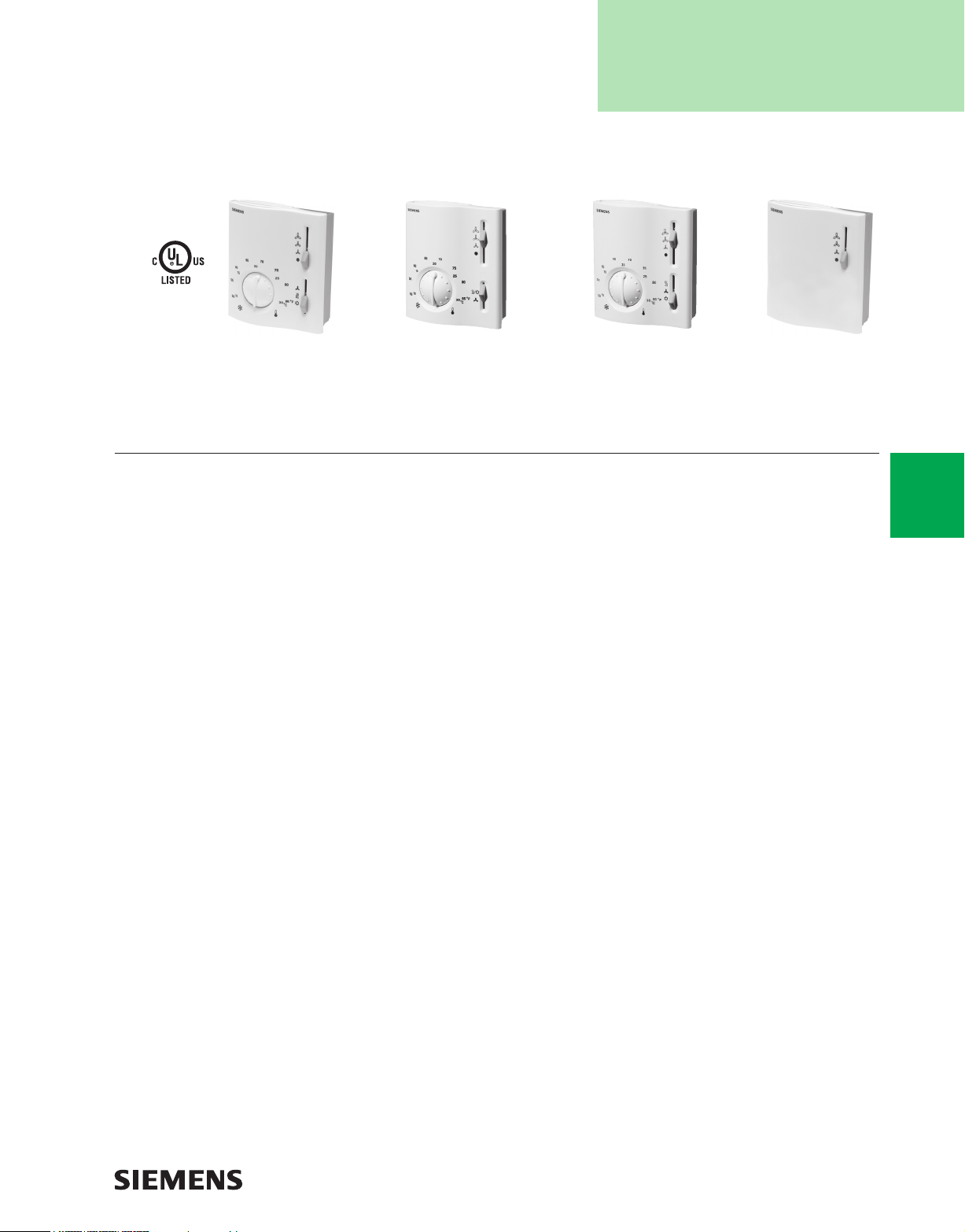
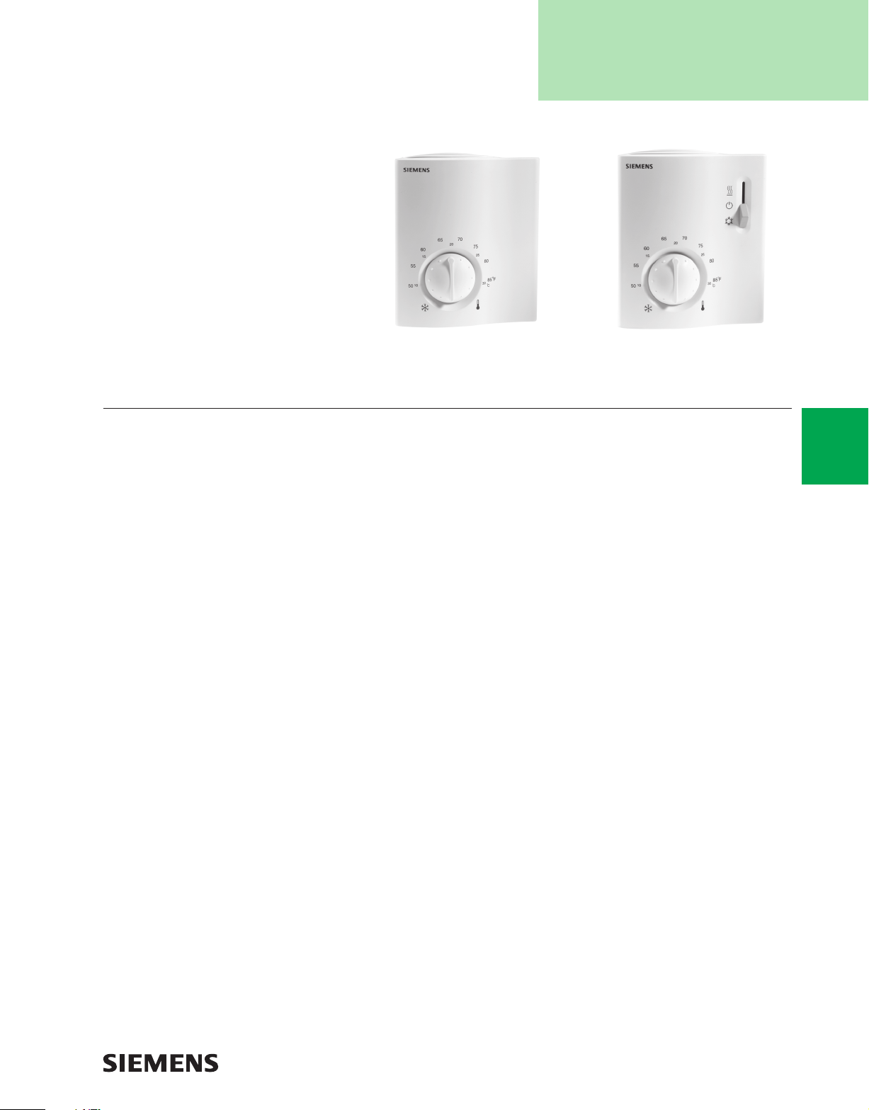
Electric Fan Coil Thermostats
RAB…
RAB10.1U Thermostat with
manual changeover.
RAB20.1U Thermostat with
exposed setpoint knob and
external changeover.
Description
Designed to control 2- or 4-pipe fan coil or unit ventilators,
the RAB… Electric Fan Coil Thermostats are an attractive
and economical solution that utilize two-wire, gas
membrane technology.
Providing On/Off control, the RAB… Electric Fan Coil
Thermostats are available with dual scale Fahrenheit/
Celsius models with manual or external changeover.
The RAB20.1U requires an aqua sensor to initiate
changeover.
Features
• Fan Speed Switch (RAB90.1U) for remote switching
location (24...277 Vac)
• Two-point control algorithm for on/off control
• Line voltage
• 2-pipe or 4-pipe fan coil applications
• 3-speed fan control
• Fan on only models for ventilation
• Manual or external changeover
• Two mounting styles: electrical wall box or drywall
• Adjustable upper/lower limit stops
• Dual Fahrenheit/Celsius scale
RAB30.1U Thermostat with
exposed setpoint knob and
3-speed fan control.
RAB90.1U 3-speed
fan switch.
Applications
The RAB… Electric Fan Coil Thermostats are
recommended for applications in commercial or light
industrial buildings in conjunction with zone valves,
thermal valves, fans or thermostats.
Note:
ARG70, wall plate, is required for UL compliance in
switching line voltage.
A-37
Thermostats
www.usa.siemens.com/hvaccomponents
Page 2

Specifi cations/Product Ordering
A-38
Operating Voltage ........................................................ 24…120, 277 Vac
Frequency ..............................................................................50 or 60 Hz
Setpoint Setting Range ....................................... 50 to 85°F (8 to 30 °C)
Switching Differential (SD) ................................................. <1.8°F (1°C)
Switch Rating ............................................... 6 A resistive, 3.5 A inductive,
Time Constant ...............................................................................14 min.
Operating Conditions
Temperature ...............................................14 to 122°F (-10 to +50 °C)
Relative Humidity ...................................................................<95% RH
Transportation Conditions
Temperature ..............................................-4 to +122°F (-20 to +50 °C)
Relative Humidity ...................................................................<95% RH
3-speed
Change- Vent- Fan Electric Wall
Application over ilation Control Switch Box1 Dry Wall
2-pipe Heating/Cooling/Ventilation Manual Yes Yes Heat/Cool/Vent RAB10.1UW RAB10.1U
RAB…
2-pipe Heating/Cooling/Ventilation Auto Yes Yes Heat/Cool/Vent RAB20.1UW RAB20.1U
4-pipe Heating/Cooling/Ventilation Manual Yes Yes Heat/Cool/Vent RAB30.1UW RAB30.1U
— 3-speed Fan Switch — — Yes — — RAB90.1U
Ordering Note
1. Includes wallplate, ARG70, to be UL compliant for switching line voltage.
3.5 FLA, 12 LRA
Description
Safety ............................................................................................. UL 873
Wiring ..........................................................Screw Terminals for Wires of
2 x 16 or 1 x 14 AWG, 20 AWG max.
Cover Color ..................................................................................... White
Shipping Weight ........................................................... 0.08 lb. (0.18 kg)
Accessories
& Service Kits
Part Nos.
A-77
Thermostats
www.usa.siemens.com/hvaccomponents
Page 3
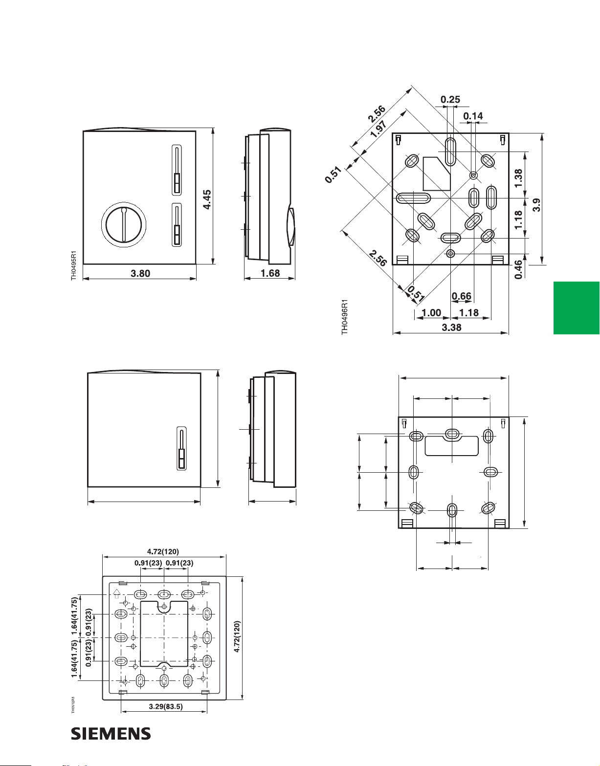
Dimensions
RAB... Room Thermostat and Wall Plate for Mounting
(RAB10.1U, RAB20.1U and RAB30.1U)
A-39
3.80
TH0721R1
(96.4)
Wall Plate (ARG70) for Mounting
RAB90.1U and Wall Plate for Mounting
3.92
(99.6)
1.53
(38.9)
(30)
1.181.18
(30)
TH0491R2
1.101.10
(28)
(28)
3.39
(86)
1.18 1.18
(30)
1.10
(28)
(30)
0.14
(3.6)
1.10
(28)
3.39
Thermostats
(86)
Dimensions shown in inches (mm).
www.usa.siemens.com/hvaccomponents
Page 4
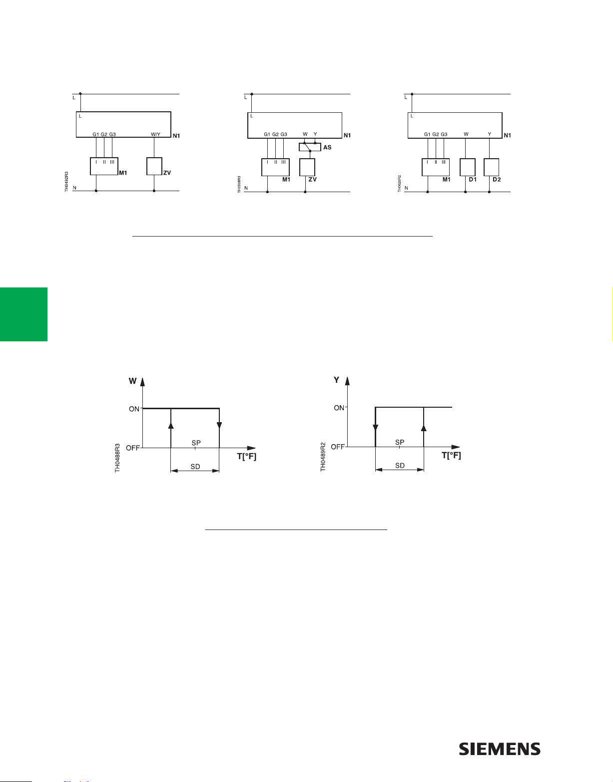
Engineering Drawings
Wiring Diagrams
A-40
Thermostats
RAB10.1U...
Key
L Operating Voltage
M1 3-speed Fan
N Neutral
N1 Room Thermostat
Heating Mode
RAB20.1U...
G1 Control Output Fan Speed I
G2 Control Output Fan Speed II
G3 Control Output Fan Speed III
Operating Diagrams
RAB30.1U...
ZV Zone or Thermal Valve
W/Y Control Output Actuator
AS Aqua Sensor
Cooling Mode
Key
T Room Temperature
SD Switching Differential
SP Room Temperature Setpoint
www.usa.siemens.com/hvaccomponents
W Valve Output Signal Heating
Y Valve Output Signal Cooling
Page 5
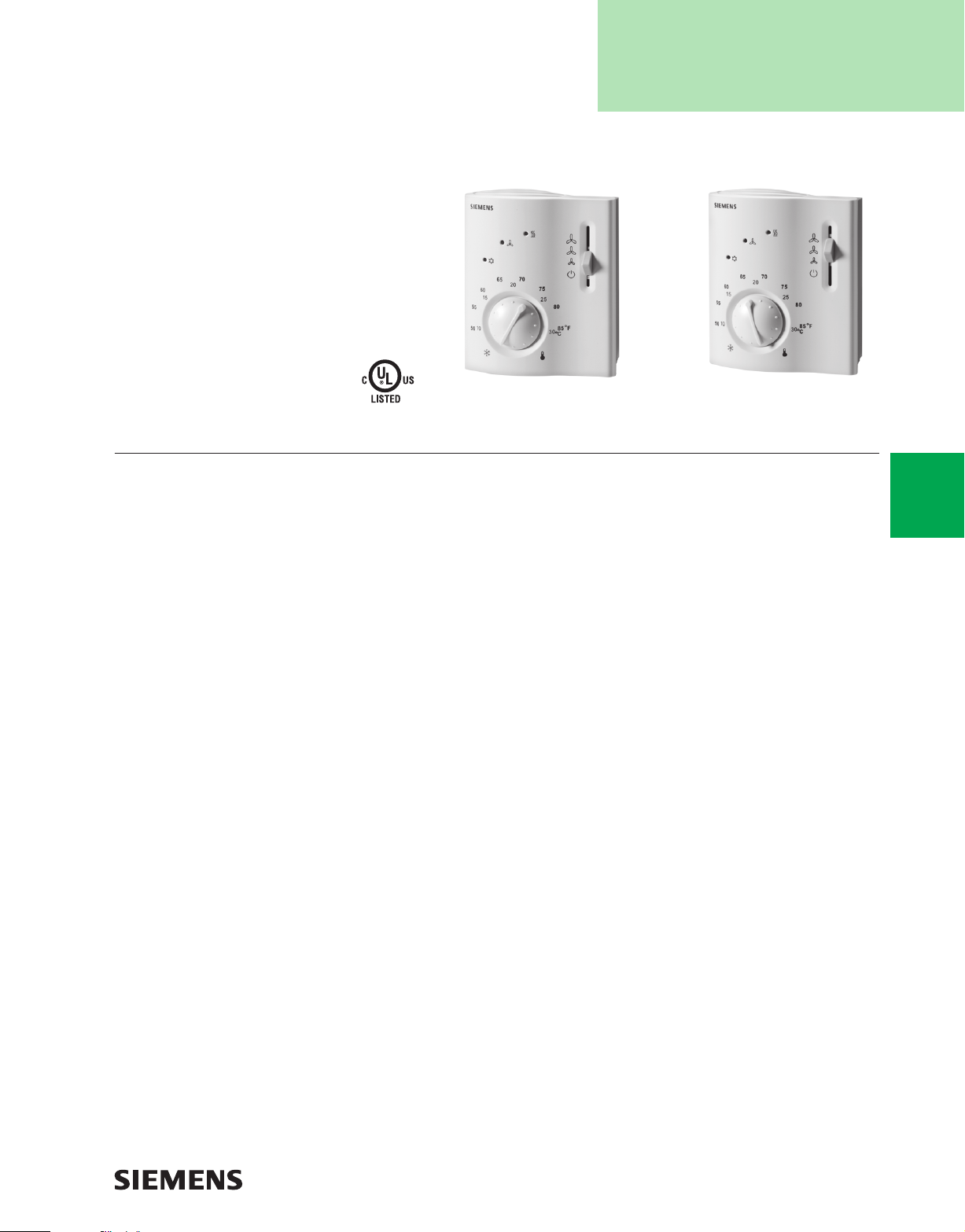
Room Temperature Controllers
for Two-pipe Fan Coil Units
RCC…
RCC20U Room Temperature Controller.RCC10U Room Temperature Controller.
Description
The RCC... Room Temperature Controllers are room
temperature controllers for two-pipe fan coil units.
Features
RCC10U
• Output for on/off valve actuator
• Output for three-speed fan
• Dual setpoint temperature scale
• Control depending on the room or return air
temperature
• Automatic Heating/Cooling changeover
• Operating modes: Normal, Energy Saving, Frost
Protection and Off
• Operating mode changeover input for remote control
• Selectable control parameters
RCC20U
• Outputs for on/off valve actuator and electrical heater.
• Output for three-speed fan.
• Dual setpoint temperature scale.
• Control depending on the room or return air
temperature (remote sensing).
• Automatic Heating/Cooling changeover.
• Operating modes: Normal, Energy Saving, Frost
Protection and Off.
• Operating mode changeover input for remote control.
• Selectable control parameters.
Applications
The RCC... Series of Room Temperature Controllers
are typically used for:
• Controlling Normally Open (NO) 120 Vac,
two-position valves.
• Controlling room temperature in individual rooms that
are heated or cooled with two-pipe fan coil units.
• Switching an electrical heater (RCC20U).
• Operating a 3-speed fan.
The RCC... Series is suitable for systems with:
• Automatic Heating/Cooling changeover.
• Heating only/Cooling only or Heating and Cooling
applications.
A-41
Thermostats
www.usa.siemens.com/hvaccomponents
Page 6
Specifi cations/Product Ordering
A-42
Operating Voltage .........................................................................120 Vac
Frequency ................................................................................... 50/60 Hz
Power Consumption ..........................................................Maximum 4 VA
Control Outputs (Fan) 11, 10, 9 ...120 Vac max./3A res./3.5 FLA/7.0 LRA
Control Output 3 ..................................................................... 0 to 10 Vdc
Resolution .................................................................................... 39 mV
Current ......................................................................................... ±1 mA
Signal Input 2 for Changeover Sensor ......................QAH11.1, Class 2,
Permissible Number of Thermostats ........ Ten in Parallel, Signal Input 3
Status Input D1 and GND
Contact Sensing ................................................... 6 to 15 Vdc/3 to 6 mA
Insulation against live voltage ......................................................... 4 kV
Operating Action ......................................................Normally Open (NO)
Permissible Cable Length with Copper
Cable 16 AWG for Connection to Signal Input 2,
D1, and GND ....................................................................... 262 feet (80m)
Setpoint Setting Range ....................................... 50 to 85°F (10 to 30°C)
Description Part No.
Two-pipe fan coil unit controller,
on/off output RCC10U
RCC...
Two-pipe fan coil unit controller with
additional electric heat; on/off output RCC20U
NTC resistor 3K Ω at 77°F (25°C)
Setpoint (Energy Saving Mode), Heating ............................ 61°F (16°C)
Setpoint (Energy Saving Mode), Cooling ............................ 82°F (28°C)
Operation
Temperature ...................................................... 32 to 122°F (0 to 50°C)
Humidity .................................................................................. <95% RH
Shipping and Storage
Temperature ............................................ –13 to +158°F (–25 to +70°C)
Humidity .................................................................................. <95% RH
Agency Approvals ......................................................................... UL 873
Certifi cation C22.2 No. 24-93
Conforms to CE Requirements
Connection Terminals .............. Solid Wires or Prepared Standard Wires
2 X16 AWG or 1 X14 AWG
Minimum 20 AWG
Housing Color
Cover .............................................................................. White and gray
Base ...............................................................................................Gray
Degree of Housing Protection .................................................... NEMA 1
Shipping Weight .............................................................. 0.5 lb. (0.23 kg)
cUL
Accessories
& Service Kits
A-77
Dimensions
Thermostats
RCC10U/20U Controller
1.38
1.10
(35)
(28)
1.18
1.10
(30)
(28)
0.46
(11.8)
TH0613R1
Dimensions are shown in inches (mm).
Baseplate
0.16 (4)
1.10
(28)
1.02
(26)
3.54
(90)
1.10
(28)
0.16
(4)
4.09
(104)
0.16 (4)
1.18
(30)
www.usa.siemens.com/hvaccomponents
Page 7
Free Energy Band™ Room Temperature
Controller for Four-pipe Fan Coil Units
RCC…
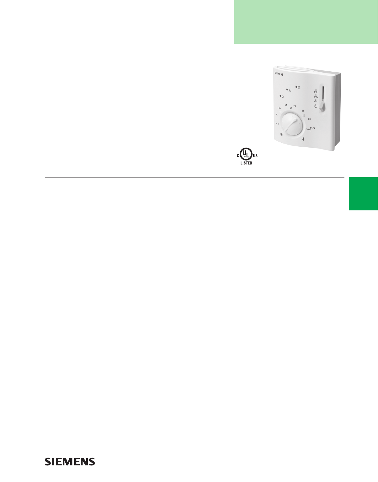
RCC30U Room Temperature Controller.
Description
The RCC... Free Energy Band Room Temperature
Controllers are room temperature controls for four-pipe fan
coil units.
Features
• Outputs for on/off valve actuators
• Outputs for three-speed fan
• Dual setpoint temperature scale
• Control depending on the room or return air
temperature (remote sensing)
• Automatic Heating/Cooling changeover
• Operating modes: Normal, Energy Saving, Freeze
Protection and Off
• Operating mode changeover input for remote control
• Selectable control parameters
• Free Energy Band between Heating and Cooling for
energy conservation
Applications
The RCC... Series is typically used for the following
applications:
• Controlling room temperature in individual rooms that
are heated or cooled with four-pipe fan coil units.
• Opening or closing a Normally Closed (NC) Heating
and a Normally Open (NO) Cooling, 120 Vac, twoposition valve.
• Switching a three-speed fan.
A-43
Thermostats
www.usa.siemens.com/hvaccomponents
Page 8
Specifi cations/Product Ordering
A-44
Operating Voltage ........................................................ 120 Vac +10/-15%
Frequency ................................................................................... 50/60 Hz
Power Consumption ...........................................................Maximum 10A
Control Outputs (Fan) 12, 11, 10
7 and 9 ....................................................................120 Vac max./3A res./
3.5 FLA/7.0 LRA
120 Vac max./3A res./3.5 FLA/7.0 LRA
Control Output 5 (Common) ..................................120 Vac/7A maximum
Signal Input 1 for Return Air Sensor ..........................QAH11.1, Class 2
NTC resistor 3K @ 77°F (25°C)
Operating Action .............................................. Single-pole, Single-throw
Permissible Cable Length with Copper
Cable 16 AWG for Connection to
Terminals 1, D1, and GND ................................................ 262 feet (80 m)
Setpoint Setting Range ....................................... 50 to 85°F (10 to 30°C)
Maximum Control Deviation at 72°F (22°C) ..... Maximum ±1.5°F (0.7°C)
Switching Differential in Heating Mode SDH
(Selectable) ..................................................................2 or 7°F (1 or 4°C)
Switching Differential in Cooling Mode SDC ..........................1 or 3.5°F
(0.5 or 2°C) (selectable)
Dead Zone in Normal Operation .............................. 3.5 or 9°F (2 or 5°C)
Description Part No.
Free Energy Band™ Four-pipe Fan
Coil Controller RCC30U
RCC... FEB
Setpoint (Energy Saving mode), Heating ............................ 61°F (16°C)
Setpoint (Energy Saving mode), Cooling ............................ 82°F (28°C)
Setpoint (Freeze Protection) .................................................. 46°F (8°C)
Operation
Temperature ...................................................... 32 to 122°F (0 to 50°C)
Humidity .................................................................................. <95% RH
Shipping and Storage
Temperature ..............................................-13 to +158°F (-25 to +70°C)
Humidity .................................................................................. <95% RH
Agency Approvals
UL Listing ....................................................................................UL 873
cUL
Certifi cation C22.2 No. 24-93
Conforms to CE requirements
Connection Terminals ................. Solid wires or prepared standard wires
2 X16 AWG or 1 X14 AWG
Minimum 20 AWG
Housing Color
Cover ............................................................................. White and gray
Base ...............................................................................................Gray
Degree of Housing Protection .................................................... NEMA 1
Shipping Weight ............................................................... 0.5 lb (0.23 kg)
Accessories
& Service Kits
A-77
Thermostats
www.usa.siemens.com/hvaccomponents
Page 9
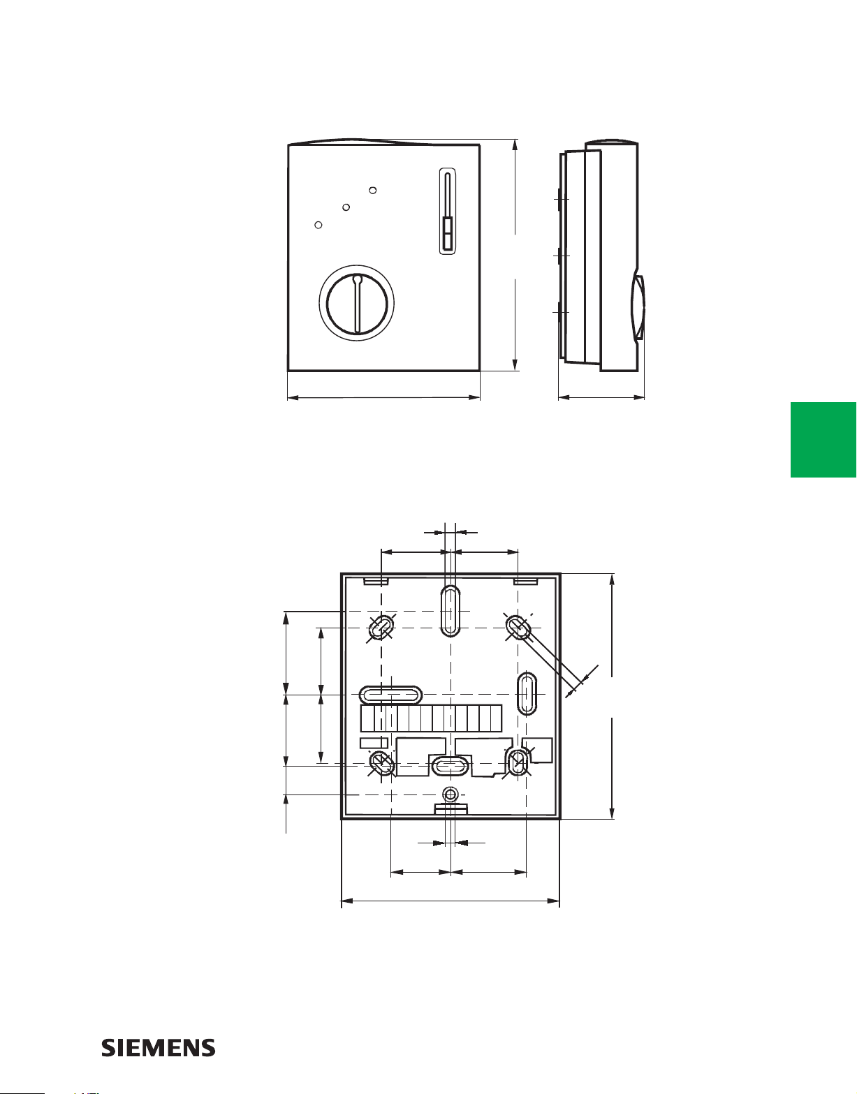
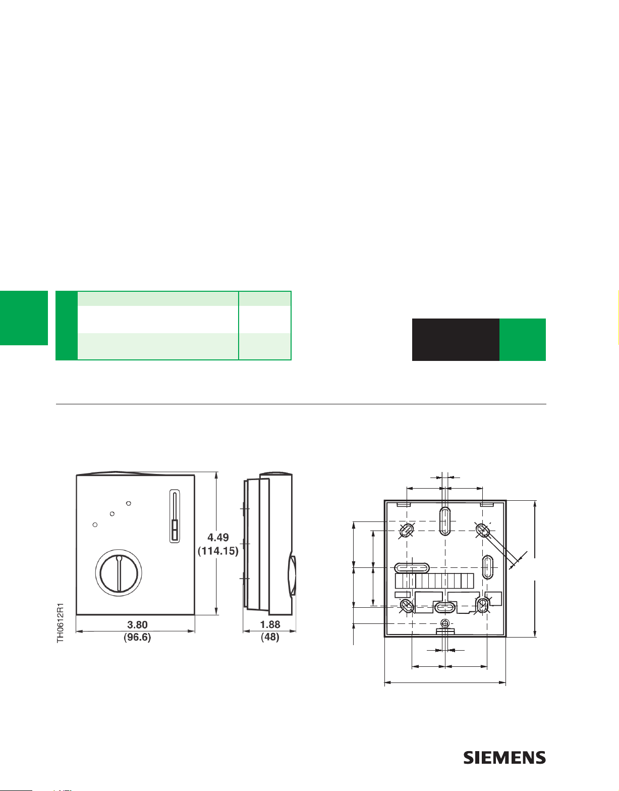
Dimensions
RCC30U FEB Controller
4.49
(114.15)
TH0612R1
1.38
(35)
1.18
(30)
1.10
(28)
1.10
(28)
3.80
(96.6)
Baseplate
0.16 (4)
1.10
(28)
1.88
(48)
A-45
Thermostats
1.10
(28)
0.16
(4)
4.09
(104)
0.46
(11.8)
TH0613R1
0.16 (4)
1.02
(26)
Dimensions shown in inches (mm).
3.54
(90)
1.18
(30)
www.usa.siemens.com/hvaccomponents
Page 10

A-46
Thermostats
TECH TIPS
Check your order status quickly and easily
via our secure Order Tracker feature. To take
advantage of time-saving benefits, go online to
www.usa.siemens.com/hvaccomponents,
click on site360, and register today.
www.usa.siemens.com/hvaccomponents
Page 11
Room Temperature Controllers
for CAV Systems
RCU15/50…
RCU15U/RCU50U
Room Temperature Controller.
Description
The RCU15/50… Series microprocessor controlled CAV
room controllers are designed for air only, or air and water
heating and/or cooling systems. Controllers have
two-position, pulse width modulation (PWM), or
proportional response.
Features
• 0 to 10 Vdc output for heating or cooling (RCU50U and
RCU50.2U)
• ON/OFF or PWM outputs for heating and cooling
(RCU15U)
• Control depending on room or return air temperature
(RCU15U)
• Automatic heating/cooling changeover (RCU15U and
RCU50U)
• Manual heating/cooling changeover (RCU50.2U)
• Operating modes: Normal, Energy Saving, Freeze
Protection and Standby (RCU15U and RCU50U)
• Operating modes: Normal and OFF (RCU50.2U)
• Active 0 to 10 Vdc input for setpoint shifting (RCU50U)
• Operating mode changeover input for remote control
(RCU50U)
• Adjustable minimum limitation for cooling output
(RCU50U)
• Operating voltage 24 Vac
RCU50.2U Room Temperature Sensor with
manual heating/cooling changeover switch.
Applications
Controlling individual room temperature in HVAC
installations that are heated or cooled.
Controlling these types of equipment:
• Valve actuators
• Air damper actuators
A-47
Thermostats
www.usa.siemens.com/hvaccomponents
Page 12
Specifi cations/Product Ordering
A-48
Power Supply
Operating Voltage ............................................................. 24 Vac ±20%
Frequency ................................................................................ 50/60 Hz
Setpoint Setting Range ...................................... 50 to 85°F (10 to 30°C)
P-band in Heating Mode
RCU50U .................................................................... 2 or 7°F (1 or 4°C)
RCU50.2U (fi xed) .................................................................... 7°F (4°C)
P-band in Cooling Mode
RCU50 ................................................................ 1 or 3.5°F (0.5 or 2°C)
RCU50.2 (fi xed) ................................................................... 3.5°F (2°C)
Setpoint (Energy Saving Mode), Heating ........................... 61°F (16°C)
Setpoint (Energy Saving Mode), Cooling ........................... 82°F (28°C)
Setpoint Freeze Protection ..................................................... 46°F (8°C)
Setpoint Shift Temperature @ 72°F (22°C) ............... +22.5°F (±12.5°C)
Control Action
RCU15U ............................................................................. On/Off/PWM
RCU50U & RCU50.2U ........................................................ Proportional
Control Outputs, Terminals 4 and 5 (RCU 50...)
Voltage ................................................................................. 0 to 10 Vdc
Current ......................................................................................... ±1 mA
Control Outputs, Terminals 7 and 8 (RCU15U) ........... PWM or ON/OFF
Voltage .............................................................................. 24 Vac ±20%
Current ................................................................................... 0.02 to 1A
Cycle time PWM (selectable for terminal 7) ...........................20s or 90s
Status Input D1 (RCU50U)
Contact sensing ................................................... 6 to 15 Vdc/3 to 6 mA
Insulation against live voltage ......................................................... 4 kV
Maximum number of contacts connected in a panel .......................... 50
Status Inputs 1 and 2 (RCU50U)
Setpoint shift of +22.5°F @ 72°F (22°C) .............................. 0 to 10 Vdc
Neutral position (no setpoint shift) ................................................. 5 Vdc
Signal Input Terminals 2 and 3
for Changeover Sensor ....................................... QAH11.1 safety class 2
NTC resistor 3KΩ @ 77°F (25°C)
Maximum Copper Cable Length 16 AWG
For Input Signal terminals 1 & 2 (RCU50U) .................... 262 feet (80m)
For Input Signal D1 (RCU50U) ....................................... 262 feet (80m)
Operation
Temperature ...................................................... 32 to 122°F (0 to 50°C)
Humidity .................................................................................. <95% RH
Shipping and Storage
Temperature ..................................................-13 to 158°F (-25 to 70°C)
Humidity .................................................................................. <95% RH
Agency Approvals .......................................................... UL listed UL 873
Conforms to CE requirements
cUL certifi ed to Canadian Standard C22.2 No. 24-93
Connection Terminals ....... Use Solid Wires or Prepared Stranded Wires
2 x 16 AWG or 1 x 14 AWG, 20 AWG max.
Housing Color
Cover ............................................................................................. White
Base ...............................................................................................Gray
Shipping Weight ............................................................... 0.5 lb (0.23 kg)
Heat/Cool Changeover Output(s) Part No.
Automatic (2) On/Off or PWM RCU15U
Automatic (1) 0 to 10 Vdc RCU50U
RCU15/50…
Manual (1) 0 to 10 Vdc RCU50.2U
Thermostats
Ordering Note: The temperature sensor, changeover mounting
kit, and valve and damper actuators must be ordered separately,
see table below.
Device Combinations
Description Part No.
Remote Cable
Temperature/Changeover Sensor QAH11.1
44 lb-in NSR Air Damper Actuator GDE16...
88 lb-in NSR Air Damper Actuator GLB16...
Valve Actuator SSB61U
Valve Actuator SSC61U
SSC61.5U
Valve Actuator SQS65U
SQS65.5U
www.usa.siemens.com/hvaccomponents
Page 13

Engineering Drawings
Function Diagrams
Y1[%]
100
0
XpH
TH0904R1
SDH SDC
RCU15U – Heating-Cooling
Key
T Room temperature
Y1, Y2 Output percentage
W Room temperature setpoint
Xdz Dead band
XpH Proportional band heating
2 P
W
Xdz
XpK
XpK Proportional band cooling
SDH Switching differential for heating
SDC Switching differential for cooling
2 P. 2-position outputs
Y2 [%]
100
T [∞F]
A-49
Thermostats
RCU50U – Heating-Cooling with Minimum Limitation Cooling
Key
T Room temperature
Y10 Output percentage
W Room temperature setpoint
XpH Proportional band heating
XpK Proportional band cooling
VR 0 to 100% minimum limitation of
cooling output
c/o Changeover
RCU50.2U – Heating-Cooling
Key
T Room temperature
Y10 Output percentage
W Room temperature setpoint
XpH Proportional band heating
XpK Proportional band cooling
c/o Changeover
www.usa.siemens.com/hvaccomponents
Page 14

A-50
Dimensions
RCU15/50… Controller
Thermostats
RCU15/50… Baseplate
Dimensions shown in inches.
www.usa.siemens.com/hvaccomponents
Page 15

Room Temperature Controllers
for CAV and VAV Systems
RCU61U
RCU61U Room Temperature Controller.
Description
The RCU61U Room Temperature Controllers are designed
specifi cally for Constant Air Volume and Variable Air
Volume Systems.
Features
• Modulating P-control
• 0 to 10 Vdc output for cooling
• Three-position output 24 Vac for heating
• Operating modes: normal, energy saving and standby
• Active 0 to 10 Vdc input for remote setpoint shifting
• Operating mode changeover input for remote control
• Adjustable minimum limitation for cooling output
• Operating voltage 24 Vac
• Ergonomic design
• Dual Fahrenheit/Celsius scale
Applications
Controlling individual room temperature in HVAC
installations that are heated or cooled, the RCU61U
Temperature Controllers are suited for use with VAV
systems with auxiliary heating with VAV compact
controllers, valve actuators, and air damper actuators.
Function Diagram
A-51
Thermostats
Key
T Room Temperature
Y2, Y10 Output Percentage
W Room Temperature Setpoint
XpH Proportional Band Heating
www.usa.siemens.com/hvaccomponents
XpK Proportional Band Cooling
VR 0 to 100% Minimum Limitation
of Cooling Output
Page 16

Specifi cations/Product Ordering
A-52
Power Supply
Operating Voltage ............................................................. 24 Vac +10%
Frequency ................................................................................ 50/60 Hz
Setpoint Setting Range ........................................ 46 to 86°F (8 to 30°C)
Maximum Control Deviation at 68°F (20°C) ................................. +0.7 K
Switching Differential Heating SDH
or P-band XpH (Selectable) .......................................2 or 7°F (1 or 4°C)
Switching Differential Cooling SDC
or P-band XpC (Selectable) .................................1 or 3.5°F (0.5 or 2°C)
Setpoint Shift Temperature @ 72°F (22°C) ...................... +22.5°F (+°C)
Control Outputs (Cooling) 4 & 5 ........................................... 0 to 10 Vdc
Voltage .........................................................................................24 Vac
Current ......................................................................................... +1 mA
Control Outputs (Heating) 8, 9 &10 .................................... 24 Vac ±20%
Motor Timing for Heat Output .....................................150 sec. @ 60 Hz
Status Input D1
Contact Sensing .................................................. 6 to 15 Vdc /3 to 6 mA
Insulation Against Live Voltage ....................................................... 4 kV
Maximum Number of Contacts per Panel .......................................... 50
Description Part No.
Room Temperature Controller RCU61U
RCU61U
Status Input B1
Setpoint Shift of 36°F (12.5 C) ............................................. 0 to 10 Vdc
Neutral Position (No Setpoint Shift) .............................................. 5 Vdc
Signal Input B2 for Changeover Sensor ..........QAH11.1 Safety Class 2
Maximum Copper Cable Length 16 AWG
For Input Signal B1/B2 (RCU61U) ....................................262 ft. (80 m)
For Input Signal D1 (RCU61U) ......................................... 262 ft. (80 m)
Operation
Temperature ...................................................... 32 to 122°F (0 to 50°C)
Humidity .................................................................................. <95% RH
Agency Listings ............ UL Listed 197N; Conforms to CE Requirements
Connection Terminals ...... Use Solid Wires or Prepared Stranded Wires
2x13 AWG or 1x16 AWG
Housing Color
Cover ............................................................................................. White
Base ...............................................................................................Gray
Shipping Weight ............................................................. 0.5 lb. (0.02 kg)
Accessories
& Service Kits
A-77
Thermostats
Device Combinations
Description Type Reference
Valve Actuator SSA81
SSB61U
SSB81
SSC81
Damper Actuator GLB16x
GCA16x
GBB16x
GDE16x
www.usa.siemens.com/hvaccomponents
Page 17

Dimensions
RCU61U Controller
A-53
Baseplate
Thermostats
Dimensions shown in inches.
www.usa.siemens.com/hvaccomponents
Page 18

A-54
Thermostats
TECH TIPS
Check your order status quickly and easily
via our secure Order Tracker feature. To take
advantage of time-saving benefits, go online to
www.usa.siemens.com/hvaccomponents,
click on site360, and register today.
www.usa.siemens.com/hvaccomponents
Page 19

RLA162.5U
Room Temperature Controller
with Two 0 to 10 Vdc Outputs
Description
Room temperature controller for basic ventilation,
air conditioning and heating systems. Compact design
with two analog, 0 to 10 Vdc control outputs for heating
and/or cooling, and digital input for pump or fan.
Features
• Automatic heat/cool changeover.
• Automatic day/night setpoint changeover via
external contact.
• Room temperature control through modulating control
of valve or damper actuators with selectable operating
action of control signals for heating only, cooling only,
or heating and cooling in sequence.
• Relay input for fan pump or other controls.
• Minimum limitation of the supply air temperature.
• Outputs are independently selectable direct acting (DA)
or reverse acting (RA).
• Adjustable proportional band.
New!
RLA162.5U Room Temperature Controller
Applications
• Single-stage heating
• Single-stage cooling
• Two-stage heating
• Heating and cooling in sequence
• Minimum limitation of supply air
Devices that can be controlled:
• Modulating heating or cooling valve actuators
• Modulating air damper actuators
• Circulating pumps, charging pumps, and boilers
A-55
Thermostats
www.usa.siemens.com/hvaccomponents
Page 20

Specifi cations/Product Ordering
A-56
Power Supply
Operating Voltage .......................................................24 Vac ±20/-25%
Frequency ................................................................................ 50/60 Hz
Power Consumption ........................................................Maximum 2 VA
Setpoint Temperature Differential
Adjustment Range ................................................. 46 to 86°F (8 to 30°C)
Night Setpoint Differential From
Day Setpoint, Adjustable ......................................... 0 to 18°F (0 to 10 K)
Proportional-band ....................................................2 to 90°F (1 to 50 K)
Integral Action Time with PI Control ............. 600 Seconds (10 minutes)
Dead Zone with Heating/Cooling in Sequence ..................... 1.8°F (1 K)
Relay Input (Fan) 13, 20 .................................................................24 Vac
Control Outputs 18, 19, Modulating, P or P + I Control Algorithm
Voltage ...................................................... 0 Vdc to 10 Vdc, Continuous
Current ...........................................................................Maximum 1 mA
Maximum Cable Length Copper (16 AWG)
For Signal Input 5, 11 ..................................................... 262 feet (80 m)
Contact Input (D1-GND) ............................................................ 3 to 6 mA
Description Part No.
Room Temperature Control with
Minimum Limitation and Automatic
Day/Night Changeover RLA162.5U
RLA162.5U
Ordering Note: The temperature sensor, kit, and valve and
damper actuators must be ordered separately, see table below.
Operation
Temperature ...................................................... 32 to 122°F (0 to 50°C)
Humidity .................................................................................. <95% RH
Transport
Temperature ..................................................-13 to 158°F (-25 to 70°C)
Humidity .................................................................................. <95% RH
Regulatory Approvals
Degree of protection .................................................................. NEMA 1
UL listing ...................................................................................... UL 916
cUL ................................... Canadian Standard C22.2 No. 205-M1983
Connection Terminals for solid wires
or stranded wires .......................................... 2 x 16 AWG or 1 x 14 AWG
Sensor
Sensing Element ............................... Siemens-Ni 1000 Ω at 32°F (0°C)
Shipping Weight ............................................................. 1.40 lb (0.64 kg)
Wiring Diagrams
Thermostats
Device Combinations
Actuators and controls must meet the following specifi cations:
• Operating voltage 24 Vac
• Control input: modulating 0 to 10 Vdc
Description Type Reference
OpenAirTM GDE Series Damper Actuator GDE161.1T
with 44 lb/in torque GDE161.1P
TM
OpenAir
with 88 lb/in torque GLB161.1P
OpenAir
62 lb/in torque GMA161.1U
Accessory wall escutcheon ARG70
Air duct temperature controller
(as a minimum limiter) RLM162U
Cable changeover sensor QAP22
GLB Series Damper Actuator
TM
GMA Damper Actuator GMA161.1P
RLA162.5U
Key
B2 Heat/cool changeover sensor
E1 Fan or auxiliary unit
F2 Low temperature detection thermostat
N1 Room temperature controller (RLA162.5U)
S1 Time clock or switch for day/night setpoint changeover
Y1 Heating valve actuator
Z9 Limit controller (RLM162U) as a limiter
www.usa.siemens.com/hvaccomponents
Page 21

Engineering Drawings
Function Diagrams
RLA162.5U Room Temperature Controller
A-57
RLA162.5U and RLM162U Room Temperature Controllers
Key
N1 Room Temperature Controller (RLA162.5U)
N2 Air Duct Temperature Controller (RLM162U) — controls minimum or maximum limitation of discharge air
Y1 Heating valve
Y2 Cooling valve
Thermostats
www.usa.siemens.com/hvaccomponents
Page 22

A-58
Dimensions
RLA162.5U Controller
Thermostats
RLA162.5U Baseplate
Dimensions shown in inches (mm).
www.usa.siemens.com/hvaccomponents
Page 23

Room Temperature Controllers
with LCD for Heating
and Cooling Systems
RDU...
Description
The RDU Series Room Controller with LCD is designed for
2-pipe heating and cooling systems.
Features
• Liquid crystal display
• Modulating Proportional + Integral (P+I) control
• Control depending on room or remote air temperature
• Output for a 0 to 10 Vdc actuator (RDU50U and
RDU50.2U)
• Output for a fl oating (3-position) or on/off output
actuator (RDU20U)
• Adjustable actuator run time (RDU20U)
• Automatic heating/cooling changeover (RDU20U
and RDU50U)
• Manual heating/cooling changeover (RDU50.2U)
• Operating modes: Normal, Energy Saving and Off
(RDU20U and RDU50U)
• Operating mode changeover input for day/night
remote control
• Selectable installation and control parameters
• Adjustable minimum limitation for cooling output
(RDU50U)
• Optional selectable Direct Acting or Reverse Acting
output (RDU50U and RDU50.2U)
• Selectable display of room temperature or setpoint
• Fahrenheit or Celsius selectable display
• Minimum and maximum setpoint limitation
• Operating voltage, 24 Vac
RDU20U/RDU50U Room
Temperature Controller.
RDU50.2U Room
Temperature Controller.
Applications
The RDU…Series of Room Temperature Controllers are
used for individual room temperature control in heating or
cooling HVAC applications.
A-59
Thermostats
www.usa.siemens.com/hvaccomponents
Page 24

Specifi cations/Product Ordering
A-60
Operating Voltage ................................................................ 24 Vac +20%
Frequency ................................................................................... 50/60 Hz
Power Consumption ..........................................................Maximum 4 VA
Control Output 1–5 (RDU50U and RDU50.2U) ..................... 0 to 10 Vdc
Resolution .................................................................................... 39 mV
Effective Current ...........................................................Maximum +1 mA
3-position Control Output 4–6 (RDU20U) .....................................24 Vac
Return air temperature input 4–3 ......................QAH11.1 Safety Class 2
Changeover temperature input
2–3 (RDU50U)
8–7 (RDU20U) ...................................NTC resistor 3K ohm at 77°F (25°C)
Dry Contact D1 and GND
Contact Sensing ................................................... 6 to 15 Vdc/3 to 6 mA
Operating Action .....................................................Normally Open (NO)
Maximum Cable Length 16 AWG for Connection
to Terminals 4, 2 and D1 .................................................. 262 feet (80 m)
Setpoint Setting Range ......................................... 41 to 95°F (5 to 35°C)
Control Deviation at 77°F (25°C) ......................Maximum ±1.6°F (0.9°C)
Description Part No.
Automatic heating/cooling changeover,
3 Position RDU20U
Automatic heating/cooling changeover,
RDU...
0-10Vdc RDU50U
Manual heating/cooling changeover
switch, 0-10Vdc RDU50.2U
P-band in Heating Mode, Adjustable
in 0.5K Increments (1 Kelvin = 2°F) .........................................0.5K to 4K
Factory Setting ................................................................................... 2K
P-band in Cooling Mode, Adjustable
in 0.5K Increments (1 Kelvin = 2°F) .........................................0.5K to 4K
Factory Setting ................................................................................... 1K
Integral Action Time, Adjustable .....................................1 to 10 Minutes
Factory Setting ........................................................................ 5 Minutes
Setpoint (Energy Saving Mode), Heating ............. 41 to 65°F (5 to 18°C)
Setpoint (Energy Saving Mode), Cooling ........... 75 to 95°F (24 to 35°C)
Operation
Temperature ...................................................... 32 to 122°F (0 to 50°C)
Humidity .................................................................................. <95% RH
Shipping and Storage
Temperature
(RDU50U and RDU50.2U) .......................-13 to 158°F (-25 to 70°C)
(RDU20U) ................................................. -13 to 140°F (-25 to 60°C)
Humidity .................................................................................. <95% RH
Agency Approvals ................................... Conforms to CE Requirements
NEMA 1
Connection Terminals ...... Use Solid Wires or Prepared Stranded Wires.
2 x 16 AWG or 1 x 14 AWG
Maximum 20 AWG
Housing Color
Cover ............................................................................................. White
Base ...............................................................................................Gray
Shipping Weight ............................................................... 0.5 lb (0.23 kg)
Device Combinations
Thermostats
Description Type Reference
0 to 10 Vdc Valve Actuators SSB61U…
SSC61U…
SQS65U
SSC61.5U
SQS65.5U
44 lb-in NSR Air Damper Actuators GDE16…
RDU50U and RDU50.2URDU20UAll Models
88 lb-in NSR Air Damper Actuators GLB16…
Floating Control Valve Actuators SSB81U…
SSC61U
SSC81U
SQS65.5U
44 lb-in NSR Air Damper Actuators GDE131…
88 lb-in NSR Air Damper Actuators GLB131…
Two-way Globe Zone Valves Powermite MZ Series
Three-way Globe Zone Valves Powermite MZ Series
Two-way Globe Zone Valves Powermite MT Series
Three-way Globe Zone Valves Powermite MT Series
Two-way Ball Valves Powermite 599 Series
Accessories
& Service Kits
A-77
www.usa.siemens.com/hvaccomponents
Page 25

Dimensions
RDU...Controller
4.61
(117)
TH0769R1
4.21
(107)
1.77
(45)
3.78
(96)
Baseplate
1.10
(28)
1.10
(28)
0.16
(4)
0.46
(11,8)
1.10
(28)
1.10
(28)
1.38
(35)
A-61
Thermostats
TH0772R1
0.16 (4)
1.18
(30)
Dimensions shown in inches (mm).
0.98
(25)
3.54
(90)
www.usa.siemens.com/hvaccomponents
0.28
(7)
Page 26

A-62
Thermostats
TECH TIPS
Visit us on the web at:
www.usa.siemens.com/hvaccomponents,
for printable product specification sheets on all
products in this catalog.
www.usa.siemens.com/hvaccomponents
Page 27

Room Temperature Controller
with LCD
RDX...
RDX42.22U Room Temperature
Controller with LCD.
Description
The RDX... Room Temperature Controller with LCD is a
controller for heat pump systems with reversing valve, or
standard heating and cooling with optional electric heater,
one- or two-stage heating and one-stage cooling.
Features
• Outputs for one-stage compressor and reversing valve
or on/off valve actuators
• Output for auxiliary electric heating
• Output for a one-speed fan
• Room or return air temperature control
• Manual heating/cooling changeover
• Operating modes: Normal (heating, cooling), Energy
Saving, Off
• Operating mode changeover input for remote control
• Selectable installation and control parameters
• Operating voltage 24 Vac
Applications
The RDX... Series of Room Temperature Controllers are
used for control of the following:
• Heat pump systems with reversing valve, optional
electric heater, one- or two-stage heating and
one-stage cooling.
• Four pipe standard heating and cooling systems.
• Room temperature in individual rooms that are heated
or cooled with four-pipe fan coil units and optional
electric heating.
• Opening and closing a valve.
• Switching a one-speed fan.
A-63
Thermostats
www.usa.siemens.com/hvaccomponents
Page 28

Specifi cations/Product Ordering
A-64
Operating Voltage ................................................................ 24 Vac ±20%
Frequency ................................................................................... 50/60 Hz
Power Consumption ..........................................................Maximum 6 VA
Control Output FAN ........................................................................24 Vac
Rating ............................................................................ Maximum 5(3)A
Control Outputs Cooling and Heating ..........................................24 Vac
Rating ............................................................................ Maximum 5(3)A
Control Output Aux. Heating .........................................................24 Vac
Rating ............................................................................ Maximum 5(3)A
Remote Temperature Sensor
Status Input 8-7 ...................................................QAH11.1 Safety Class II
NTC resistor 3 k ohm at 77°F (25°C)
Status input D1 and GND
Operating Action Selectable ..................................... Normal Open (NO)
Contact Sensing ..................................................... Normal Closed (NC)
Insulation Against Line Voltage ..........SELV 6 to 15 Vdc/3 to 6 mA, 4kV
Reinforced Insulation
Permissible Cable Length with Copper Cable
2 X16 AWG or 1 X14 AWG for Connection to
Terminals 8 and D1 .............................................................. 262 ft. (80 m)
Description Part No.
Room Temperature Controller RDX42.22U
RDX...
Setpoint Setting Range ......................................... 46 to 95°F (8 to 35°C)
Control Deviation at 77°F (25°C) ........................ Maximum + 1°F (0.5 K)
Setting Range ................................................................ Factory Setting
Switching Differential in Heating Mode (adj) .....1 to 7°F 3.5°F (2 K)
Switching Differential in Cooling Mode (adj) ..... 1 to 7°F 2°F (1 K)
Setpoint Differential WD (Adjustable) .................1 to 9°F 3.5°F (2 K)
Setpoint (Energy Saving Mode), Heating ....... 46 to 64°F 61°F (16°C)
Setpoint (Energy Saving Mode), Cooling .......75 to 95°F 82.5°F (28°C)
Operation
Temperature ...................................................... 32 to 122°F (0 to 50°C)
Humidity .................................................................................. <95% RH
Shipping and Storage
Temperature ..............................................-13 to +158°F (-25 to +70°C)
Humidity .................................................................................. <95% RH
Agency Approvals ................................... Conforms to CE Requirements
NEMA 1
Connection Terminals .................................................Use Solid Wires or
Prepared Stranded Wires. 22 AWG to 14 AWG
Housing Cover Color ....................................................................... White
Shipping Weight ............................................................ 0.5 lb. (0.225 kg)
SP
QAH11.1
Thermostats
B1
498 D1GND
24 Vac
112 5 2 10
5(3)A
SN
TH0873R2
Key
6 Cooling output NC contact
5 Cooling output NO contact
11 Heating output NC contact
9 Heating output NO contact
max.
RDX… Four-pipe System Wiring
611
5(3)A
max.
5(3)A
max.
37
5(3)A
max.
Wiring Diagrams
SP
24 Vac
SN
TH0874R1
QAH11.1
B1
498 D1GND
112 5 2 10
61137
5(3)A
max.
5(3)A
max.
5(3)A
max.
RDX… Heat Pump Wiring
Key
6 Cooling output NC contact for reversing valve
5 Cooling output NO contact for compressor
11 Heating output NC contact for reversing valve
9 Heating output NO contact for compressor
Note: Outputs 5 and 10 must be wired together for compressor control
5(3)A
max.
www.usa.siemens.com/hvaccomponents
Page 29

Dimensions
RDX... Controller
4.33 (117)
4.21
(107)
TH0870R1
1.77
(45)
3.78 (96)
1.10
(28)
Baseplate
1.10
(28)
(4)
0.16
1.38
(35)
A-65
Thermostats
0.46
(11,8)
1.10
(28)
1.10
(28)
TH0772R1
0.16 (4)
1.18
(30)
Dimensions shown in inches (mm).
0.98
(25)
3.54
(90)
www.usa.siemens.com/hvaccomponents
0.28
(7)
Page 30

A-66
Thermostats
TECH TIPS
Visit us on the web at:
www.usa.siemens.com/hvaccomponents
You can:
• search for products by part number
or description.
• print out product information for submittals.
• link to technical documentation.
• locate a distributor near you.
www.usa.siemens.com/hvaccomponents
Page 31

RDF
Room Temperature Controllers
with LCD for Two-Pipe Fan Coil Units
Description
Room temperature controller with LCD for two-pipe fan
coil units.
Features
RDF10U
• Output for an on/off valve actuator
RDF20U
• Output for an on/off valve actuator and an electric heater
RDF50.1U
• Modulating PI control
• Output for a 0 to 10 Vdc valve actuator
RDF60.1U
• Modulating PI control
• Output for a three-position valve actuator
ALL MODELS
• Outputs for a three-speed fan
• Control depending on the room or the return
air temperature
• Automatic heating/cooling changeover
• Continuous heating or cooling mode
• Operating modes: Normal, Economy and Standby
• Operating mode changeover input for remote control
(Day/Night)
• Air movement control function for avoiding damage
resulting from moisture
• Selectable installation and control parameters
• Display of room temperature or setpoint (selectable)
• Electronic minimum and maximum setpoint limits
• Operating voltage 24 Vac
Applications
Typical use for RDF10U:
• Control of the room temperature in individual rooms that
• Opening or closing a valve and switching a three-
Typical use for RDF20U:
• Control of the room temperature in individual rooms
• Opening or closing a valve, switching a three-speed fan,
Typical use for RDF50.1U:
• Control of the room temperature in individual rooms that
• For opening and closing a 0 to 10 Vdc valve operating
Typical use for RDF60.1U:
• Control of the room temperature in individual rooms that
• Opening and closing a three-position valve operating on
New!
RDF20U Room Temperature Controller with LCD for
Two-Pipe Fan Coil Units with Electric Heat
are heated or cooled with two-pipe fan coil units.
speed fan.
that are heated or cooled with two-pipe fan coil units
equipped with an electric heater.
and switching an electric heater.
are heated or cooled with two-pipe fan coil units.
on 24 Vac and for switching a three-speed fan.
are heated or cooled with two-pipe fan coil units.
24 Vac and for switching a three-speed fan.
A-67
Thermostats
www.usa.siemens.com/hvaccomponents
Page 32

Specifi cations/Product Ordering
A-68
Power Supply
Operating Voltage ......................................................24 Vac, +20/-25%
Frequency ................................................................................ 50/60 Hz
Power Consumption ..........................................................6 VA maximum
Fan Control Outputs
RDF10U, RDF20U, RDF60.1U 12, 11, 10-N ....................................24 Vac
Rating .......................................................................... 5 (3) A maximum
Valve Control Output 4-2 (NO) .......................................................24 Vac
Rating .......................................................................... 5 (3) A maximum
Valve Control Output 5-2 (NC) .......................................................24 Vac
Rating .......................................................................... 5 (3) A maximum
RDF20U Electric Heating Control Output 6-2 (NO) ......................24 Vac
Rating .......................................................................... 5 (3) A maximum
RDF60.1U Valve Control Output 4, 6, 2 .........................................24 Vac
Rating .......................................................................... 5 (3) A maximum
RDF50.1U Valve Control Output 1-6 ............................ SELV 0 to 10 Vdc
Resolution .................................................................................... 39 mV
Effective Current ...........................................................±1 mA maximum
Return Air Temperature Sensor ......................... QAH11.1 safety class II
RDF10U, RDF20U, RDF60.1U
Status Input 8-9 ..................................NTC resistor 3 kΩ at 77°F (25°C)
RDF50.1U
Status Input 4-3 ..................................NTC resistor 3 kΩ at 77°F (25°C)
Heat/Cool Changeover ....................................... QAH11.1, safety class II
RDF10U, RDF20U, RDF60.1U
Status Input 7-8 ..................................NTC resistor 3 kΩ at 77°F (25°C)
RDF50.1U
Status Input 2-3 ..................................NTC resistor 3 kΩ at 77°F (25°C)
Status Input D1 and GND
Contact Sensing ......................................... SELV 6 to 15 Vdc/3 to 6 mA
Insulation Against Live Voltage ..................... 4 kV, reinforced insulation
Operating Action ......................................................Selectable (NO/NC)
Permissible Cable Length With Copper .................. 262 ft (80 m) cable
14 AWG for connection to terminals 7, 8, 9 and D1, GND
Setpoint Setting Range .......................................41° to 95°F (5° to 35°C)
Control Deviation at 77°F (25°C) ......................... ±1°F (0.5 K) maximum
Switching Differential In Heating Mode, Adjustable ............. 2 K (3.6°F)
Switching Differential In Cooling Mode, Adjustable ............1 K (1.8°F)
Setpoint, Economy Mode, Heating, Adjustable .................. 61°F (16°C)
Setpoint, Economy Mode, Cooling, Adjustable .................. 82°F (28°C)
Setpoint, Standby, Heating, Adjustable ................................. 46°F (8°C)
Setpoint, Standby, Cooling, Adjustable ........................................... OFF
Operation
Temperature ....................................................32° to 122°F (0° to 50°C)
Humidity .................................................................................. <95% RH
Transport and Storage
Temperature ...............................................-13° to 158°F (-25° to 70°C)
Humidity .................................................................................. <95% RH
UL Listing ....................................................................................... UL 873
Connection Terminals ................. Solid wires or prepared stranded wires
2 x 16 AWG or 1 x 14 AWG
Housing Front Color ..................................................... White (RAL 9003)
Weight ................................................................................0.5 lb (0.23 kg
Description Part No.
Thermostats
Room Temperature Controller with LCD for
Two-Pipe Fan Coil Units RDF10U
Room Temperature Controller with LCD for
Two-Pipe Fan Coil Units with Additional
Electric Heat RDF20U
RDF
Room Temperature Controller with LCD for
Two-Pipe Fan Coil Units with Modulating
0 to 10 Vdc Output RDF50.1U
Room Temperature Controller with LCD for
Two-Pipe Fan Coil Units and Output
for 3-Position Actuator RDF60.1U
Device Combinations
Description For Use With Controllers Type Reference
Temperature Sensor RDF10U, RDF20U, RDF50.1U, RDF60.1U QAH11.1
Two-way and Three-way Zone Valves RDF10U, RDF20U, RDF50.1U, RDF60.1U 599 Series
Zone Valve Actuator RDF10U, RDF20U SF Series
Zone Valve Actuator RDF50.1U, RDF60.1U SSA61 Series
Zone Valve Actuator RDF50.1U, RDF60.1U SSB61U Series
Accessories
& Service Kits
A-91
www.usa.siemens.com/hvaccomponents
Page 33

Dimensions
RDF... Controller
4.33 (117)
4.21
(107)
TH0870R1
1.77
(45)
3.78 (96)
1.10
(28)
Baseplate
1.10
(28)
(4)
0.16
1.38
(35)
A-69
Thermostats
0.46
(11,8)
1.10
(28)
1.10
(28)
TH0772R1
0.16 (4)
1.18
(30)
Dimensions shown in inches (mm).
0.98
(25)
3.54
(90)
www.usa.siemens.com/hvaccomponents
0.28
(7)
Page 34

A-70
Thermostats
TECH TIPS
Check your order status quickly and easily
via our secure Order Tracker feature. To take
advantage of time-saving benefits, go online to
www.usa.siemens.com/hvaccomponents,
click on site360, and register today.
www.usa.siemens.com/hvaccomponents
Page 35

Electric Surface Mounted/High
Temperature Limit Control
Thermostats
141
Description
The 141 Electric Surface Mount Thermostats are single
setpoint electric thermostats for high or low limit control;
surface mounted or duct mounted models available.
Features
Electric Surface Mounted Thermostat
• Can be mounted horizontally, vertically or at an angle.
• Visual setpoint indication through cover
Electric High Temperature
Limit Control Thermostat
• Liquid-fi lled, rigid bulb sensing unit
• Adjustable high temperature limit stop
• Manual reset to close contacts
141-0522 Electric Surface
Mounted Thermostat.
141-0530 Electric High Temperature
Limit Control Thermostat.
Applications
141 Surface Mounted Thermostat
The 141 Surface Mounted Thermostat is ideal as a low or
high limit control on unit heaters. Also can be used as a
convector or fan coil changeover control for automatically
selecting the heating or cooling function based on water
temperature.
141 Electric High Temperature Thermostat
The 141 Electric High Temperature Thermostat is normally located in a duct system and wired to shut down air
conditioning or ventilating fans when the air temperature
exceeds 125°F (52°C), which would occur during a fi re.
This thermostat can also be used as a high limit control for
a warm air system when a “lockout” type control is desired
or required by code.
Typical Connections
A-71
Thermostats
Typical High Limit Wiring.
Typical Changeover Wiring.
www.usa.siemens.com/hvaccomponents
Page 36

Specifi cations/Product Ordering
A-72
Part No. 141-0522
Setpoint Range ................................................. 50 to 150°F (10 to 65°C)
Maximum Bulb Temperature ............................................240°F (116°C)
Switch Action ..................................................................................SPDT
Electrical Ratings
Motor Rating ............................................................ 7.4 FLA @ 120 Vac
3.7 FLA @ 240 Vac
Locked Rotor ..............................................................44.5 A @ 120 Vac
22.2 A @ 240 Vac
Cover Finish ............................................................. Gray Baked Enamel
Dimensions .................................................. 2.30" W x 5.38" H x 1.84" D
(58 mm W x 173 mm H x 47 mm D)
Shipping Weight ............................................................... 2.0 lb. (0.9 kg)
Description Part No.
Surface Mounted 141-0522
High Temperature Limit Duct Mount 141-0530
141
Part No. 141-0530
Setpoint Range .............................................. 25 to 215°F (-4 to +102°C)
Switch Action ............................................................ SPST, open-on-rise
Factory Temperature Setting ............................................. 125°F (52°C)
Electrical Ratings
Motor Rating ............................................................ 10 FLA @ 120 Vac
6 FLA @ 240 Vac
Noninductive Rating ................................................ 1 A @ 0.3 to 12 Vac
6 A @ 12-50 Vac
Agency Approvals .................................................................UL MP3487
CSA LR6246
Cover Finish ............................................................. Gray Baked Enamel
Dimensions ...................................................... 2.94" W x 5.38 H x 2.5" D
(59 mm W x 136 mm H x 64 mm D)
Shipping Weight ............................................................. 1.8 lb. (0.82 kg)
Accessories
& Service Kits
A-91
Thermostats
Part No. in black box Ships same day when requested through Rapid Response
TM
shipping. See page 1 for details.
Page 37

Electric Low Temperature
Detection Thermostats
134
134 Electric Low Temperature Detection Thermostat.
Description
The 134 Electric Low Temperature Detection Thermostat
is a remote bulb instrument with a Single Pole, Double
Throw switch. Any one foot of the capillary element
actuates the thermostat switch, making this control ideal
for the protection of large coils where air stratifi cation
could cause localized freezing conditions.
Features
• Compact and durable construction
• Adjustable concealed, low and high range limit stops
with a fi xed differential
• Available with manual or automatic reset
• Electroplated copper capillary tube for sensitivity
and durability
• Switches 120 V or 20 Vac
• Universal mounting bracket included
Applications
The 134 Electric Low Temperature Detection Thermostats
are ideally suited for detecting potential freeze-up
conditions of heating coils, cooling coils, liquid heating
pipes, and similar applications.
Typical Connections
A-73
Thermostats
Red to Yellow
opens on temp.
decrease below
set point.
Red to Blue
closes on temp.
decrease below
set point.
OPEN ON RISE CLOSE ON RISE
Red to Blue
closes on temp.
decrease below
set point.
Red to Yellow
opens on temp.
decrease below
set point.
www.usa.siemens.com/hvaccomponents
Page 38

Specifi cations/Product Ordering
A-74
Part No. 134-1504
Dimensions ......................................................... 4" W x 3.25" H x 2.5" D
(102 mm W x 83 mm H x 65 mm D)
Shipping Weight ............................................................... 2.4 lb. (1.1 kg)
Part No. 134-1510
Dimensions .................................................. 2.31" W x 3.19" H x 2.31" D
(59 mm W x 81 mm H x 59 mm D)
Shipping Weight ............................................................... 1.8 lb. (0.8 kg)
Switch Reset
Temperature Range Action Bulb Size Action Part No.
35 to 45°F (1.7 to 7.2°C) SPDT 1/8" x 20' (3 mm x 6 m) Automatic
35 to 45°F (1.7 to 7.2°C) SPDT 1/8" x 20' (3 mm x 6 m) Manual 134-1511
134
15 to 55°F (-9.4 to +12.8°C) DPST, 4-wire 1/8" x 20' (3 mm x 6 m) Manual 134-1504
2 Circuit
Part No. 134-1511
Dimensions .................................................. 2.31" W x 3.19" H x 2.31" D
(59 mm W x 81 mm H x 59 mm D)
Shipping Weight ............................................................... 1.8 lb. (0.8 kg)
134-1510
Accessories
& Service Kits
A-91
Thermostats
Part No. in black box Ships same day when requested through Rapid Response
TM
shipping. See page 1 for details.
 Loading...