

Page 1
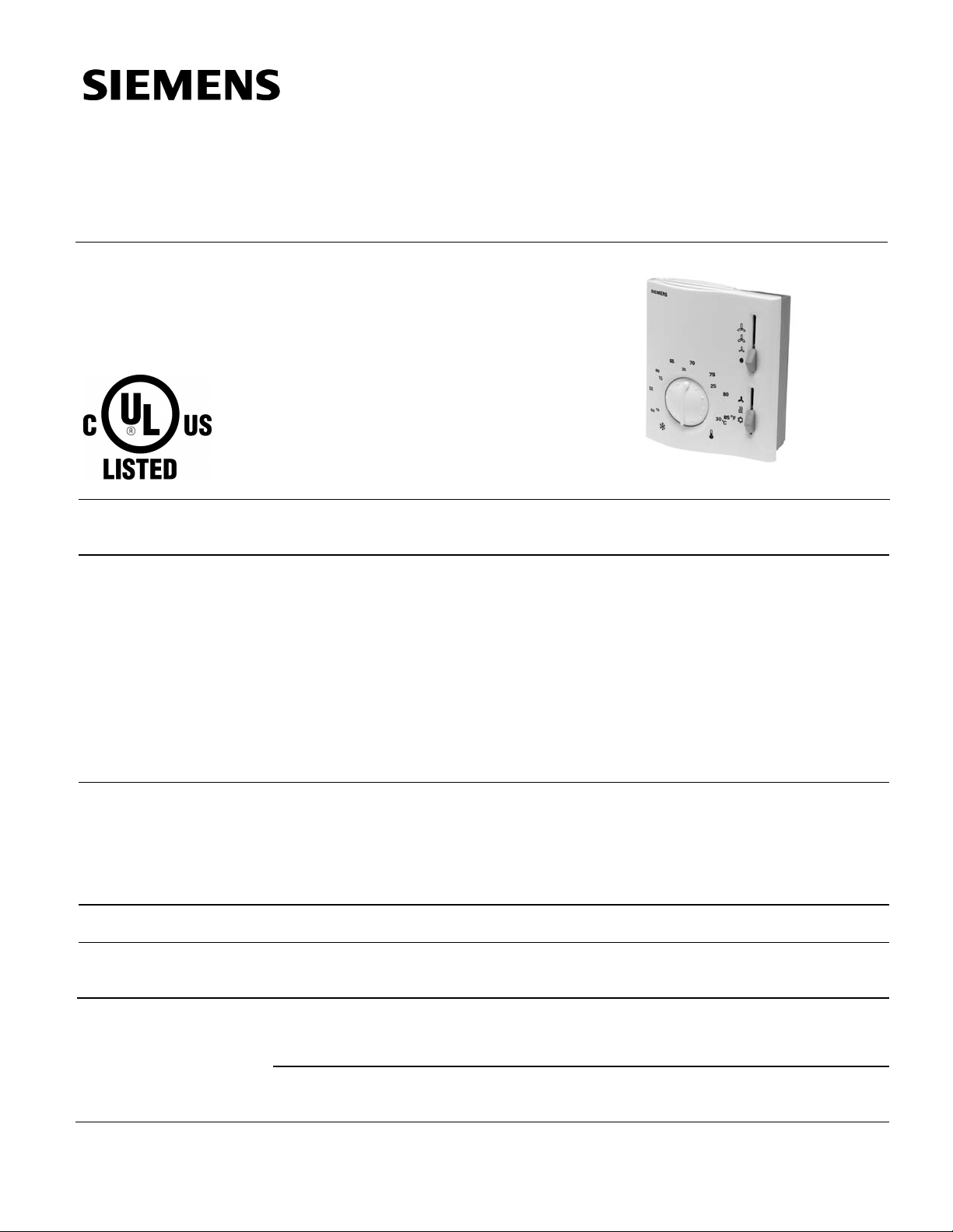
RAB10 Series
Technical Instructions
Two-pipe Fan Coil Room
Thermostat with Manual
Changeover
Document No. 155-524P25
ET RAB-1
March 2, 2007
Description
Features
Application
Product Numbers
Two-wire, gas diaphragm-based fan coil room thermostat with heating or cooling
sequence for two-pi pe fan coil app licat io ns .
• Manual, three-speed fan switch
• Dual setpoint tem peratur e sc ale
• Fan release function
• Two-point control algorithm (On/Off)
• 24 to 120 Vac, 277 Vac operating voltage
• Manual changeover switch
• Two mounting styles: electrical wall box or drywall
• Wall plate adapter (ARG70) included with electrical wall box mount styles
Typically used in commerc ial, high-ris e and light indus t r ial build in gs in conj uncti on w ith:
• Zone valves
• Thermal valves
• Fans
See Table 1.
Technical Design
The RAB10... fan coil room thermostat is based on a two-wire, gas diaphragm
technology.
Operation
Heating Mode
Cooling Mode
When the heating mode is manually selected, and the room temperature falls below the
selected setpoint, the heating contact is closed.
When the cooling mode is manually selected, and the room temperature rises over the
selected setpoint, the cooling contact is closed.
Siemens Industry, Inc.
Page 2
Technical Instructions RAB10 Series Two-pipe Fan Coil Room Thermostat
Document Number 155-524P25
March 2, 2007
Operation,
Continued
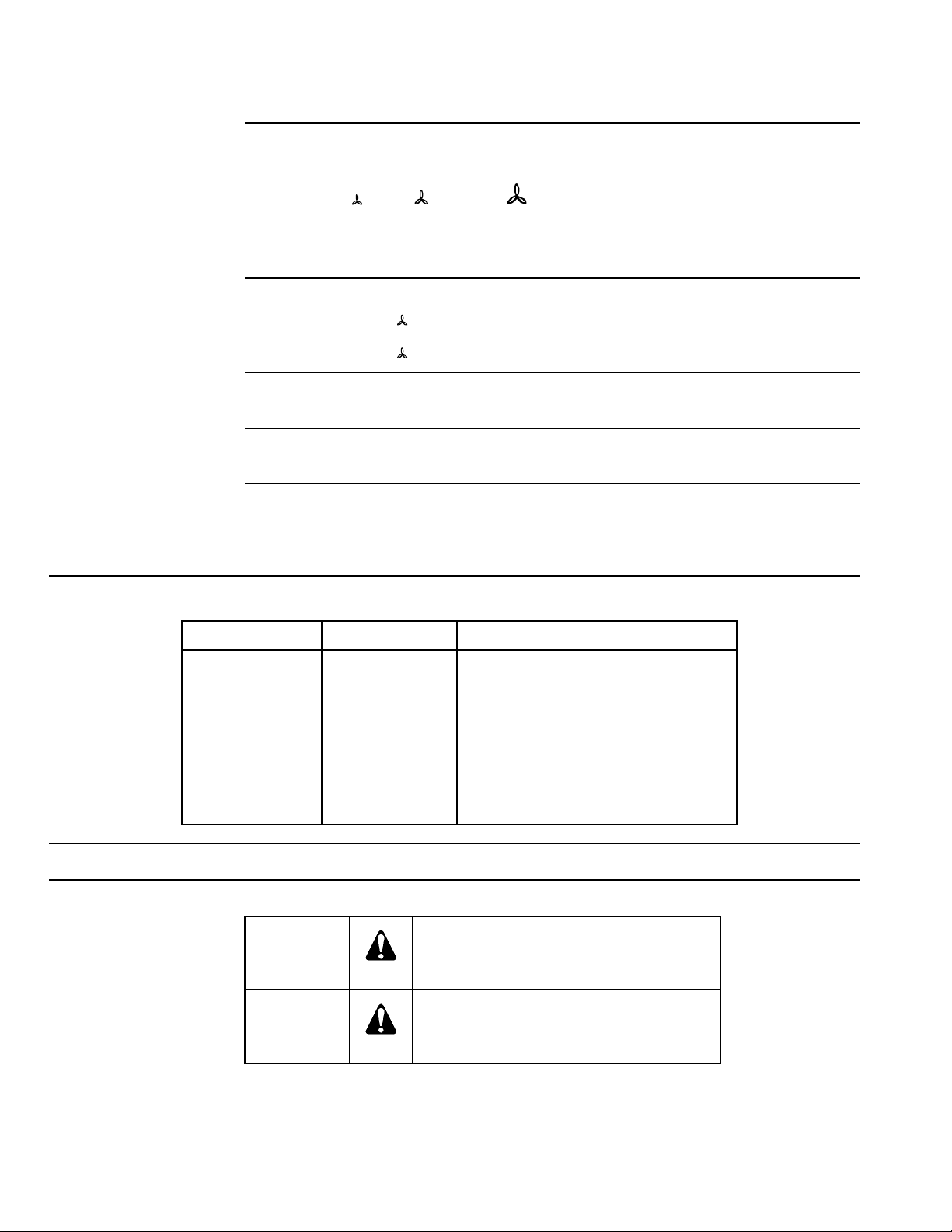
Fan Speed
Fan Release Setting
Ventilation
Changeover
Adjustments
The fan control speed can be controlled two ways:
• Manually, using the three-speed fan switch on the thermostat cover for continuous
operation.
• Automatically, by switching to the selected fan speed using the thermostat for
controlled operation. Prior to commissioning, the jumper position corresponding to
the thermostat function must be selected.
There are two jumper position choices on the printed circuit board:
− Jumper SR1
− Jumper SR2
When the ventilation function is selected (RAB10.1..), the heating and cooling contacts
are always open and the fan works at the selected speed.
The control algorithm can be selected with a switch located on the front of the controller
(change over switch).
The required temperature can be selected by a rotating setpoint adjuster at the front of
the thermostat.
High and low setpoint limit stops can be engaged to limit temperature range.
Mounting Style Product Number Description
(Low), (Medium), (High).
Selected fan speed as continuous operation
Auto Fan is switched at the same time as the valve
Table 1. Product Numbers.
Electrical Wall Box
(with wall box
adapter)
Drywall RAB10.1U 2-pipe; manual changeover; degrees
Accessory
ARG70 Wall Box Adapter
Warning/Caution Notations
WARNING:
CAUTION:
RAB10.1UW 2-pipe; manual changeover; degrees
Fahrenheit and Celsius; fan only
function
Fahrenheit and Celsius; fan only
function
Personal injury, or loss of life may occur if
you do not perform a procedure as
specified.
Equipment damage, or loss of data may
occur if you do not follow a procedure as
specified.
Page 2 Siemens Industry, Inc.
Page 3
RAB10 Series Two-pipe Fan Coil Room Thermostat Technical Instructions
Operation
Screw terminals for wires of 2 × 16 AWG or 1 × 14 AWG
Material Plastic
Conforms to CE requirements
Document Number 155-524P25
March 2, 2007
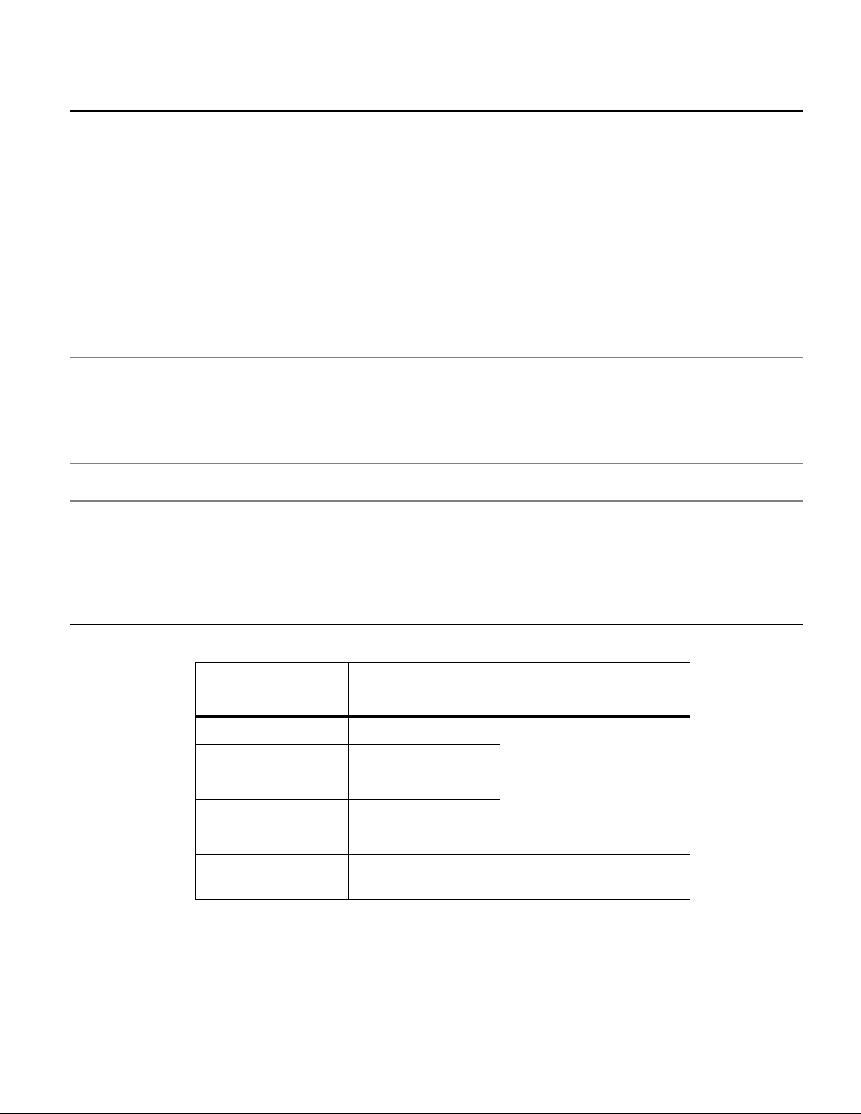
Specifications
Operating voltage 24 to 120 Vac, 277 Vac
Frequency 50/60 Hz
Setpoint adjustment range 50°F to 85°F (10°C to 30°C)
Setpoint limit stops Adjustable
Switching differential (SD) ≤1.8°F (1°C), fixed
Switch rating 6A RES, 3.5A FLA, 12A LRA
Switch action Single-Pole, Double-Throw (SPDT )
Selector switch Off/Low/Medium/High
Weight 5 oz. (0.14 kg)
Dimensions 3.80 × 4.45 × 1.68 inches
(96.4 × 113.1 × 42.8 mm)
Color Ivory white with gray selector knobs
Ambient Conditions
Wiring
Housing
Agency Certification
Temperature 32°F to 122°F (0°C to 50°C)
Relative humidity <95%
Transport/Storage
Temperature –4°F to 122°F (–20°C to 50°C)
Relative humidity <95%
Minimum 20 AWG
Enclosure rating NEMA1
Bellows Environmentally-friendly gas
UL listed to 893 (E35918)
cUL listed to Canadian standard
C22.2 No. 24-93
Table 2. Control Valves.
Part Number Description Technical
Instructions
SFA71U 24V NC
SFA11U 120V NC
155-521
SFA208V/25 208V NC
SFA277V/25 277V NC
FTA71 24V NC 155-109
599 Series Zone
Valves
Siemens Industry, Inc. Page 3
Two-way
Three-way
155-320P25
Page 4

Technical Instructions RAB10 Series Two-pipe Fan Coil Room Thermostat
Document Number 155-524P25
March 2, 2007
Mounting
• Locate the unit where the air temperature can be sensed as accurately as possible.
• Do not mount in direct sunlight or near other heat or refrigeration sources.
• Mounting height is approximately 60 inches (1.5 m) above the floor.
• The unit can be fitted to most commercially available recessed conduit boxes or
directly on the wall.
Figure 1. Recommended Mounting Locations.
(Dimensions in Inches)
WARNING:
1. This unit can be installed by authorized pers onn el on l y.
2. The unit must be de-energized and the operating voltage checked
before opening.
Setpoint Limit Stops
Adjustment
Installation
Required Tools
• An ARG70 wall plate adapter (provided with electrical wall box mount models) must
be used to mount to a 2 × 4-inch or 4 × 4-inch electrical wall box.
• An ARG70 wall plate adapter must be used to meet UL and cUL requirements.
• The thermostat must be mounted on a flat wall.
• All local electrical regulations must be complied with.
• If there are radiator valves in the room, set them to their fully open position.
To set limit stops, remove gray tabs located on the setpoint knob and position high and
low stops around the perimeter of knob as required. Each position on the setpoint dial is
1.8°F. See Figure 2.
• Small, flat-blade screwdriver
• 1/4-inch drill bit
• Drill motor
• Small mallet
• Pencil
Page 4 Siemens Industry, Inc.
Page 5

RAB10 Series Two-pipe Fan Coil Room Thermostat Technical Instructions
Document Number 155-524P25
March 2, 2007
Drywall Mounting
1. Loosen the two screws at the bottom of thermostat.
2. Lift the bottom of the thermostat cover from the thermostat base and push up to
remove cover.
3. Remove sub-base from back of thermostat.
4. Using the sub-base (packed with thermostat) as a template, mark the hole locations
with a pencil.
5. Drill two 1/4-inch diameter holes for plastic wall anchors (provided).
6. Using a mallet, tap in the plastic wall anchors flush wit h wa ll.
7. Pull the wiring through the opening in the upper portion of the sub-base.
8. Level mounting plate.
9. Using the two wood screws provided, fasten sub-base to wall. Thermostat is not
position sensitive.
10. Pull the wiring through the sub-base.
11. Position thermostat housing over the two mounting lugs located at the top of the
sub-base, and press down on cover until bottom lugs snap in place.
12. Terminate wires per wiring instructions on the inside of thermostat cover.
Optional: To set limit stops, remove gray tabs located on the setpoint knob and
position high and low stops around perimeter of knob as required.
Figure 2. Setpoint Limit Stops.
13. Place all thermostat switches in the “down” position to allow cover switch sliders to
fit over the switches.
14. Insert the top of the thermostat cover into the slots located on the top of the
thermostat and press down.
15. Tighten the two screws at the bottom of the thermostat.
16. Return selector switches to the normal position. Adjust setpoint dial to desired
setting.
The installation is now complete.
Siemens Industry, Inc. Page 5
Page 6

Technical Instructions RAB10 Series Two-pipe Fan Coil Room Thermostat
Document Number 155-524P25
March 2, 2007
4 × 4-inch Electrical Wall
Box Mounting
An ARG70 wall plate adapter is required to mount an RAB… thermostat to a 4 × 4-inch
electrical wall box. The ARG70 wall plat e ada pter is include d with elec tric a l wal l box
mount models.
1. Loosen the two screws at the bottom of thermostat.
2. Lift the bottom of the thermostat cover from the thermostat base and push up to
remove cover.
3. Using the four screws provided, fasten wall box adapter (3) to plaster ring (2),
supplied by others.
4. Pull wires through plaster ring (2).
5. Flex adapter mask (4) and snap in place inside wall box adapter (3).
6. Fasten sub-base (5), included with thermostat, to wall box adapter assembly (3)
and (4) with the two screws provided.
7. Follow Drywall Mounting Steps 7 through 16.
The installation is now complete.
Figure 3. 4 × 4-inch Electrical Wall Box Installation.
1 Electrical wall box
2 Plaster ring
5 Sub-base
6 Thermostat base
3 Wall box adapter *
7 Thermostat cover
4 Adapter mask *
* Included with ARG70
Page 6 Siemens Industry, Inc.
Page 7

RAB10 Series Two-pipe Fan Coil Room Thermostat Technical Instructions
Document Number 155-524P25
March 2, 2007
2 × 4-inch Electrical Wall
Box Mounting
An ARG70 wall plate adapter is required to mount an RAB… thermostat to a 2 × 4-inch
electrical wall box. The ARG70 wall plate ada pter is inc lude d with electr ica l wal l box
mount models.
1. Loosen the two screws at the bottom of thermostat.
2. Lift the bottom of the thermostat cover from the thermostat base and push up to
remove cover.
3. Using the two screws provided, fasten wall box adapter (3) to plaster ring (2),
supplied by others.
4. Pull wires through plaster ring (2).
5. Flex adapter mask (4) and snap in place inside wall box adapter (3).
6. Fasten sub-base (5), included with thermostat, to wall box adapter assembly (3)
and (4) with the two screws provided.
7. Follow Drywall Mounting Steps 7 through 16.
The installation is now complete.
Figure 4. 2 × 4-inch Electrical Wall Box Installation.
1 Electrical wall box
5 Sub-base
3 Wall box adapter *
4 Adapter mask *
6 Thermostat base
7 Thermostat cover
* Included with ARG70
Siemens Industry, Inc. Page 7
Page 8

Technical Instructions RAB10 Series Two-pipe Fan Coil Room Thermostat
W/Y Control output actuator
cooling
Document Number 155-524P25
March 2, 2007
Maintenance
Diagrams
The room thermostat is completely maintenance-free. If inoperable, replace entire unit.
WARNING:
High voltage. Disconnect power before servicing. Metal part is not
grounded.
L Operating voltage
M1 3-speed fan
N Neutral
N1 Room thermostat
G1 Control output fan speed I
(Low)
G2 Control output fan speed II
(Medium)
G3 Control output fan speed III
(High)
ZV Zone valve or thermal valve
Figure 5. Wiring.
T Room temperature
SD Switching differential
SP Room temperature
setpoint
W Valve output signal
heating
Y Valve output signal
Page 8 Siemens Industry, Inc.
Heating Mode Cooling Mode
Figure 6. Operating.
Page 9

RAB10 Series Two-pipe Fan Coil Room Thermostat Technical Instructions
Siemens Indus try, Inc.
+ 1 847-215-1000
Your feedback is important to us. If you have
Document No. 155-524P25
Figure 9. ARG70.
Document Number 155-524P25
March 2, 2007
Dimensions
Dimensions in inches
(millimeters)
Figure 7. RAB10… Unit.
Figure 8. Base Plate.
Information in this publication is based on current specifications. The company reserves the right to make changes in specifications and models as
design improvements are introduced. Product or company names mentioned herein may be the trademarks of their respective owners.
© 2007 Siemens Industry, Inc.
Building Technologies Division
1000 Deerfield Parkway
Buffalo Grove, IL 60089
comments about this document, please send them
to SBT_technical.editor.us.sbt@siemens.com
Printed in the USA
Page 9
 Loading...