

Page 1
Siemens Building Technologies G3210xx 2017-11-01 1/4
G3210
de
Installationsanleitung
es
Instrucciones de montaje
el
Οδηγίες Εγκτατάστασης
en
Installation Instructions
pt
Instruções de montagem
sk
Návod na montáž
fr
Instructions d’installation
sv
Installationsanvisning
cs
Montážní list
it
Istruzioni di montaggio
fi
Asennusohje
pl
Instrukcja montażu
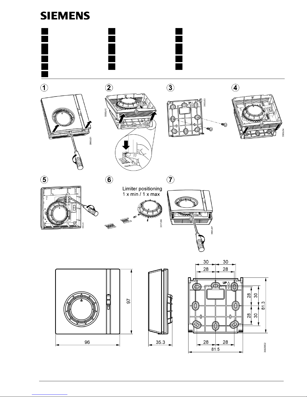
RAA...
nl
Installatie-aanwijzing
da
Installationsvejledning
hu
Telepítési leírás
zh
安装说明书
Dimensions in mm
Page 2
Siemens Building Technologies G3210xx 2017-11-01 2/4
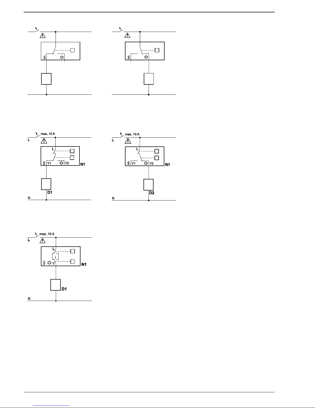
RAA11 / RAA21
T
L
N
L
Y1 Y2
N1
D1
32101A01
max. 10 A
RAA11 / RAA21 - Heating mode
T
3210A02
D2
N1
L
N
L
Y1 Y2
max. 10 A
RAA11 / RAA21 - Cooling mode
D1 Zone valve or thermal valve for heating
D2 Zone valve or thermal valve for cooling
L Switching voltage
AC 24…250V
N1 Room thermostat
Y1 Control output
“Heating”, AC 24...250V
Y2 Control output
“Cooling”, AC 24...250V
N Neutral
T Thermostat element
(gas-filled diaphragm)
RAA31
T
3210A03
S
RAA31 - Heating mode
T
3210A04
S
RAA31 - Cooling mode
D1 Zone valve or thermal valve for heating
D2 Zone valve or thermal valve for cooling
L Switching voltage
AC 24…250V
N1 Room thermostat
S ON/OFF switch
Y1 Control output
“Heating”, AC 24...250V
Y2 Control output
“Cooling”, AC 24...250V
N Neutral
T Thermostat element
(gas-filled diaphragm)
RAA41
S
32104A05
T
/
D1 Zone valve or thermal valve for heating
L Switching voltage
AC 24…250V
N1 Room thermostat
S Selector for Heating / OFF / Cooling
Y Control output
“Heating”, AC 24...250V
T Thermostat element
(gas-filled diaphragm)
Page 3

Siemens Building Technologies G3210xx 2017-11-01 3/4
de
es
Das Gerät gilt für die Entsorgung als Elektronik-Altgerät im
Sinne der Europäischen Richtlinie 2012/19/EU und darf nicht
als Haushaltmüll entsorgt werden.
Entsorgen Sie das Gerät über die dazu
vorgesehenen Kanäle.
Beachten Sie die örtliche und aktuell gültige
Gesetzgebung.
Este aparato es válido para su eliminación como residuo de
aparato electrónico conforme a la Di-rectiva europea
2012/19/UE y no se debe des-echar como basura
doméstica.
Deseche el aparato a través de los canales previs-
tos para tal fin.
Tenga en cuenta la legislación local y vigente ac-
tualmente.
el
en
Η συσκευή ως προς την απόρριψή της έχει ταξινομηθεί ως
απόβλητο ηλεκτρονικού εξοπλισμού σύμφωνα με την
Ευρωπαϊκή Οδηγία 2012/19/ΕΕ και δεν επιτρέπεται να
απορρίπτεται μαζί με τα οικιακά απορρίμματα.
Απορρίπτετε τη συσκευή μέσω των δικτύων που
έχουν οριστεί.
Τηρείτε την τοπική ισχύουσα νομοθεσία.
The device is considered an electronics device for disposal
in terms of European Directive 2012/19/EU and may not be
disposed of as domestic garbage.
Dispose of the device through channels provided
for this purpose.
Comply with all local and currently applicable laws
and regulations.
pt sk
Para a eliminação, o aparelho é considerado como resíduo
de equipamento eletrónico nos termos da Diretiva Europeia
2012/19/UE e não deve ser eliminado como lixo doméstico.
Elimine o aparelho através dos canais previstos
para o efeito.
Respeite a legislação local e atualmente em vigor.
V zmysle Európskej smernice 2012/19/EÚ sa tento prístroj
považuje za odpad z elektronických zariadení a nesmie sa
zlikvidovať ako odpad z domácnosti.
Prístroj zlikvidujte predpísaným spôsobom.
Dodržiavajte miestne a aktuálne platné zákonné
predpisy.
fr sv
L’appareil est considéré comme un appareil élec-tronique
usagé destiné à être éliminé au sens de la Directive
européenne 2012/19/UE et il ne doit pas être jeté comme un
déchet ménager.
Jetez l’appareil par les voies prévues à cet effet.
Veuillez respecter la législation locale actuellement
en vigueur.
Vid avfallshantering betraktas enheten som elektrisk eller
elektronisk produkt i enlighet med EU-direktivet 2012/19/EU
och får inte slängas som hushållsavfall.
Avfallshantera enheten på det sätt som föreskrivs.
Följ den lokala och aktuella lagen.
cs it
Přístroj se při likvidací považuje za odpadní elektrické a
elektronické zařízení ve smyslu Evropské směrnice
2012/19/EU a nesmí se likvidovat jako domovní odpad.
Likvidujte přístroj prostřednictvím k tomu určených
kanálů.
Dodržujte místní a aktuálně platnou legislativu.
L'apparecchio è considerato, ai fini dello smalti-mento, come
rifiuto di apparecchiatura elettronica ai sensi della Direttiva
Europea 2012/19/UE e non deve essere smaltito insieme ai
rifiuti domestici.
Smaltire l'apparecchio tramite gli appositi canali.
Rispettare le normative locali attualmente in
vigore.
fi pl
Laite hävitetään elektroniikkaromuna EU-direktiivin
2012/19/EU mukaisesti eikä sitä saa hävittää
kotitalousjätteen mukana.
Hävitä laite tarkoituksenmukaisen kierrätyspisteen
kautta.
Noudata paikallista ja voimassaolevaa
lainsäädäntöä.
Zużyty sprzęt elektroniczny podlega obowiązkowi utylizacji w
rozumieniu dyrektywy europejskiej 2012/19/UE i nie może
być utylizowany razem z odpadami gospodarstwa
domowego.
Urządzenie należy oddać do utylizacji w
specjalistycznej firmie.
Należy przy tym przestrzegać lokalnych i aktualnie
obowiązujących przepisów.
Page 4

Siemens Building Technologies G3210xx 2017-11-01 4/4
Issued by
Siemens Switzerland Ltd.
Building Technologies Division
International Headquarters
Gubelstrasse 22
CH-6300 Zug
Tel. +41 41-724 24 24
© Siemens Switzerland Ltd, 2017
Technical specifications and availability subject to change without notice.
www.siemens.com/buildingtechnologies
nl da
Het toestel geldt voor de afvalverwerking als af-gedankte
elektronische apparatuur conform de Europese richtlijn
2012/19/EU en mag niet via het huishoudelijke afval worden
afgevoerd.
Verwijder het toestel via de daartoe bestemde ka-
nalen.
Let op de lokale en momenteel geldende voor-
schriften.
I henhold til det europæiske direktiv 2012/19/EU anses
udstyret for at være brugt elektronisk udstyr og må ikke
bortskaffes som husholdningsaffald.
Bortskaf udstyret ved anvendelse af de godkendte
metoder.
Overhold den nationale og aktuelt gældende
lovgivning.
hu zh
A berendezés ártalmatlanítás szempontjából az Európai
Parlament és a Tanács 2012/19. irányelve értelmében
elektronikus berendezésnek számít, és nem
ártalmatlanítható kommunális hulladékként.
A berendezést megfelelő módon ártalmatlanítsa.
Vegye figyelembe a hatályos helyi jogszabályokat.
该设备是需要根据欧洲指令2012/19/EU进行处置的电子设备,
不得作为生活垃圾处理。
通过为此目的提供的渠道处置该设备。
请遵守当地现行的所有法律法规。
 Loading...