

Page 1
Installation Instructions
RAA Series Room Thermostats
Product Numbers
RAA10C
RAA10CW
RAA20U
RAA20UW
Required Tools
• Flat-blade screwdriver
• Wire strippers
• Level
• Electric drill
Expected Installation Time
30 minutes
Installation
Document No. 129-521
March 7, 2007
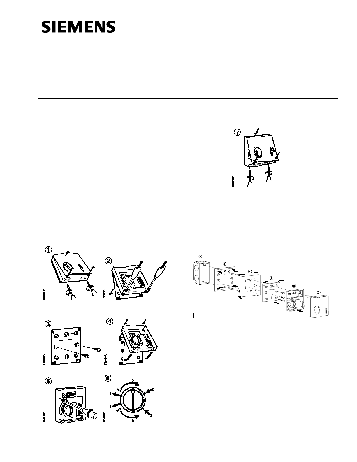
ARG70 Wall Plate Adapter
NOTE: An ARG70 Wall Plate Adapter is required to
mount an RAA… Thermostat to a 2 × 4
electrical wall box to meet UL and cUL
requirements.
Item Number 129-521, Rev. AA Page 1 of 2
Figure 1. 2 × 4-inch Electrical Wall Plate Installation.
1 Electrical wall box 5 Sub-base
3 Wall plate adapter * 6 Thermostat base
4 Adapter mask * 7 Thermostat cover
* Included with ARG70
The installation is now complete.
Page 2
Document No. 129-521
Siemens Indus try, Inc.
+ 1 847-215-1000
Your feedback is important to us. If you have
Document No. 129-521
Installation Instructions
March 7, 2007
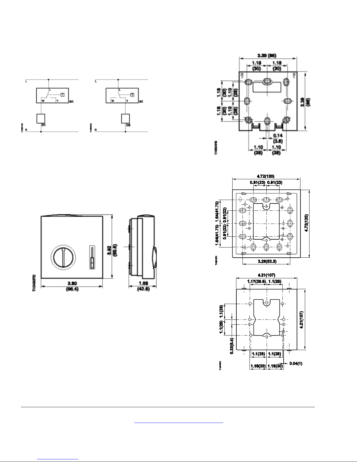
Wiring Diagrams
RAA10… and RAA20…
Heating Mode Cooling Mode
D1 Heating device N1 Room thermostat
D2 Cooling device T Thermal switch
L Operating voltage W Heating control output
N Neutral Y Cooling control output
Figure 2. Wiring Diagrams.
Dimensions
Figure 3. Dimensions in Inches (Millimeters).
Figure 4. Base Plate Dimensions in Inches (Millimeters).
Information in this publication is based on current specifications. The company reserves the right to make changes in specifications and models as
design improvements are introduced. Products or company names mentioned herein may be the trademarks of their respective owners. © 2007
Siemens Industry, Inc.
Building Technologies Division
1000 Deerfield Parkway
Buffalo Grove, IL 60089
comments about this document, please send them
to SBT_technical.editor.us.sbt@siemens.com
Figure 5 ARG70.
Printed in the USA
Page 2 of 2
 Loading...