

Page 1
CE1N3002en
25.02.2008
Building Technologies
3
002
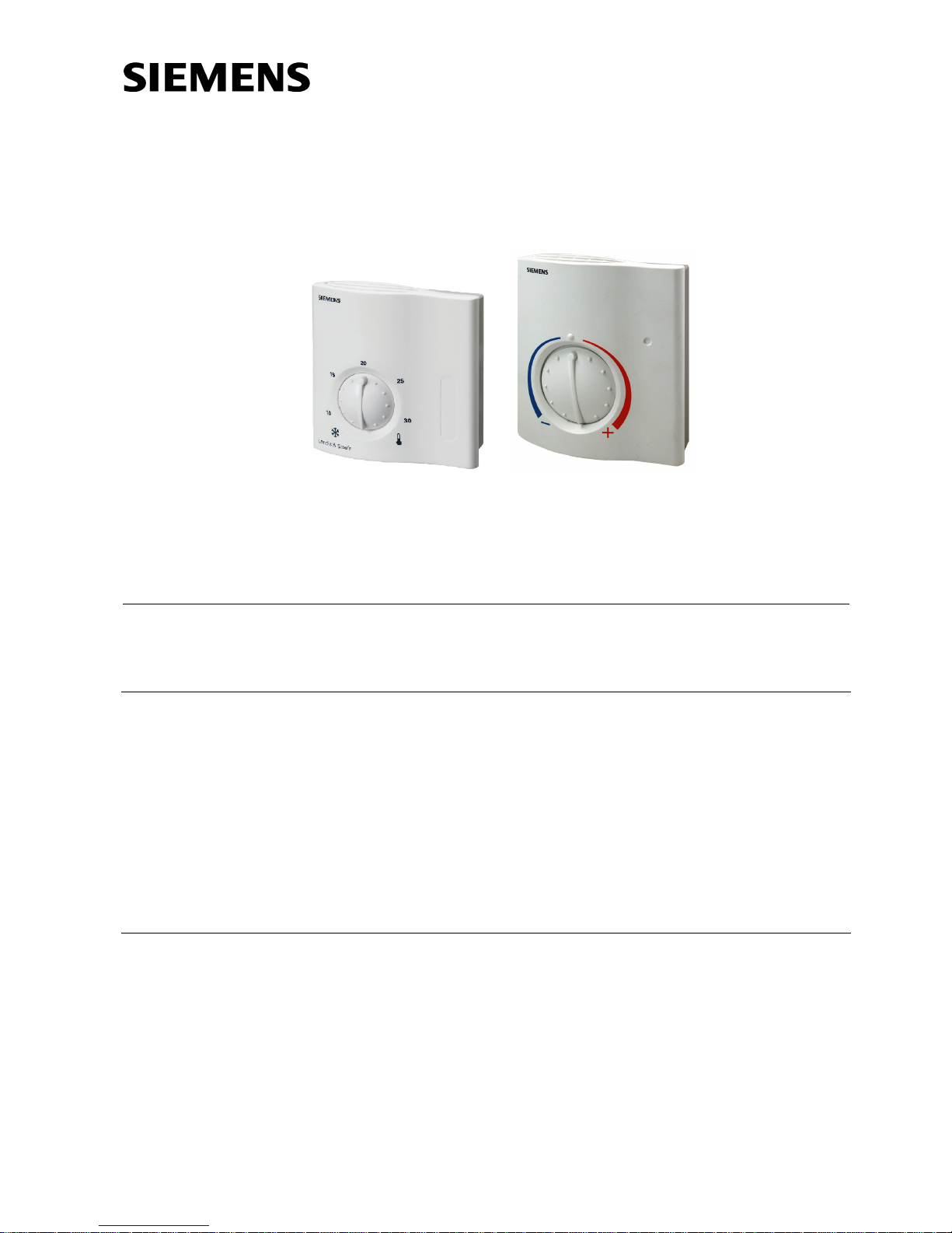
RAA20 RAA200
Room thermostats RAA20..
Adjustable for heating only or cooling only
• 2-position control
• Switching voltage AC 24…250 V
Use
The RAA20.. room thermostat is used in heating only or cooling only systems to maintain the selected room temperature.
Typical use:
• Residential buildings
• Light industrial buildings
In conjunction with
• zone valves or thermal valves
• gas or oil burners
• fans
• pumps
Functions
The RAA20.. room thermostat has separate outputs for heating only and cooling only.
If the room temperature falls below the selected setpoint, the heating contact will close.
If the room temperature exceeds the selected setpoint, the cooling contact will close.
Page 2
2/4
Siemens Room Thermostat RAA20 CE1N3002en
Building Technologies 25.02.2008
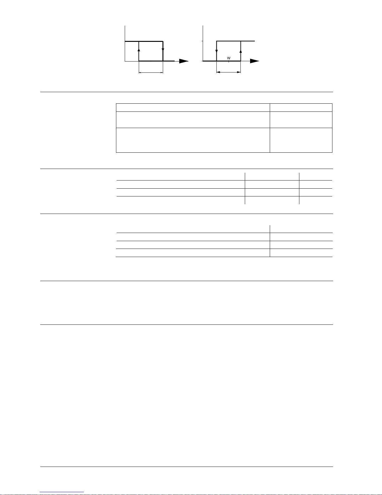
Y
T[°C]
ON
OFF
W
SD
3010D01
Y
T[°C]
ON
OFF
SD
3010D02
T Room temperature
SD Switching differential
w Room temperature
setpoint
Y1 Output signal "Heating"
Y2 Output signal "Cooling"
Type summary
Functionality Product no. (ASN)
Room thermostat for heating or cooling mode
Switching voltage AC 24...250 V
RAA20
Room thermostat for heating or cooling mode with large dial
(large temperature setting knob) and color scale
Switching voltage AC 24...250 V
RAA200
Equipment combinations
Description Product no. (ASN) Data sheet
Motoric on / off actuator
SFA21...
4863
Thermal actuator (for radiator valves)
STA21...
4893
Thermal actuator (for small valves 2.5 mm)
STP21...
4878
Accessories
Description Product no. (ASN)
Adapter plate 120 x 120 mm for 4 x 4“ conduit boxes ARG70
Adapter plate 96 x 120 mm for 2 x 4“ conduit boxes ARG70.1
Adapter plate for surface wiring 112 x 130 mm ARG70.2
Technical design
Key features of the RAA20.. room thermostat:
• 2-position control
• Gas-filled diaphragm
Adjustments
The required temperature setpoint is selected with the setting knob on the front of the
thermostat.
The setpoint setting range can be mechanically limited by means of setpoint limiters
under the unit cover.
Function diagrams
.
.
.
.
.
.
.
.
.
Page 3

3/4
Siemens Room Thermostat RAA20 CE1N3002en
Building Technologies 25.02.2008
Notes
The thermostat should be located where the room temperature can be acquired as
accurately as possible, without getting adversely affected by direct solar radiation or
other heat or refrigeration sources.
Mounting height is about 1.5 m above the floor.
The thermostat can be fitted to most commercially available recessed conduit boxes or
directly on the wall.
Only authorized personnel may open the unit to perform service
(Caution: AC 24…250 V!). The unit must be isolated from the mains supply before
opening.
When installing the unit, fix the baseplate first, then hook on the thermostat body and
make the electrical connections. Then, fit the cover and secure it (also refer to separate
mounting instructions).
The thermostat must be mounted on a flat wall.
The local electrical regulations must be complied with.
If there are thermostatic radiator valves in the reference room, set them to their fully
open position.
The room thermostat is maintenance-free.
The diaphragm is filled with environment-friendly gas.
The housing is made of plastic.
Technical data
Switching capacity
Voltage
Current
Frequency
AC 24...250 V
0.2…6(2) A
50 or 60 Hz
Switching differential SD ≤1 K
Setpoint setting range 8…30 °C
Operation
Climatic conditions
Temperature
Humidity
Pollution degree
To IEC 721-3-3
Class 3K5
0…50 °C
<95% r.h.
Normal, to EN 60730
Transport / storage
Climatic conditions
Temperature
Humidity
Mechanical conditions
To IEC 721-3-2
Class 2K3 / 1K3
-20…50 °C
<95% r.h.
Class 2M2
conformity
EC directive on EMC
Low-voltage directive (LVD)
2004/108/EC
2006/95/EC
Product standards
Automatic electrical controls for
household and similar use
EN 60730-1 and
EN 60730-2-9
Mounting, installation
and commissioning
Maintenance
Mechanical design
Operational data
Environmental conditions
Norms and standards
Page 4

4/4
Siemens Room Thermostat RAA20 CE1N3002en
Building Technologies 25.02.2008
EMC – standard
Emission
EN 61000-3-2 and
EN 61000-3-3
C-Tick conformity to
EMC emission standard
AS/NSZ 4251.1:1994
Safety standard
Degree of protection of housing
II to EN 60730
IP30 to EN 60529
Screw terminals for
2 x 1.5 mm2 or 1 x 2.5 mm2 (min. 0.5 mm2 )
Weight 0.14 kg (RAA20)
0.20 kg (RAA200)
Color White, NCS S 0502-G (RAL 9003)
Connection diagrams
N
L
D1
N1
Y1 Y2
L
T
3001A01
N
L
N1
Y1 Y2
L
D2
T
3001A02
D1 Zone valve or thermal
valve for heating
D2 Zone valve or thermal
valve for cooling
L Switching voltage
AC 24…250 V
N1 Room thermostat
Y1 Control output "Heat-
ing", AC 24…250 V
Y2 Control output "Cool-
ing", AC 24…250 V
N Neutral conductor
T Thermostat element
(gas-filled diaphragm)
Dimensions
96,4
99,6
42,8
3002M01
3001M02
30 30
28
3,6
28
86
86
2828
30
30
Room thermostat /
baseplate
RAA20
RAA200
©2003 – 2008 Siemens Switzerland Ltd. Subject to change
 Loading...