

Page 1

PAGE 1
RAA02... INSTALLATION DIAGRAMS
RAA02... Installation Diagrams
• The room temperature controller should be fitted in
the main living room.
• The place of installation should be chosen so that
the sensor can capture the room temperature as
accurately as possible, without being affected by
direct solar radiation or other heating or cooling
sources.
• Mounting height is approx. 1.5m above the floor.
• The unit can be fitted to most commercially available
recessed conduit boxes or directly on the wall.
• For the electrical installation, the local safety
regulations and standards must be complied with.
• If the reference room is equipped with thermostatic
radiator valves, they must be set to their fully open
position.
Step 4.Step 2.
Step 5.
Step 1.
Step 3.
An optional sub-base is available on request, to
assemble unit just follow these five simple steps and
the information on the following page.
If you have any difficulty or require further
information, please contact our helpline telephone:
01527 406224
F
B
24°C
11°C
C
s
HVAC PRODUCTS
Page 2
PAGE 2
RAA02... INSTALLATION
s
Fix the sub-base using two of the available
holes marked ’F’.
Step 1.
Remove the cover by releasing clip ‘C’ with a
screwdriver.
Step 2.
The unit can now be fixed to either the subbase or the wall by means of two screws
maximum diameter 3.5mm using the holes
marked ‘B ’ provided in the base.
Step 3.
NB: The thermostat is for use with fixed wiring
only.
You can limit the temperature range or lock the
set limit by means of tappets as shown.
Step 4.
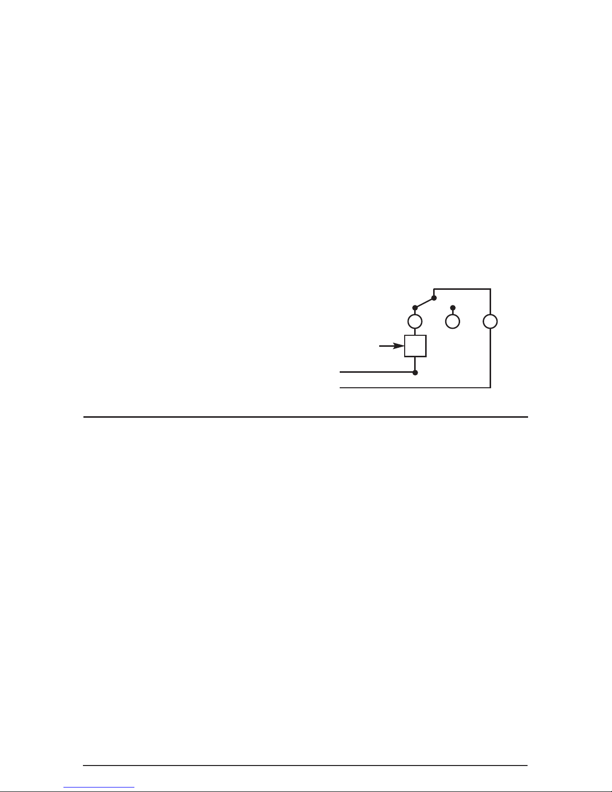
ELECTRICAL CONNECTIONS
Thread the cables through the slot in the base,
make the connections to the terminals as
shown on the diagram inside the cover and
illustrated on the right.
TECHNICAL DATA
Contacts rating: 16 (6) A/250V
Temperature range: 5 - 30°C
Differential: 0.8°C
Protection class: I
Degree of protection: IP30
Number of automatic cycles: II (100,000)
Temperature rate of change: 1K/15min.
Switch action: 2B
Dirt resistance: normal ambient
Note: Remote switch with class <A>
disconnection, i.e. 3mm. contact gap in each
pole must be provided. Nominal cross sectional
area: min. 1.5mm
2
Max. 2.5mm2.
NOTES
U
2
3 1
Load
Pump
Valve
etc.
No neutral required
Must be earthed
N
L
+
-
 Loading...