

Siemens QVM62.1 Installation Instructions Manual
Installation Instructions
QVM62.1 Air Velocity Sensor
Personal injury/loss of life may
procedures as specified.
Equipment damage or loss of
specified.
Product Description
This sensor is used to measure the air ve loc ity in a
duct and provide a 0 to 10V signal to a controller
that is proportional to the velocity. This allows the
controller to maintain a constant airflow in the duct,
balance out pressure fluctuations (supply or exhaust
air control), or just monitor the flow in a duct. The Air
Velocity Sensor is generally used for modulating fan
control in primary applications to set the basic
volume flow.
Product Number
QVM62.1
Warning/Caution Notations
WARNING:
CAUTION:
occur if you do not follow the
data may occur if you do not
follow the procedures as
Document No. 129-095
September 24, 2009
Installation
Probe Mounting Flange and Sensor
1. Determine the depth of insertion required for
the probe and assemble the extension tube
and/or probe end cap onto the primary sensor
head tube.
NOTE: If the insertion depth required is less
than or equal to 5.7 inches (145 mm)
the extension tube may be removed by
disconnecting the probe cable at the
transducer head, and sliding the
extension tube off the cable. (With the
extension tube installed, the probe’s
depth of insertion is 11.8 inches
[300mm].) If the extension tube is
removed, be sure to reinstall the
probe’s end cap on the cable before
rewiring it to the transducer head.
2. Position the probe mounting flange on the duct
where will be installed. Lightly tap the screw
heads to create drill marks for the mounting
screw holes.
Required Tools
• Pencil
• Hammer
• Center hole punch
• Screwdrivers
• Four - #8 × 1/2-inch sheet metal screws
• Electric drill with 1/8-inch and 7/8-inch
drill bits
Expected Installation Time
45 minutes
Prerequisites
Field wiring must be pulled to installation location.
Item Number 129-095, Rev. AA Page 1 of 3
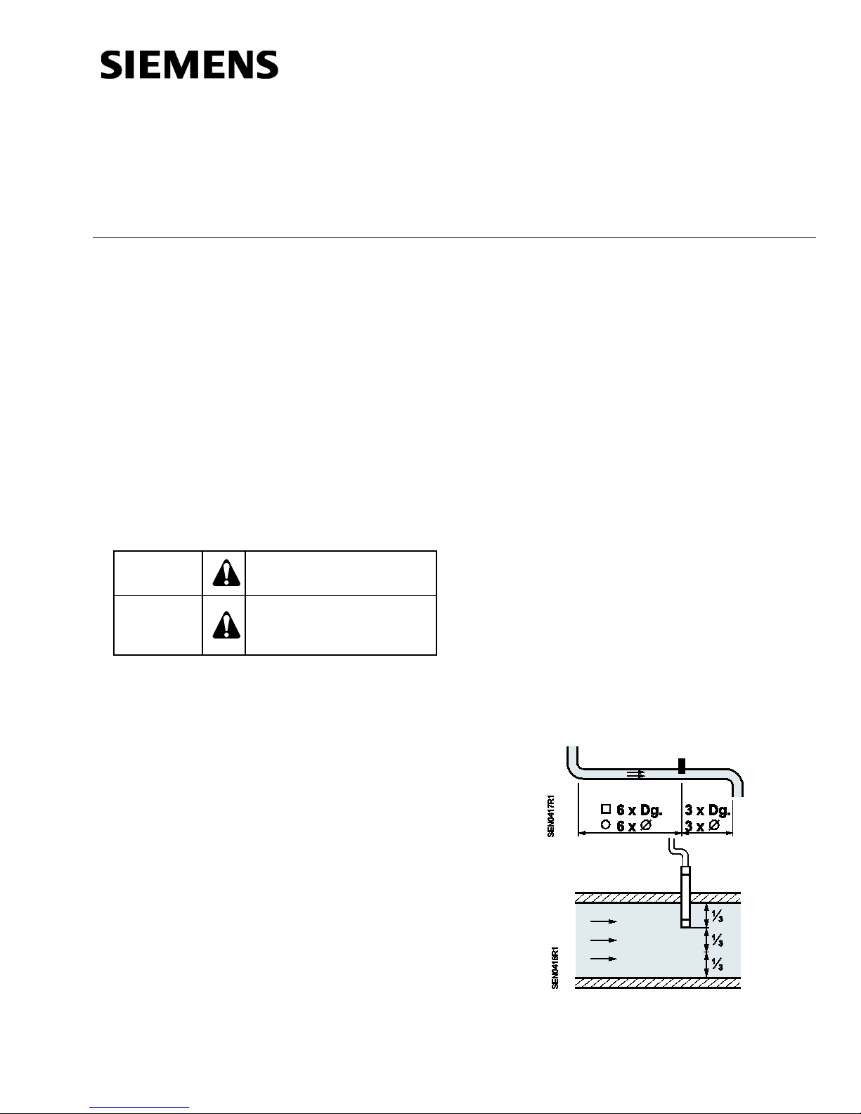
NOTE: Install the sensor in the ductwork in a
location where the airflow is not
turbulent. Do not place it close to
dampers, registers, or bends in
ductwork.
Figure 1. Mounting Locations.
Document No. 129-095
CAUTION:
can irreparably damage the unit.
.
Installation Instructions
September 24, 2009
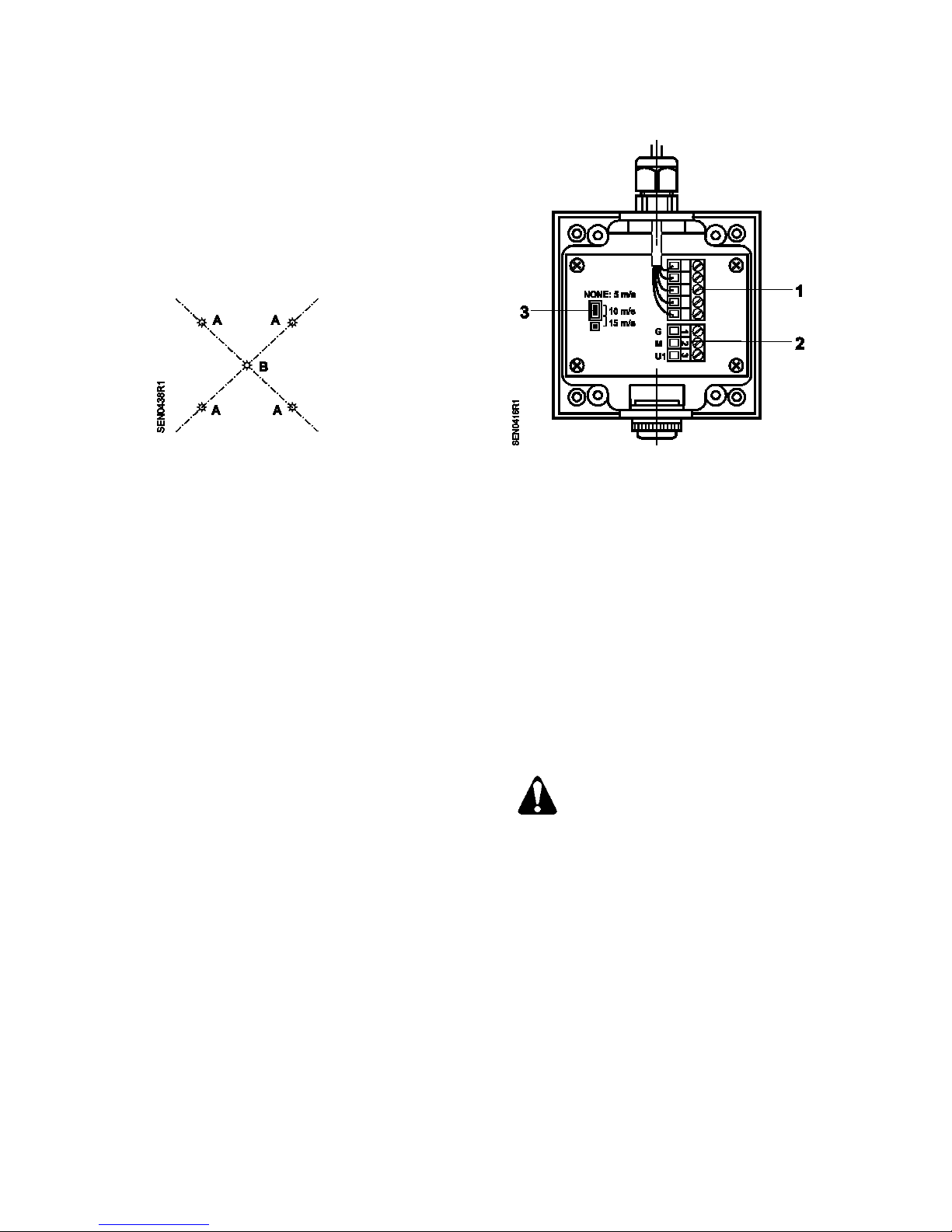
3. Draw a line between opposite drill marks,
farthest from each other, and make a drill mark
with the punch, at the intersection of the two
lines.
4. Drill four 1/8-inch holes for the mounting screws
at the points labeled “A”, and a 7/8-inch
diameter hole at the point labeled “B” (see
Figure 2).
Figure 2. Mounting Screw Locations.
5. Secure the flange to the duct using the screws
included with the flange and insert the probe into
the duct. Do not tighten the mounting screw at
this time.
Transducer
1. Remove the cover from the transducer head
unit.
2. Hold the base on the duct or structure to which it
is to be mounted and mark the center positions
of the four mounting holes.
NOTE: Make sure there is enough slack in the
probe’s cable so that, if necessary, the
probe can be removed for servicing or
replacement.
3. Make drill hole marks with the punch at the
mounting hole points, and drill four 1/8-inch
holes.
4. Secure the transducer head to its mounting
location with four #8 × 1/2-inch sheet metal
screws.
5. Set jumper for desired airflow range (see
Figure 3).
6. Connect the Field wiring to the transducer head
connector (see Figure 3.)
1 Terminal block for connection to the
immersion stem
2 Terminal block for connection to controller
3 Plug-in unit for setting the three velocity
ranges. The following applies:
No plug-in jumper = 0 to 5 m/s
Plug-in jumper on 1 and 2 = 0 to 10 m/s
(factory setting)
Plug-in jumper on 2 and 3 = 0 to 15 m/s
Figure 3. Wiring and Setting Elements.
.
7. Reinstall the cover
The sensor head connections are not
protected against 24 Vac operating
voltage.
If the unit power supply lead being
connected to terminal G is live during
the installation of the sensor, contact
with any of the sensor head terminals
8. Set the probe’s depth of insertion and position
the arrow on the probe cap so that it points in
the direction of the airflow.
9. Tighten the mounting screw located on the side
of the mounting flange (see Figure 4).
Page 2 of 3 Siemens Industry, Inc.
The installation is now complete.
 Loading...