

Siemens QVE1901U Technical Instructions
QVE1901U
Flow Switch
Description
Technical Instructions
Document No. 155-711
September 20, 2012
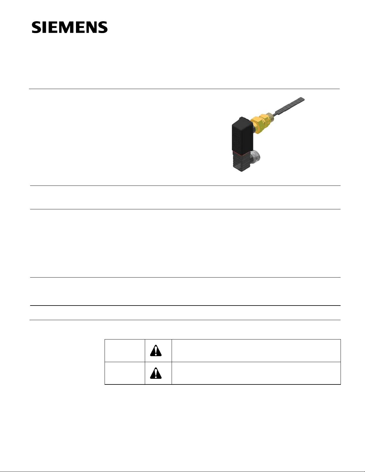
Flow switch for liquids in piping 3/4-inch to 8-inch (20 mm to 200 mm) diameter
Features
Application
Product Number
• Contact load/switching capacity:
Maximum 24 Vac, 1 A, 26 VA
Maximum 24 Vdc, 1 A, 20 W
• Nominal pressure maximum 365 psi
• Manual setting of contact type (NO/NC)
• Housing IP 65 (excluding conduit adapter)
• Maintenance-free
The QVE1901U Flow Switch is used in HVAC installations to monitor the flow of fluids
in hydraulic systems, especially in refrigeration, heat pump and heating installations (for
example: for use with condensers, boilers, heat exchangers, and so on).
QVE1901U
Warning/Caution Notations
WARNING:
CAUTION:
Personal injury/loss of life may occur if you do not perform a
procedure as specified.
Equipment damage may occur if you do not perform a
procedure as specified.
Siemens Industry, Inc.
Technical Instructions QVE1901U Flow Switch
Document Number 155-711
September 20, 2012
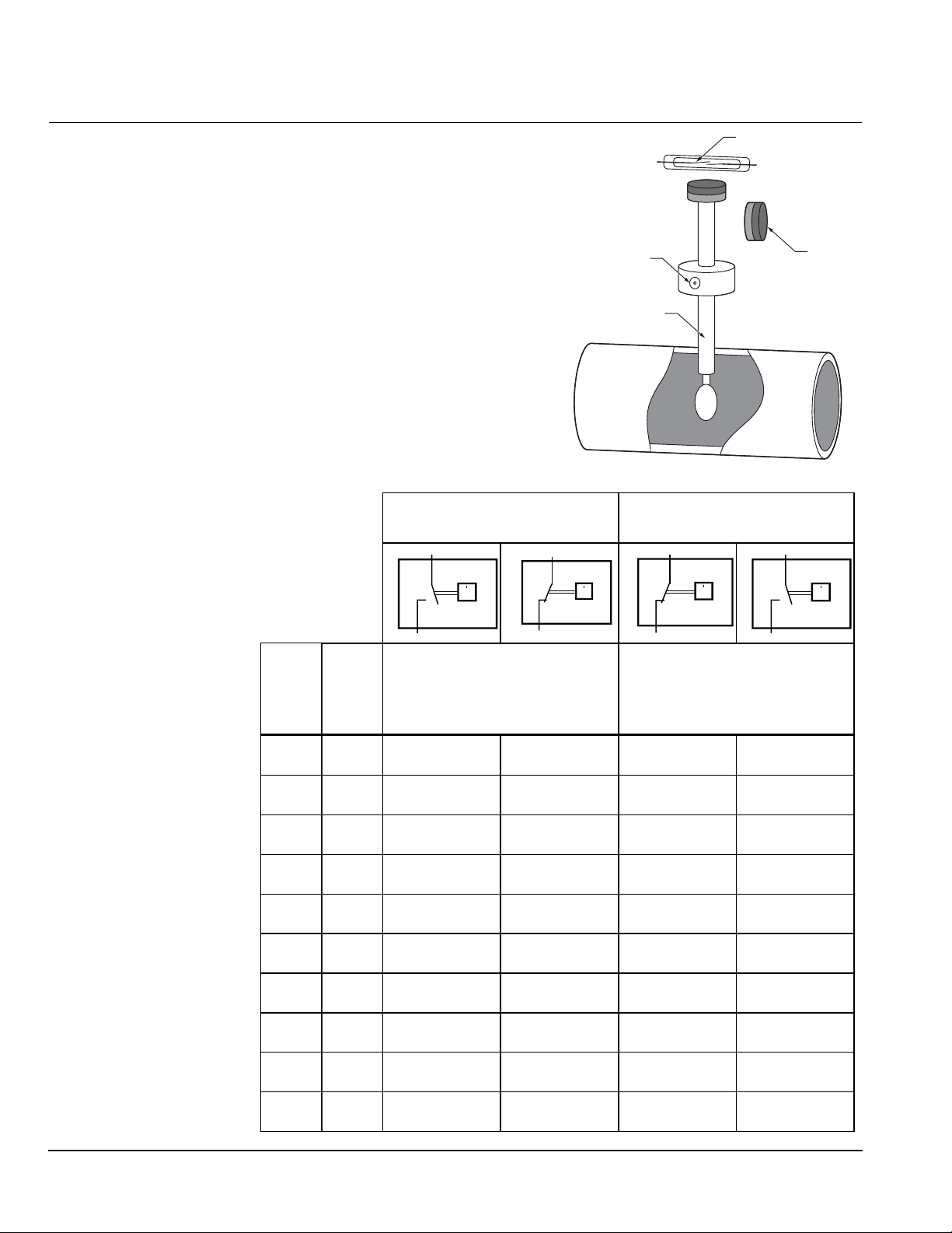
Mechanical Design
The device records the flow of monitored
Reed Contact (3)
medium via a paddle system (1), which
has a permanent magnet (2) attached at its
upper end. A reed contact (3) is positioned
outside the flow above this magnet. A
Magnet (2)
N
S
N
S
second magnet (4) with opposite polarity is
used to create a reset force. The paddle
system moves once it comes into contact
Shaft
Magnet (4)
with the monitored flow. The magnet (2)
changes its position to the reed contact (3).
The contact opens/closes depending on
Paddle System (1)
the contact type. As soon as the flow is
interrupted, the paddle returns to its
original position and the reed contact
opens/closes depending on the contact
type.
Flow
(See Adjusting the Switching Unit.)
Switching Value Table
for Water at 68°F (20°C)
Make Contact (NO)
1
2
SEN0529R1
Max.
Flow
Rate
gpm
3
(m
15
(4)
20
(5)
35
(8)
45
(10)
60
(14)
94
(23)
130
(30)
180
(40)
440
(100)
800
(180)
/h)
4.0 (0.9) 4.8 (1.1) 4.0 (0.9) 4.8 (1.1)
4.8 (1.1) 5.7 (1.3) 4.8 (1.1) 5.7 (1.3)
6.6 (1.5) 7.8 (1.8) 6.6 (1.5) 7.8 (1.8)
7.7 (1.7) 9.1 (2.0) 7.7 (1.7) 9.1 (2.0)
10.3 (2.3) 11.5 (2.6) 10.3 (2.3) 11.5 (2.6)
16.6 (3.8) 17.9 (4.1) 16.6 (3.8) 17.9 (4.1)
18.9 (4.3) 20.4 (4.6) 18.9 (4.3) 20.4 (4.6)
25.5 (5.8) 27.0 (6.1) 25.5 (5.8) 27.0 (6.1)
61.7 (14.0) 68.3 (15.5) 61.7 (14.0) 68.3 (15.5)
126.0(28.6) 130.4 (29.6) 126.0 (28.6) 130.4 (29.6)
Inches
Line
Size
(mm)
0.75
(19)
1.00
(25)
1.25
(32)
1.50
(40)
2.00
(50)
2.50
(65)
3.00
(80)
4.00
(100)
6.00
(150)
8.00
(200)
Red Arrow
1
V
2
SEN0530R1
Setpoints
gpm (m
3
/h)
Factory Setting
SEN0528R1
V
Figure 1.
Break Contact (NC)
White Arrow
1
V
2
SEN0530R1
Setpoints
gpm (m
SEN0529R1
3
/h)
1
V
2
Page 2 Siemens Industry, Inc.
QVE1901U Flow Switch Technical Instructions
Document Number 155-711
September 20, 2012
Engineering Notes
• On site:
– A T-junction with a female-threaded (1/2" NPT) fitting is required for 3/4” to 2”
line sizes.
– A 1-inch, female-threaded (1/2” NPT) welding socket is required for 3" to 8" line
sizes.
• All dimensions and data provided in the table of switching values are based on water
at 68°F (20°C), and the use of T-junctions and horizontal piping.
Flow Switch
Installation
Mechanical installation
General installation
instructions
• When choosing the installation site, ensure that the specified limit values (see
Technical Data) are not exceeded.
• Select suitable measures to prevent the medium from freezing. If the flow switch is to
be used in ambient temperatures of <39°F (4°C), do not carry out any operation
beforehand using pure water. Residual water in the flow switch can result in frost
damage.
• First, clean the pipe system where the flow switch is installed and remove any
magnetic particles, such as welding residue.
• The laminar path length in front of and behind the flow switch must be at least 10
times and 5 times the pipe diameter, respectively.
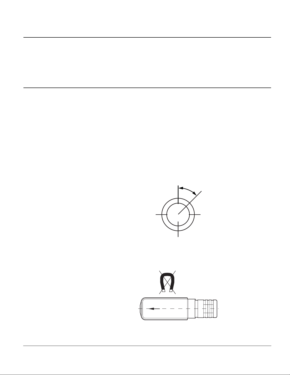
• The nominal installation position of the flow switch is an upright standing position in
horizontal pipework.
• The switches should only be installed in a vertical position with a maximum deviation
of 45°.
m
a
x
.
4
5
°
SEN0531R1
Figure 2. Acceptable Switch Mounting Positions.
• Ensure that there are no external magnetic fields in the immediate vicinity of the flow
switch, since these can impair device operation.
• There is an arrow on the flow switch. Install with the arrow parallel with the pipe
shaft, facing in the flow direction.
SEN0522R1
Figure 3. Flow Direction Arrow.
• The brass connecting nut G¾ has a tightening torque of 18 to 22 lb-ft (25-30 Nm)
Siemens Industry, Inc. Page 3
 Loading...