

Siemens QUADLOG Installation And Service Instructions Manual

Siemens
Energy & Automation, Inc.
SDQLCAI-1
Rev: 4
September 2005
Installation and Service Instruction
QUADLOG
Critical Analog Input Module (CAI)

Trademarks
ProcessSuite, QUADLOG, 4-mation, and APACS+ are trademarks of Siemens Energy & Automation, Inc.
Other names in this publication might be trademarks, the use of which by third parties for their own purposes may
violate the rights of the registered holder.
Copyright Siemens Energy & Automation, Inc. 2005
All rights reserved
The reproduction, transmission or use of this document or
its contents is not permitted without express written
authority. Offenders will be liable for damages. All rights,
including rights created by patent or registration of a utility
model or design, are reserved.
Siemens Energy & Automation, Inc.
1201 Sumneytown Pike
P.O. Box 900
Spring House, PA 19477-0900
Disclaimer of Liability
We have checked the contents of this manual for
agreement with the hardware and software described.
Since deviations cannot be precluded entirely, we cannot
guarantee full agreement. However, the data in this
manual is reviewed regularly and any necessary
corrections included in subsequent editions. Suggestions
for improvement are welcomed.
©Siemens Energy & Automation, Inc. 2005
Technical data subject to change.

SDQLCAI-1 Contents
Table of Contents
Section Title Page
1 Introduction....................................................................................................................1-1
1.1 Product Description......................................................................................................1-1
1.2 Product Support............................................................................................................1-3
1.3 Related Literature.........................................................................................................1-5
2 Installation......................................................................................................................2-1
2.1 Hardware Identification................................................................................................2-1
2.1.1 Module Identification.............................................................................................2-1
2.1.2 Marshalled Termination Assembly Identification..................................................2-2
2.2 Preparations..................................................................................................................2-2
2.3 Environmental Considerations .....................................................................................2-2
2.4 Equipment Delivery and Handling...............................................................................2-3
2.4.1 Predelivery Test .....................................................................................................2-3
2.4.2 Factory Shipment...................................................................................................2-3
2.4.3 Receipt of Shipment...............................................................................................2-3
2.4.4 Return of Equipment within North America..........................................................2-3
2.4.5 Return of Equipment outside North America ........................................................2-4
2.4.6 Equipment Handling and Storage ..........................................................................2-4
2.5 Marshalled Termination Assembly and Cable Installation...........................................2-4
2.5.1 Marshalled Termination Assembly Installation.....................................................2-4
2.5.2 Optional (Flat Surface) Marshalled Termination Assembly Installation...............2-9
2.5.3 Interconnect I/O Cable Installation......................................................................2-10
2.6 CAI Installation ..........................................................................................................2-12
2.6.1 Module Rack Mechanical Keying........................................................................2-14
2.6.2 Module Installation..............................................................................................2-14
2.7 Electrical Installation..................................................................................................2-15
2.7.1 Field Wire Selection.............................................................................................2-16
2.7.2 Marshalled Termination Assembly – I/O Wiring Connections ...........................2-16
2.7.3 Unterminated I/O Cable Assembly Connections.................................................2-19
2.8 Configuration..............................................................................................................2-20
3 Maintenance...................................................................................................................3-1
3.1 Requirements................................................................................................................3-1
3.2 Visual Inspection..........................................................................................................3-1
3.3 Cleaning........................................................................................................................3-1
3.4 Troubleshooting............................................................................................................3-2
3.5 CAI Removal/Replacement..........................................................................................3-3
3.5.1 Removal.................................................................................................................3-3
3.5.2 Replacement...........................................................................................................3-3
3.6 Marshalled Termination Assembly Removal/Replacement.........................................3-4
3.6.1 Removal.................................................................................................................3-4
3.6.2 Replacement...........................................................................................................3-4
3.7 Interconnect I/O Cable Removal/Replacement............................................................3-4
3.7.1 Removal.................................................................................................................3-4
September 2005 i

Contents SDQLCAI-1
3.7.2 Replacement...........................................................................................................3-5
3.8 Spare and Replacement Parts........................................................................................3-5
3.9 Maintenance Records ...................................................................................................3-6
4 Circuit Description ........................................................................................................4-1
4.1 Isolated Power Supply..................................................................................................4-1
4.2 IOBUS Modem.............................................................................................................4-1
4.3 Multiplexers/Converters...............................................................................................4-1
4.4 CPU ..............................................................................................................................4-2
5 Model Designation .........................................................................................................5-1
5.1 Options .........................................................................................................................5-1
5.2 Accessories...................................................................................................................5-2
6 Specifications..................................................................................................................6-1
6.1 Module Specifications..................................................................................................6-1
6.2 Environmental Specifications.......................................................................................6-1
6.3 Electrical Classification................................................................................................6-3
6.3.1 Approvals...............................................................................................................6-3
6.3.2 CSA Hazardous Locations Precautions .................................................................6-3
Index 5
List of Tables
Table Title Page
2–1 Field Wire Selection ......................................................................................................2-16
2–2 Unterminated I/O Cable Assembly................................................................................2-21
3–1 LED Indications...............................................................................................................3-2
5–1 CAI Options.....................................................................................................................5-1
5–2 CAI Accessories ..............................................................................................................5-2
6–1 CAI Specifications...........................................................................................................6-1
6–2 CAI Environmental Specifications..................................................................................6-1
6–3 Agency Approvals For CAI.............................................................................................6-3
List of Illustrations
Figure Title Page
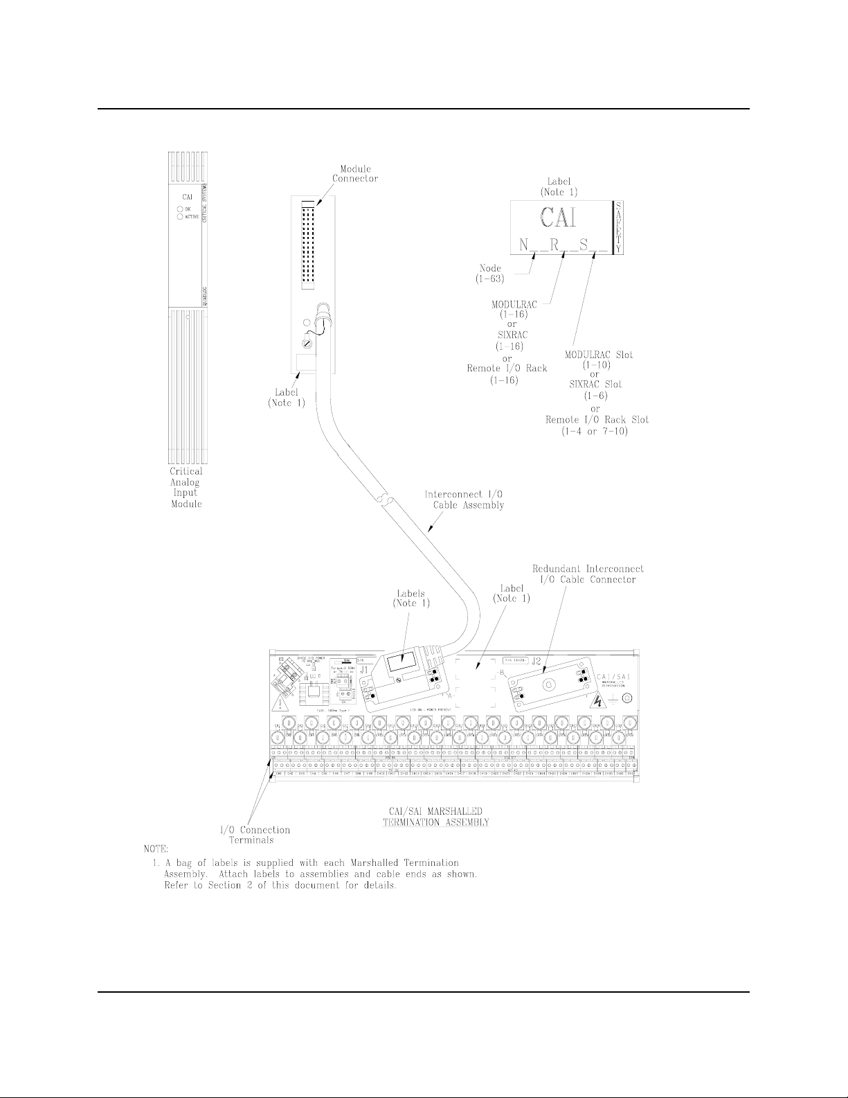
1–1 Critical Analog Input Module (CAI) and Associated Hardware .....................................1-2
2–1 CAI Identification Label..................................................................................................2-1
2–2 Marshalling Utility Panel Dimensions.............................................................................2-6
ii September 2005

SDQLCAI-1 Contents
2–3 Standard CAI/SAI Marshalled Termination Assembly...................................................2-7
2–4 Installing or Removing a Marshalled Termination Assembly.........................................2-8
2–5 Marshalled Termination Assembly Mounting Ear Installation...................................2-9
2–6 Keying an Interconnect I/O Cable Assembly for CAI Use............................................2-11
2–7 Module and Rack Keying ..............................................................................................2-13
2–8 CAI I/O Wiring Connections on Marshalled Resistor Termination Assembly ............2-18
2–9 I/O Supply Monitor Line Connections ..........................................................................2-19
4–1 CAI Block Diagram.........................................................................................................4-2
4–2 CAI Channel Circuit........................................................................................................4-3
Significant Changes for Revision 4
Section Description
Preface (Conventions and Symbols)— new section
1.2 Product Support—contact information updated.
2.7 Electrical Installation—DANGER alert added
3 Maintenance—DANGER alert added
6.3.2 CSA Hazardous Locations Precautions—DANGER alert added
September 2005 iii
Contents SDQLCAI-1
PREFACE
Conventions and Symbols
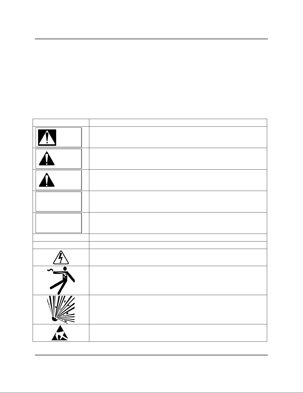
The following symbols may appear in this manual and may be applied to the equipment. The reader
should become familiar with the symbols and their meaning. Symbols are provided to quickly alert the
user to safety related situations, issues, and text.
Symbol Meaning
Indicates an immediate hazardous situation which, if not avoided, will result in
DANGER
death or serious injury.
Indicates a potentially hazardous situation which, if not avoided, could result
WARNING
in death or serious injury.
Indicates a potentially hazardous situation which, if not avoided, may result in
CAUTION
minor or moderate injury.
CAUTION
NOTICE
Important
Note
Indicates a potentially hazardous situation which, if not avoided, may result in
property damage.
Indicates a potential situation which, if not avoided, may result in an
undesirable result or state.
Identifies an action that should be taken to avoid an undesirable result or state.
Identifies additional information that should be read.
Electrical shock hazard. The included Warning text states that the danger of
electrical shock is present.
Electrical shock hazard. Indicated that the danger of electrical shock is
present.
Explosion hazard. Indicates that the danger of an explosion hazard exists.
Electrostatic discharge. The presence of this symbol indicates that
electrostatic discharge can damage the electronic assembly.
iv September 2005
SDQLCAI-1 Contents
Qualified Persons
The described equipment should be installed, configured, operated, and serviced only by qualified persons
thoroughly familiar with this publication. The current version, in Portable Document Format (PDF), is
available at http://sitescape.sea.siemens.com/
.
For the purpose of this publication and product labels, a qualified person is one who is familiar with the
installation, construction, and operation of the equipment, and the involved hazards. In addition, he or she
has the following qualifications:
Is trained and authorized to energize, de-energize, clear, ground and tag circuits and equipment in
accordance with established safety practices.
Is trained in the proper care and use of protective equipment such as rubber gloves, hard hat, safety
glasses or face shields, flash clothing, etc., in accordance with established safety practices.
Is trained in rendering first aid.
Scope
This publication does not purport to cover all details or variations in equipment, nor to provide for every
possible contingency to be met in connection with installation, operation, or maintenance. Should further
information be desired or should particular problems arise which are not covered sufficiently for the
purchaser’s purposes, the matter should be referred to one of the support groups listed in the Product
Support section of this manual.
The contents of this manual shall not become part of or modify any prior or existing agreement,
commitment or relationship. The sales contract contains the entire obligation of Siemens. The warranty
contained in the contract between the parties is the sole warranty of Siemens. Any statements continued
herein do not create new warranties or modify the existing warranty.
General Warnings and Cautions
WARNING
This equipment contains hazardous voltages, and it has been certified for use in the hazardous locations
specified on the product nameplate and in the Model Designation and Specifications section. Death,
serious personal injury, or property damage can result if safety instructions are not followed. Only
qualified personnel should work on or around this equipment after becoming thoroughly familiar with all
warning, safety notices, and maintenance procedures contained herein. The successful and safe operation
of this equipment is dependent upon proper handling, installation, operation, and maintenance.
The perfect and safe operation of the equipment is conditional upon proper transport, proper storage,
installation and assembly, as well as, on careful operation and commissioning.
The equipment may be used only for the purposes specified in this publication.
September 2005 v
Contents SDQLCAI-1
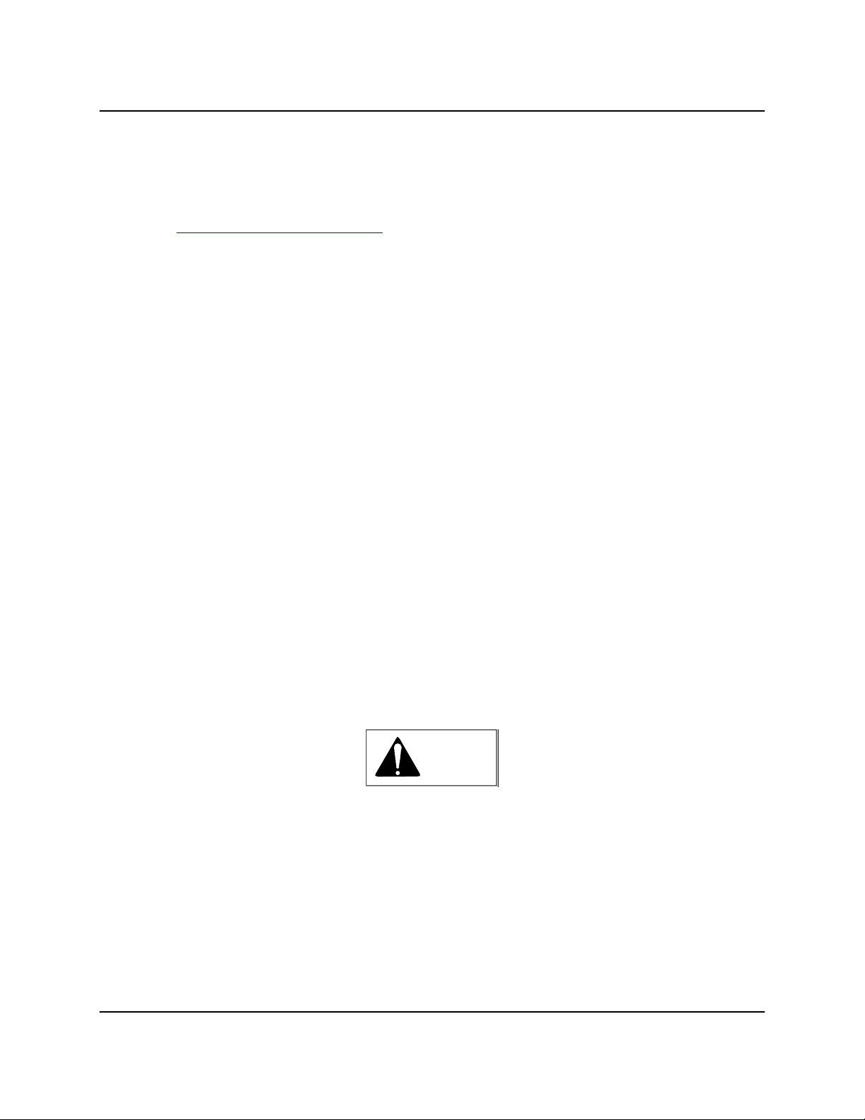
CAUTION
Electrostatic discharge can damage or cause the failure of semiconductor devices such as
integrated circuits and transistors. The symbol at right may appear on a circuit board or other
electronic assembly to indicate that special handling precautions are needed.
A properly grounded conductive wrist strap must be worn whenever an electronics
module or circuit board is handled or touched. A service kit with a wrist strap and static dissipative
mat is available from Siemens (PN15545-110). Equivalent kits are available from both mail order and
local electronic supply companies.
Electronic assemblies must be stored in anti-static protective bags when not installed in equipment.
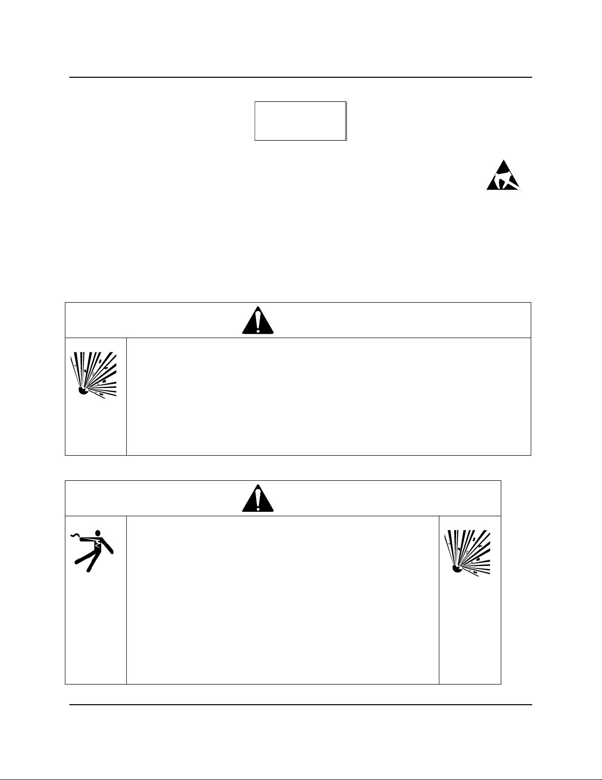
DANGER
Explosion hazard
Will cause death, serious injury or property damage
In potentially hazardous atmosphere, remove power from equipment before
connecting or disconnecting power, signal, or other circuit, or extracting/inserting
module.
Observe all pertinent regulations regarding installation in hazardous area.
Ensure all devices are rated for hazardous (classified) locations.
DANGER
Electrical shock hazard
Explosion hazard
Will cause death, serious injury or property damage
Remove power from all wires and terminals and verify that there
are no hazardous voltages before working on equipment.
In potentially hazardous atmosphere, remove power from
equipment before connecting or disconnecting power, signal, or
other circuit, or extracting/inserting module.
Observe all pertinent regulations regarding installation in
hazardous area.
Ensure all devices are rated for hazardous (classified) locations.
vi September 2005

SDQLCAI-1 Contents
September 2005 vii


SDQLCAI-1 Introduction
1 Introduction
This Instruction provides installation and service information for the QUADLOG Critical Analog Input
Module (CAI) model QLCAIAAN.
It is divided into six major sections as follows:
Section 1, Introduction - Summarizes the information presented in this document. In addition, it
presents a description of the product, provides information about obtaining product support, furnishes
the definitions and usage of international symbols, and supplies a list of related literature.
Section 2, Installation - Describes the mechanical and electrical installation of the product and its
associated signal wire termination hardware. This includes procedures for proper preparation,
identification, and handling of the product. It also lists environmental considerations and provides
overview information about software-based product configuration.
Section 3, Maintenance - Provides information about preventive maintenance, troubleshooting
techniques, assembly replacement, and choosing spare and replacement parts.
Section 4, Circuit Description - Contains a brief block diagram level description of the product. It
explains how the CAI processes I/O signals and operates in conjunction with a control module.
Section 5, Model Designation - Provides model designation and tables of accessories, attachments,
and options.
Section 6, Specifications - Lists the product’s mechanical, electrical, and environmental
specifications.
1.1 Product Description
The QUADLOG Critical Analog Input Module (CAI) is part of the QUADLOG family of safety critical
control and I/O modules. It is ideally suited for such applications as emergency shutdown or burner
management. The CAI uses standard QUADLOG module packaging. It plugs into any of the standard
module racks, where it operates in conjunction with a QUADLOG resource module such as a Critical
Control Module (CCM) as part of a data acquisition and control system. It is an intelligent
(microprocessor-based), configurable I/O module that interfaces 32 channels of analog input signals
between field devices and the IOBUS. The CAI and its associated wiring termination hardware are
shown in Figure 1-1. As shown, field wiring is connected to a remote mounted Marshalled Termination
Assembly. The operating status of the CAI is shown by two bezel-mounted LED indicators.
Using the 4-mation™ Configuration software in conjunction with QUADLOG software configures the
CAI. This software runs on an MS Windows® based personal computer. The configuration is developed
off-line as part of a control module (CCM) configuration. When the configuration is transferred from
4-mation to the control module, the CAI portion is automatically copied from the control module to the
CAI.
May 2002 1-1
Introduction SDQLCAI-1
Figure 1–1 Critical Analog Input Module (CAI) and Associated Hardware
1-2 May 2002

SDQLCAI-1 Introduction
1.2 Product Support
Our Technical Support Centers (TSC) offer a variety of technical support services that are designed to
assist you with Siemens products and systems. Our support engineers have experience with
troubleshooting, development, system startup, and system test. They will help you to solve your issues in
an efficient and professional manner.
Customers in North America can contact Siemens Technical Support Center at 1-800-333-7421, on the
web at: http://support.automation.siemens.com
, or by e-mail: techsupport.sea@siemens.com
Customers outside North America can contact their local Siemens subsidiary; addresses and telephone
numbers are listed on the Internet at the web site: http://support.automation.siemens.com
.
When contacting Siemens, customers will be asked to provide site-contact information (name, address,
and phone number), the product involved and detailed information regarding the nature of the issue.
Product documentation is now located in the Library forum of the Process Automation User Connection
at: http://sitescape.sea.siemens.com/
. The Process Automation User Connection is a secure site.
Registration is open to all verified users of Siemens process automation systems. If you are not already,
and would like to become a member, please visit our Process Automation User Connection web page at:
http://www.sea.siemens.com/process/support/papauc.html
Contained within the Process Automation User Connection is the APACS+/QUADLOG Secure Site at:
http://sitescape.sea.siemens.com/forum/aca-1/dispatch.cgi/f.apacsquadlo
forum. This site is only open to
customers with an active service agreement. It contains all service manuals, service memos, service notes,
configuration manuals, etc. for the APACS+ and QUADLOG family of products. If you are experiencing
technical difficulties with the site, please contact SiteScape technical support at: toll free 1-877-234-1122
(US) or 1-513-336-1474.
May 2002 1-3
Introduction SDQLCAI-1
A&D Technical Support
Worldwide, available 24 hours a day:
Nürnberg
Johnson Cit y
Beijing
United States: Johnson City, TN Worldwide: Nürnberg Asia / Australia: Beijing
Technical Support and Authorization
Local time: Monday to Friday
8:00 AM to 5:00 PM
Telephone:+1 (423) 262 2522
or +1 (800) 333-7421 (USA only)
Fax:+1 (423) 262 2289
Mail to: techsupport.sea@siemens.com
GMT: -5:00
Automation and Drives Service and Support International
http://www.siemens.com/automation/service&support
The languages of the SIMATIC Hotlines and the authorization hotline are generally German and English.
Technical Support
24 hours a day, 365 days a year
Phone:+49 (180) 5050-222
Fax:+49 (180) 5050-223
E-Mail: ad.support@siemens.com
GMT:+1:00
Authorization
Local time: Monday to Friday
8:00 AM to 5:00 PM
Phone: +49 (180) 5050-222
Fax: +49 (180) 5050-223
Mail to: ad.support@siemens.com
GMT: +1:00
Technical Support and Authorization
Local time: Monday to Friday
8:00 AM to 5:00 PM
Phone:+86 10 64 75 75 75
Fax:+86 10 64 74 74 74
Mail to:ad.support.asia@siemens.com
GMT:+8:00
1-4 May 2002

SDQLCAI-1 Introduction
1.3 Related Literature
The following documents are available to complement the installation, configuration, and maintenance of
the CAI. Generally, all needed documentation is supplied with your equipment. It may be supplied in
electronic form in the Adobe portable document format (PDF), printed form, or both. Refer to these
documents as needed or as called for in text. Documents may be located on your workstation’s hard drive
or on a CD supplied with your system.
Using the 4-mation Configuration Software (document number CG39-20)
QUADLOG I/O Module Configuration (document number CGQL-4)
QUADLOG CCM/ACM+ Standard Function Blocks (document number CGQL-3)
MODULPAC 1000 Installation and Service Instruction (document number SD39MODULPAC-1)
May 2002 1-5

Introduction SDQLCAI-1
1-6 May 2002
SDQLCAI-1 Installation
2 Installation
This section describes installation of the Critical Analog Input Module (CAI) and its associated I/O
wiring termination hardware. Review and complete the preparatory steps in section 2.2 before proceeding
with the installation.
IMPORTANT
The CAI installation should be in accordance with the National Electrical
Code (NEC), other applicable construction, and electrical codes.
The CAI is only to be used for the purposes described by Siemens.
2.1 Hardware Identification
2.1.1 Module Identification
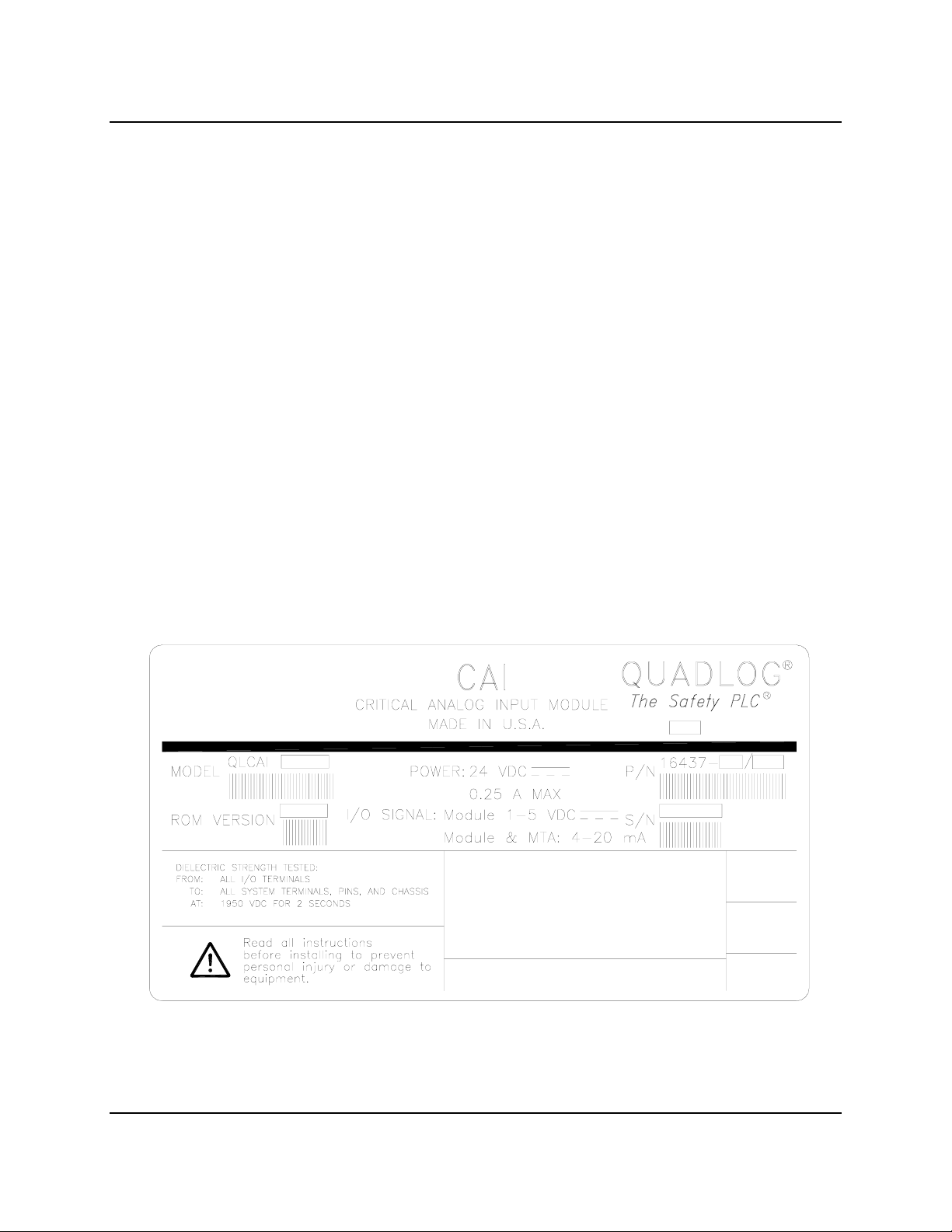
The CAI is identified by the three-letter “CAI” designation on the bezel and by two nameplate labels.
One nameplate label is large, similar to that shown in Figure 2-1, and located on the left side of the
module. A smaller label is located inside the bezel compartment. Both labels contain the CAI’s model
designation, part number/issue level, ROM version number, and serial number (S/N). The larger label
also lists the power requirements, and space is provided for information such as agency certifications.
SIEMENS
Siemens Energy & Automation, Inc.
Figure 2–1 CAI Identification Label
May 2002 2-1

Installation SDQLCAI-1
2.1.2 Marshalled Termination Assembly Identification
The CAI can be used with the CAI/SAI Marshalled Termination Assembly. This assembly is identified
by the following information printed on its surface.
CAI/SAI
MARSHALLED
TERMINATION
P/N 16428-1
2.2 Preparations
1. Install the MODULRAC (SIXRAC, or Remote I/O Rack) in the cabinet where the CAI is to be
installed. The CAI should not be installed in the rack at this time; however, its designated slot
number should be known.
2. If remote I/O termination is employed, complete the following tasks:
If Marshalling Utility Panels are being used, install them in their respective marshalling cabinets.
Tag all I/O cables and route them into the marshalling cabinet. They should be ready for cable
end preparation and connection to the CAI/SAI Marshalled Termination Assemblies. Cable wire
sizes: 24 to 12 AWG.
Route the Interconnect I/O Cable (or Unterminated I/O Cable) between the rack in which the CAI
is to be installed and the marshalling cabinet. Refer to Figure 1-1; the J1 end of the cable is to be
installed in the rack and P2 end is to be connected to the appropriate Marshalled Termination
Assembly in the marshalling cabinet.
If an Unterminated I/O Cable is installed, you must supply and install the appropriate termination
hardware (terminal blocks) for field signal I/O wiring and the I/O Cable.
3. If channel diagnostics are to be used for automatically detecting wiring faults such as short or open
circuits, each channel must be wired with the appropriate resistors (and configured accordingly).
High-power EMI-producing equipment should not be connected to any power lines dedicated to CAI
input signals.
2.3 Environmental Considerations
Many industrial environments create severe operating conditions. The conditions at each CAI
location must be within the specifications stated in section 6.2.
To ensure operator safety, Marshalled Termination Assemblies shall be installed in enclosures, which
require a key or special tool to gain access to the equipment.
2-2 May 2002
 Loading...