

Siemens Q Series,QFA3100,QFA3101,QFA3160,QFA3160D,QFA3171,QFA4160,QFA4160D,QFA3171D,QFA4171D,QFA4171 Technical Instructions
Q-Series
Relative Humidity and
Relative Humidity &
Temperature Sensors for
Critical Environments
and Outdoor Air
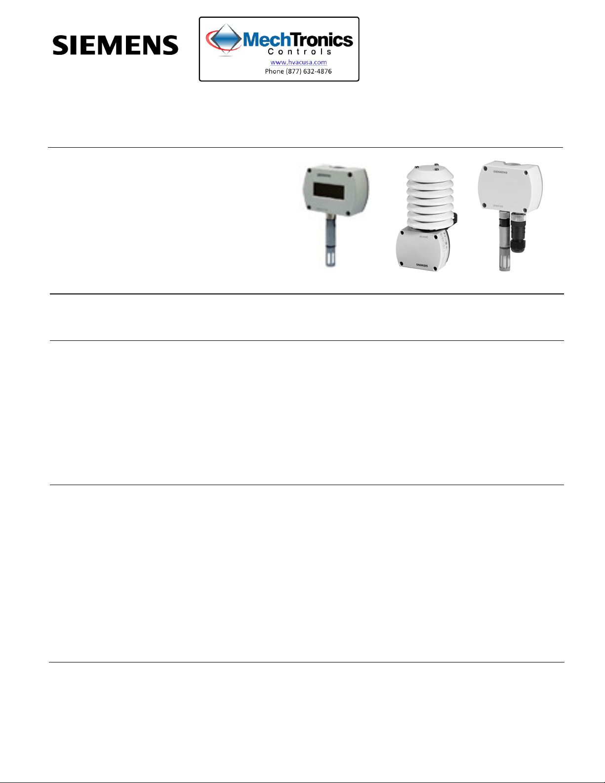
Description
The Q-Series Relative Humidity and Relative Humidity & Temperature Sensors for
Critical Environments and Outdoor Air monitor and transmit changes in humidity and
temperature to the building control systems.
Technical Instructions
Document No. 155-755
February 28, 2013
Features
Application
• Operating voltage 24 Vac/13.5 to 35 Vdc
• Signal output 0 to 10 Vdc/4 to 20 mA for relative humidity and temperature
• Very high measuring accuracy across the entire measuring range
• Capacitive humidity measurement
• Precise, stable humidity sensing
• Available in 2% and 2%, certified models
• Optional display
• Recalibration service available (QFA41 Series only)
The Q-Series Outdoor Air rh and rh/T Sensors are for use in HVAC applications where
high accuracy and short response times for measuring relative humidity are required.
The measuring range covers the entire humidity range of 0 to 100%. Some application
examples:
• Storage and production facilities in the paper, textile, pharmaceutical, food, chemical
and electronics industry, etc.
• Laboratories
• Hospitals
• Computer and EDP centers
• Greenhouses
• Outdoor use requires AQF3100 Outdoor Mounting Kit
Siemens Industry, Inc.
Technical Instructions Q-Series Outdoor Air and Critical Environment
Document Number 155-755 Relative Humidity and Relative Humidity & Temperature Sensors
February 28, 2013
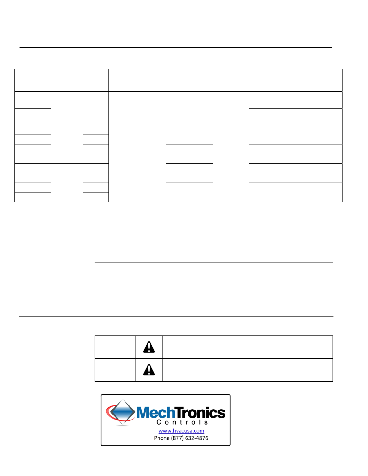
Product Numbers
Product
Number
QFA3100
QFA3101
QFA3160
QFA3160D Yes
QFA3171 None
QFA3171D
QFA4160 None
QFA4160D Yes
QFA4171 None
QFA4171D
Accessories
Accuracy Display Temperature
Measuring Range
None None
None
2%
Field selectable:
32°F to 122°F
Yes
(0°C to 50°C),
-31°F to 95°F
(-35°C to 35°C), or
2%,
certified
-40°F to 158°F
(-40°C to 70°C)
Yes
74 662 01040 US rigid 1/2-inch conduit adapter
AQF3101 Sensor filter cap (replacement)
Table 1.
Temperature
Signal Output
Active,
0 to 10 Vdc
Active,
4 to 20 mA
Active,
0 to 10 Vdc
Active,
4 to 20 mA
Humidity
Measuring
Range
0 to 100%
Humidity
Signal Output
Active,
0 to 10 Vdc
Active,
4 to 20 mA
Active,
0 to 10 Vdc
Active,
4 to 20 mA
Active,
0 to 10 Vdc
Active,
4 to 20 mA
Operating
Voltage
24 Vac or 13.5
to 35 Vdc
13.5 to 35 Vdc
24 Vac or 13.5
to 35 Vdc
13.5 to 35 Vdc
24 Vac or 13.5
to 35 Vdc
13.5 to 35 Vdc
AQF3150 Replaceable, 2% sensor tip
AQF4150 Replaceable, certified sensor tip
AQF3100 Outdoor Mounting Kit (including sun shield)
Outdoor Mounting Kit
The Outdoor Mounting Kit consists of:
AQF3100
• One wall mounting bracket complete with sun shield
• Four Phillips-head screws, K35 × 12
• One grommet M 16 × 1.5 with O-ring and nut M 16 × 1.5 for closing off the sensor's
cable entry hole if not required.
Warning/Caution Notations
WARNING:
CAUTION:
Personal injury, or loss of life may occur if you do not perform
a procedure as specified.
Equipment damage may occur if you do not perform a
procedure as specified.
Page 2 Siemens Industry, Inc.

Q-Series Outdoor Air and Critical Environment Technical Instructions
Relative Humidity and Relative Humidity & Temperature Sensors Document Number 155-755
February 28, 2013
Ordering
Information
Equipment
Combinations
Technical Design
Relative Humidity
Temperature
Resistive Load Diagram
The AQF3100 outdoor mounting kit listed under Accessories must be ordered as a
separate item.
The circular connector with its screwed plug is delivered uninstalled (QFA4160).
The Q-Series Relative Humidity and Relative Humidity & Temperature Sensors can be
used with all types of systems and devices that can acquire and handle the sensor’s 0
to 10 Vdc or 4 to 20 mA output signal.
The sensor acquires relative humidity via its capacitive sensing element; the
capacitance varies as a function of the relative humidity of the ambient air. An electronic
circuit converts the sensor's signal to a continuous 0 to 10 Vdc or 4 to 20 mA signal,
which corresponds to a relative humidity of 0 to 100%.
The sensor acquires the temperature via its sensing element; the electrical resistance
varies according to the temperature of the ambient air.
This variation is converted to an active 0 to 10 Vdc or 4 to 20 mA output signal,
corresponding to a temperature range of 32°F to 122°F, -31°F to 95°F, or -40°F to
158°F (0°C to 50°C, -35°C to 35°C, or -40°C to 70°C). The measuring range is selected
by repositioning factory-supplied jumpers.
Figure 1. Output Signal, Terminal I1/I2.
Mechanical Design
Siemens Industry, Inc. Page 3
The room sensor consists of housing, printed circuit board, connection terminals and
measuring rod. The housing consists of two parts: base and removable cover
(screwed). The QFA4160 also has a circular connector.
The measuring circuit and the setting element are located inside the cover of the printed
circuit board; the connection terminals are in the base. The housing and measuring rod
are screwed together.
The sensing elements are located at the end of the measuring rod and are protected by
a screw-on filter cap.
For the QFA31 Series, the M16 cable entry gland supplied with the sensor can be
screwed into the bottom of the base. If the sensor is used outdoors, that opening must
be closed off and the prepared hole on the opposite side of the base knocked out.
For the QFA41 Series, the cable entry is made via the circular connector, which
consists of a coupling piece with M16 thread and a connector with a screwed plug. The
coupling piece is secured to the housing and internally wired. The sensor is designed
for wall mounting.
 Loading...