

Page 1
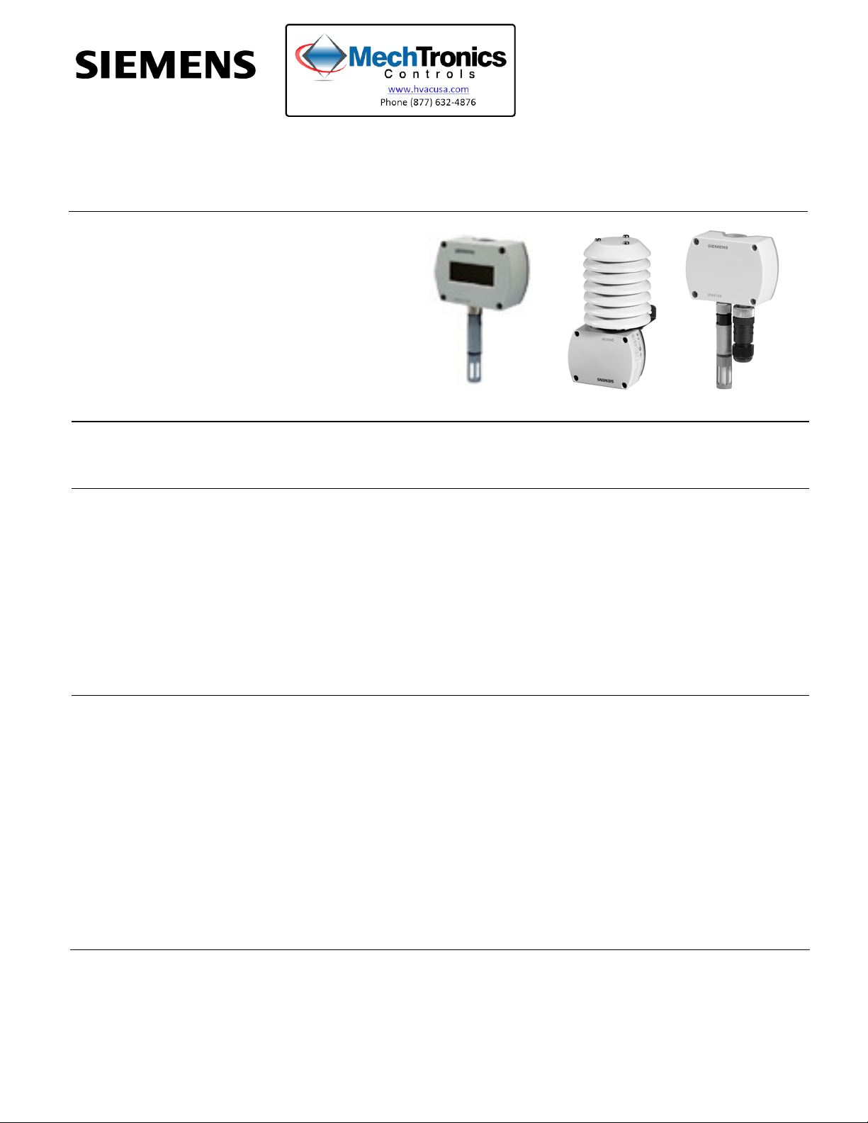
Q-Series
Relative Humidity and
Relative Humidity &
Temperature Sensors for
Critical Environments
and Outdoor Air
Description
The Q-Series Relative Humidity and Relative Humidity & Temperature Sensors for
Critical Environments and Outdoor Air monitor and transmit changes in humidity and
temperature to the building control systems.
Technical Instructions
Document No. 155-755
February 28, 2013
Features
Application
• Operating voltage 24 Vac/13.5 to 35 Vdc
• Signal output 0 to 10 Vdc/4 to 20 mA for relative humidity and temperature
• Very high measuring accuracy across the entire measuring range
• Capacitive humidity measurement
• Precise, stable humidity sensing
• Available in 2% and 2%, certified models
• Optional display
• Recalibration service available (QFA41 Series only)
The Q-Series Outdoor Air rh and rh/T Sensors are for use in HVAC applications where
high accuracy and short response times for measuring relative humidity are required.
The measuring range covers the entire humidity range of 0 to 100%. Some application
examples:
• Storage and production facilities in the paper, textile, pharmaceutical, food, chemical
and electronics industry, etc.
• Laboratories
• Hospitals
• Computer and EDP centers
• Greenhouses
• Outdoor use requires AQF3100 Outdoor Mounting Kit
Siemens Industry, Inc.
Page 2
Technical Instructions Q-Series Outdoor Air and Critical Environment
Document Number 155-755 Relative Humidity and Relative Humidity & Temperature Sensors
February 28, 2013
Product Numbers
Product
Number
QFA3100
QFA3101
QFA3160
QFA3160D Yes
QFA3171 None
QFA3171D
QFA4160 None
QFA4160D Yes
QFA4171 None
QFA4171D
Accessories
Accuracy Display Temperature
Measuring Range
None None
None
2%
Field selectable:
32°F to 122°F
Yes
(0°C to 50°C),
-31°F to 95°F
(-35°C to 35°C), or
2%,
certified
-40°F to 158°F
(-40°C to 70°C)
Yes
74 662 01040 US rigid 1/2-inch conduit adapter
AQF3101 Sensor filter cap (replacement)
Table 1.
Temperature
Signal Output
Active,
0 to 10 Vdc
Active,
4 to 20 mA
Active,
0 to 10 Vdc
Active,
4 to 20 mA
Humidity
Measuring
Range
0 to 100%
Humidity
Signal Output
Active,
0 to 10 Vdc
Active,
4 to 20 mA
Active,
0 to 10 Vdc
Active,
4 to 20 mA
Active,
0 to 10 Vdc
Active,
4 to 20 mA
Operating
Voltage
24 Vac or 13.5
to 35 Vdc
13.5 to 35 Vdc
24 Vac or 13.5
to 35 Vdc
13.5 to 35 Vdc
24 Vac or 13.5
to 35 Vdc
13.5 to 35 Vdc
AQF3150 Replaceable, 2% sensor tip
AQF4150 Replaceable, certified sensor tip
AQF3100 Outdoor Mounting Kit (including sun shield)
Outdoor Mounting Kit
The Outdoor Mounting Kit consists of:
AQF3100
• One wall mounting bracket complete with sun shield
• Four Phillips-head screws, K35 × 12
• One grommet M 16 × 1.5 with O-ring and nut M 16 × 1.5 for closing off the sensor's
cable entry hole if not required.
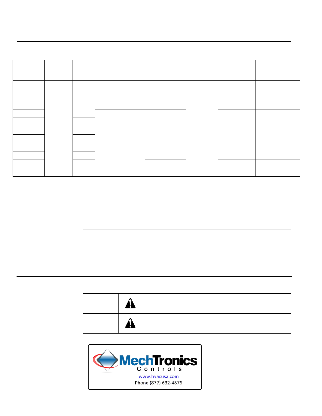
Warning/Caution Notations
WARNING:
CAUTION:
Personal injury, or loss of life may occur if you do not perform
a procedure as specified.
Equipment damage may occur if you do not perform a
procedure as specified.
Page 2 Siemens Industry, Inc.
Page 3

Q-Series Outdoor Air and Critical Environment Technical Instructions
Relative Humidity and Relative Humidity & Temperature Sensors Document Number 155-755
February 28, 2013
Ordering
Information
Equipment
Combinations
Technical Design
Relative Humidity
Temperature
Resistive Load Diagram
The AQF3100 outdoor mounting kit listed under Accessories must be ordered as a
separate item.
The circular connector with its screwed plug is delivered uninstalled (QFA4160).
The Q-Series Relative Humidity and Relative Humidity & Temperature Sensors can be
used with all types of systems and devices that can acquire and handle the sensor’s 0
to 10 Vdc or 4 to 20 mA output signal.
The sensor acquires relative humidity via its capacitive sensing element; the
capacitance varies as a function of the relative humidity of the ambient air. An electronic
circuit converts the sensor's signal to a continuous 0 to 10 Vdc or 4 to 20 mA signal,
which corresponds to a relative humidity of 0 to 100%.
The sensor acquires the temperature via its sensing element; the electrical resistance
varies according to the temperature of the ambient air.
This variation is converted to an active 0 to 10 Vdc or 4 to 20 mA output signal,
corresponding to a temperature range of 32°F to 122°F, -31°F to 95°F, or -40°F to
158°F (0°C to 50°C, -35°C to 35°C, or -40°C to 70°C). The measuring range is selected
by repositioning factory-supplied jumpers.
Figure 1. Output Signal, Terminal I1/I2.
Mechanical Design
Siemens Industry, Inc. Page 3
The room sensor consists of housing, printed circuit board, connection terminals and
measuring rod. The housing consists of two parts: base and removable cover
(screwed). The QFA4160 also has a circular connector.
The measuring circuit and the setting element are located inside the cover of the printed
circuit board; the connection terminals are in the base. The housing and measuring rod
are screwed together.
The sensing elements are located at the end of the measuring rod and are protected by
a screw-on filter cap.
For the QFA31 Series, the M16 cable entry gland supplied with the sensor can be
screwed into the bottom of the base. If the sensor is used outdoors, that opening must
be closed off and the prepared hole on the opposite side of the base knocked out.
For the QFA41 Series, the cable entry is made via the circular connector, which
consists of a coupling piece with M16 thread and a connector with a screwed plug. The
coupling piece is secured to the housing and internally wired. The sensor is designed
for wall mounting.
Page 4

Technical Instructions Q-Series Outdoor Air and Critical Environment
Document Number 155-755 Relative Humidity and Relative Humidity & Temperature Sensors
February 28, 2013
Setting Element
Figure 2. Configuring the Jumpers.
The setting element is located inside the cover. It consists of six pins and a jumper.
They are used to select the required temperature measuring range and to activate the
test function. The different jumper positions have the following meanings:
• For the active (0 to 10V or 4 to 20 mA) temperature measuring range with the
jumper in the:
Left position (1) = -31°F to 95°F (-35°C to 35°C)
Mid position (2) = 32°F to 122°F (0°C to 50°C) (factory setting)
Right position (3) = -40°F to 158°F (-40°C to 70°C)
Behavior in the Event of
a Fault
Calibration Certificates
(QFA41 Series only)
Engineering Notes
Cable Routing and Cable
Selection
• For the active test function:
Jumper in the horizontal position: See
Figure 2. Jumper Settings for Signal Output
Ranges for the values available at the signal output.
• If the temperature sensor is faulty, the voltage at signal output U2 (I2) is 0V (4 mA)
after 60 seconds. The humidity signal at signal output U1 (I1) increases to 10V
(20 mA).
• If the humidity sensor is faulty, the voltage at signal output U1 (I1) is 10V (20 mA)
after 60 seconds. The temperature signal remains active
The sensor and its exchangeable AQF4150 measuring tip are numbered, registered
and calibrated prior to delivery. The associated calibration certificates are supplied with
the sensor.
• Use a safety extra low-voltage (SELV) transformer with separate windings designed
for 100% duty.
• Observe all local and national safety regulations when sizing and protecting the
transformer.
• Take the sensor's power consumption into consideration when sizing the
transformer.
• See the devices' Installation Instructions for the sensor's electrical connection.
• Observe the maximum permissible cable lengths.
Electrical interference increases the longer the cables run parallel and the smaller the
distance is between them. Use shielded cables if necessary. Twisted pairs of cables are
required for the secondary supply lines and the signal lines.
Page 4 Siemens Industry, Inc.
Page 5

Q-Series Outdoor Air and Critical Environment Technical Instructions
Relative Humidity and Relative Humidity & Temperature Sensors Document Number 155-755
February 28, 2013
Mounting Notes
Interior Mounting for
QFA31 Series without
AQF3100
Mounting Position
• Mount on an inside wall (not on outside wall) of the room to be air-conditioned. Do
not mount in recesses, shelves, behind curtains, above or close to heat sources; or
on walls behind which a chimney is located.
• Do not expose the sensor to direct sunlight.
• Install the sensor in an occupied space approximately five feet (1.5 m) above the
floor and at least 20 inches (50 cm) from the next wall.
CAUTION:
• Do not remove the seal between the housing and cover. The degree of
protection IP 65 will be no longer ensured if the seal is removed.
• Avoid any impact while mounting. The sensing elements inside the
measuring rod are sensitive to shock and impact.
The sensor must be mounted with the measuring rod pointing downward for the QFA41
Series or the QFA31 Series (without the AQF3100 Outdoor Mounting Kit).
Mounting Instructions
Outdoor Mounting for
QFA31 Series with
AQF3100
Mounting Location
Mounting Position
Mounting Instructions
Commissioning
Notes
Recalibration
Service
(QFA41 Series only)
Installation Instructions are printed on the sensor's packaging
Mount on an exterior wall, preferably on the north or northwest side of the building. If
possible, mount in the middle of the wall, at least 8 feet (2.5 meters) above the ground.
Do not mount above or below windows, above doors or ventilation shafts, or below
balconies or eaves.
The sensor and AQF3100 must be mounted in a vertical position (with the sun shield at
the top).
NOTE: When using the AQF3100 outdoor mounting kit, the sensor's cable entry hole
must be closed off with the grommet and the prepared M16 cable entry on the
opposite side knocked out.
Installation Instructions are printed on the sensor's packaging
• Check the wiring before switching on power.
• Select the required temperature measuring range on the sensor.
Siemens Industry, Inc. provides a recalibration service for used sensors. Recalibration
should be performed at 12-month intervals under normal conditions (that is within the
comfort range for humidity and temperature and at air contamination levels that are not
above average). Recalibration requires the purchase of a new sensor tip (part number
AQF4150).
Services Provided
Siemens Industry, Inc. Page 5
The recalibration service includes the following:
• Delivery and invoicing of the new AQF4150 measuring tip, complete with calibration
certificate.
• Delivery of a calibration certificate for the (old) measuring tip returned to Siemens
Building Technologies, Inc. enabling the customer to assess the time of usage of the
measuring.
Page 6

Technical Instructions Q-Series Outdoor Air and Critical Environment
Document Number 155-755 Relative Humidity and Relative Humidity & Temperature Sensors
February 28, 2013
Specifications
Operating voltage 24 Vac
+ 20% or 13.5 to 35 Vdc
Frequency 50/60 Hz at 24 Vac
Power Supply
Humidity element
Power consumption
< 1 VA
Operating range 0 to 100% rh
Measurement range 0 to 95% rh
Accuracy at room temperature (73°F [20°C])
+ 2% rh, 0 to 95% rh
Time constant Approx. 20 s in moving air
Output signal, linear (terminal U1) 0 to 10 Vdc = 0 to 100% rh
Max.
+ 1 mA
Operating temperature -40°F to 158°F (-40°C to 70°C)
Temperature effect < 0.1% per degree Celsius
Sensing element Capacitive humidity sensing element
Output signal (rh only units) 4 to 20 mA or 0 to 10 Vdc, 0 to 100%
linear, proportional
Output signal (rh/T units) 4 to 20 mA or 0 to 10 Vdc, 0 to 100%
linear, proportional
Polarity protection Yes
Temperature element
(for combination rh/T
units only)
Operating temperature, jumper selectable 32°F to 122°F (0°C to 50°C) or
-31°F to 95°F (-35°C to 35°C),
-40°F to 158°F (-40°C to 70°C)
Time constant @ 32°F to 122°F Approximately 20 s in moving air
(0°C to 50°C) and 10 to 80% rh
General
Agency certification
Accuracy
@ 32°F to 122°F (0°C to 50°C)
@ -31°F to 95°F (-35°C to 35°C)
@ 32°F to 158°F (0°C to 70°C)
+ 1.8°F (+ 1°C)
+ 1.4°F (+ 0.8°C)
+ 1.8°F (+ 1°C)
Output signal 4 to 20 mA or 0 to 10 Vdc, 0 to 100%
linear, proportional
Calibration adjustments None
Installation 18 AWG cable length shared in
conduit with other sensor wiring.
750 ft (229 m) maximum
Connections Screw terminals
Dimensions
Outdoor air probe 6" OD × 3.3" L (15 mm × 84 mm)
Outdoor air housing 3.1" L × 2.3" W × 1.5" D
(80 mm × 60 mm × 40 mm)
Shield (mounted) 3.43" H × 3.5" W × 4.1" D
(87 mm × 89 mm × 104 mm)
Voltage requirement 13.5 to 35 Vdc
Material type Polycarbonate plastic
Protection class rating IP 65 (NEMA 4)
Conforms to EMC Directive 89/336/EEC
UL Listing UL873 XAPX
cUL Listing Canadian Standard C22.2 No. 24-93
Conforms to Australian EMC Radio Communication Act 1992
Framework Radio Interference Emission AS/NZS 3548
Standard
Page 6 Siemens Industry, Inc.
Page 7

Q-Series Outdoor Air and Critical Environment Technical Instructions
Relative Humidity and Relative Humidity & Temperature Sensors Document Number 155-755
February 28, 2013
Wiring Terminals
QFA3100 QFA3101 QFA3160/QFA3160D/
QFA4160/QFA4160D
Figure 3. Wiring Terminals.
QFA3171/QFA3171D/
QFA4171/QFA4171D
QFA4160/QFA4160D Front View: Connector
fitted, body removed
Figure 4. Connectors.
QFA4171/QFA4171D Front View:
Connector fitted, body removed
Dimensions
Figure 5. QFA31 Series Sensors with AQF3100 Dimensions in Inches
(Millimeters).
Siemens Industry, Inc. Page 7
Page 8

Technical Instructions Q-Series Outdoor Air and Critical Environment
Document Number 155-755 Relative Humidity and Relative Humidity & Temperature Sensors
February 28, 2013
Dimensions,
Continued
Figure 6. QFA31 Series Dimensions in Inches (Millimeters).
Figure 7. QFA41 Series Sensors Dimensions in Inches (Millimeters).
Information in this publication is based on current specifications. The company reserves the right to make changes in specifications and models as
design improvements are introduced. Product or company names mentioned herein may be the trademarks of their respective owners.
© 2013 Siemens Industry, Inc.
Siemens Industry, Inc.
Building Technologies Division
1000 Deerfield Parkway
Buffalo Grove, IL 60089
USA
+ 1 847-215-1000
Your feedback is important to us. If you have
comments about this document, please send them
to SBT_technical.editor.us.sbt@siemens.com
Document No. 155-755
Printed in the USA
Page 8
 Loading...