

Page 1
p
Flame Detectors
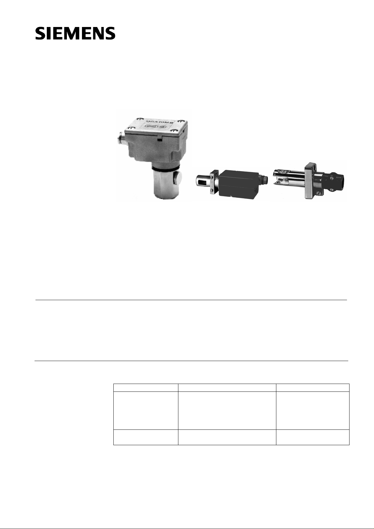
QRA10... QRA53..., QRA55... with clamp QRA2... with clam
7
QRA2...
712
The flame detectors are designed for use with Siemens burner controls, for the
supervision of gas or oil flames.
The QRA... and this Data Sheet are intended for use by OEMs which integrate the
flame detectors in their products.
Use
The flame detectors are used for the supervision of gas flames, yellow- or blue-burning
oil flames and for ignition spark proving.
Type reference For use with burner control type Operating mode
QRA2..., QRA10... LGB2... / LGB4... with AGQ1...
LFL...
LFE1...
LFE10...
LMG... with AGQ2...
QRA53..., QRA55... LGK16...
LGI16...
QRA10...
QRA53...
QRA55...
Intermittent
Continuous
CC1N7712en
17.01.2005
Siemens Building Technologies
HVAC Products
Page 2

Warning notes
Mounting notes
Installation notes
To avoid injury to persons, damage to property or the environment, the following
warning notes should be observed!
• All activities (mounting, installation and service work, etc.) must be performed by
qualified staff
• Before making any wiring changes in the connection area of the detector, completely isolate the equipment from the mains supply (all-polar disconnection)
• Ensure protection against electric shock h azard by providing adequate protection
for the terminals
• Check to ensure that wiring is in an orderly state
• Halogen lamps, welding equipment, special lamps or ignition sparks may produce
sufficient radiation for the detector’s UV cell to ignite. X-rays and gamma radiation
can also generate erroneous flame signals
• Fall or shock can adversely affect the safety functions. Such units must not be put
into operation, even if they do not exhibit any damage
• Ensure that the relevant national safety regulations are complied with
• Always run the high-voltage ignition cables separate while observing the greatest
possible distance to the detector and to other cables
Electrical connection of the flame detector
It is important to achieve practically disturbance- and loss-free signal transmission:
• Never run the detector cable together with other cables
– Line capacitance reduces the magnitude of the flame signal
– Use a separate cable
• Observe the permissible lengths of the detector cable (refer to «Technical data»)
2/8
Siemens Building Technologies CC1N7712en
HVAC Products 17.01.2005
Page 3
Commissioning notes
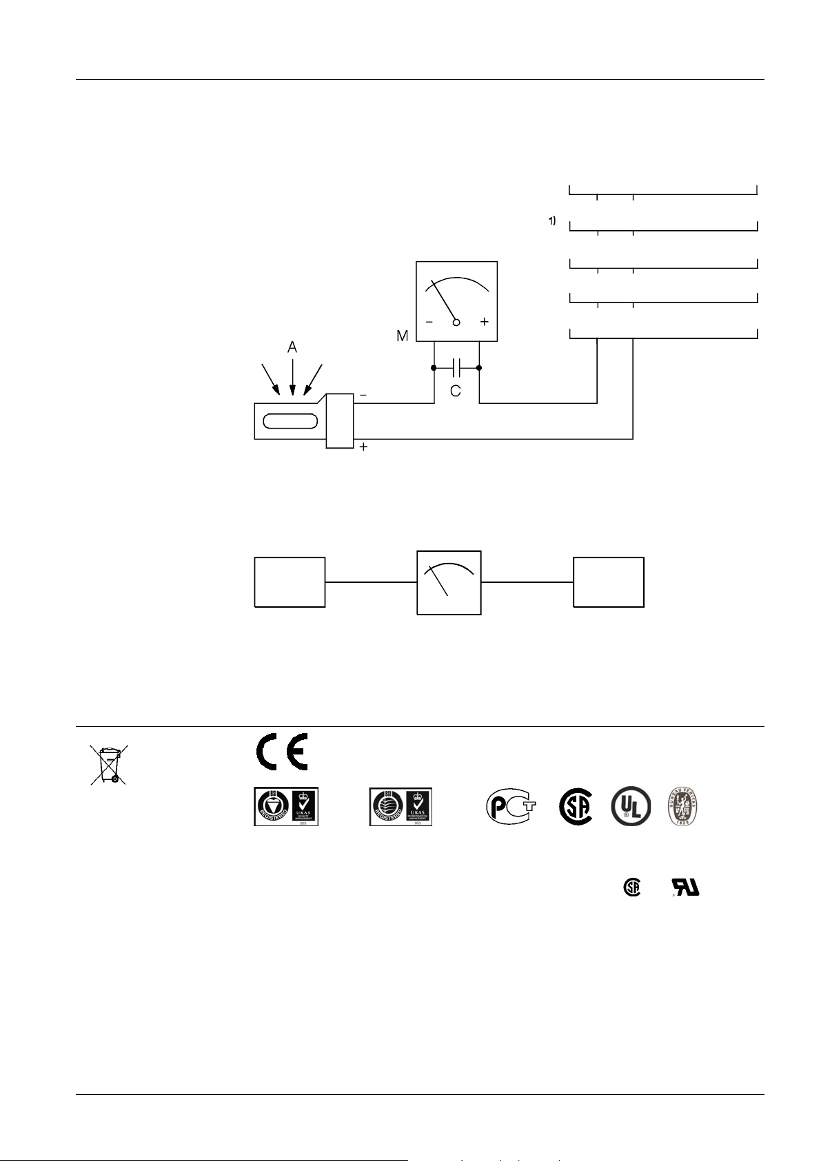
Measuring circuit for
QRA2..., QRA10... and
QRA5...of the D-series
• Prior to commissioning, ensure that wiring is in an orderly state
• Trouble-free burner operation is ensured only when the intensity of UV radiation at
the detector’s location is high enough for the detector’s UV cell to ignite during
each half wave. The intensity of UV radiation at the detector’s location is
checked through measurement of the detector current
10
9
sw
bl
AGQ1... / AGQ2...
LFE10...
Legend
Measuring circuit for
QRA5... up to the
C-series
23
22
22
23
13
15
LGK16...
LFL1...
LFE1...
7712v01/1001
1) Connection of microammeter across AGQ1... / AGQ2... adapter and flame detector
A Incidence of radiation
M Microammeter (DC), internal resistance ≤ 5000 Ω
C Electrolytic capacitor 100...470 µF, DC 10...25 V
QRA53
QRA55 LGI16...
-+
KF8832
M
AGM19
LGK16...
7712v03/9602
Minimum detector current values required:
Refer to the Data Sheet of the relevant burner control or to the Operating Instructions of
the KF8832.
Certificates
Conformity to EEC directives
- Electromagnetic compatibility EMC (immunity)
89 / 336 EEC
ISO 9001: 2000
Cert. 00739
ISO 14001: 1996
Cert. 38233
Valid for QRA2...
For applications in U.S. / Canada, the flame detectors carry the
Siemens Building Technologies CC1N7712en
HVAC Products 17.01.2005
and markings.
3/8
Page 4
Service notes
A
Disposal notes
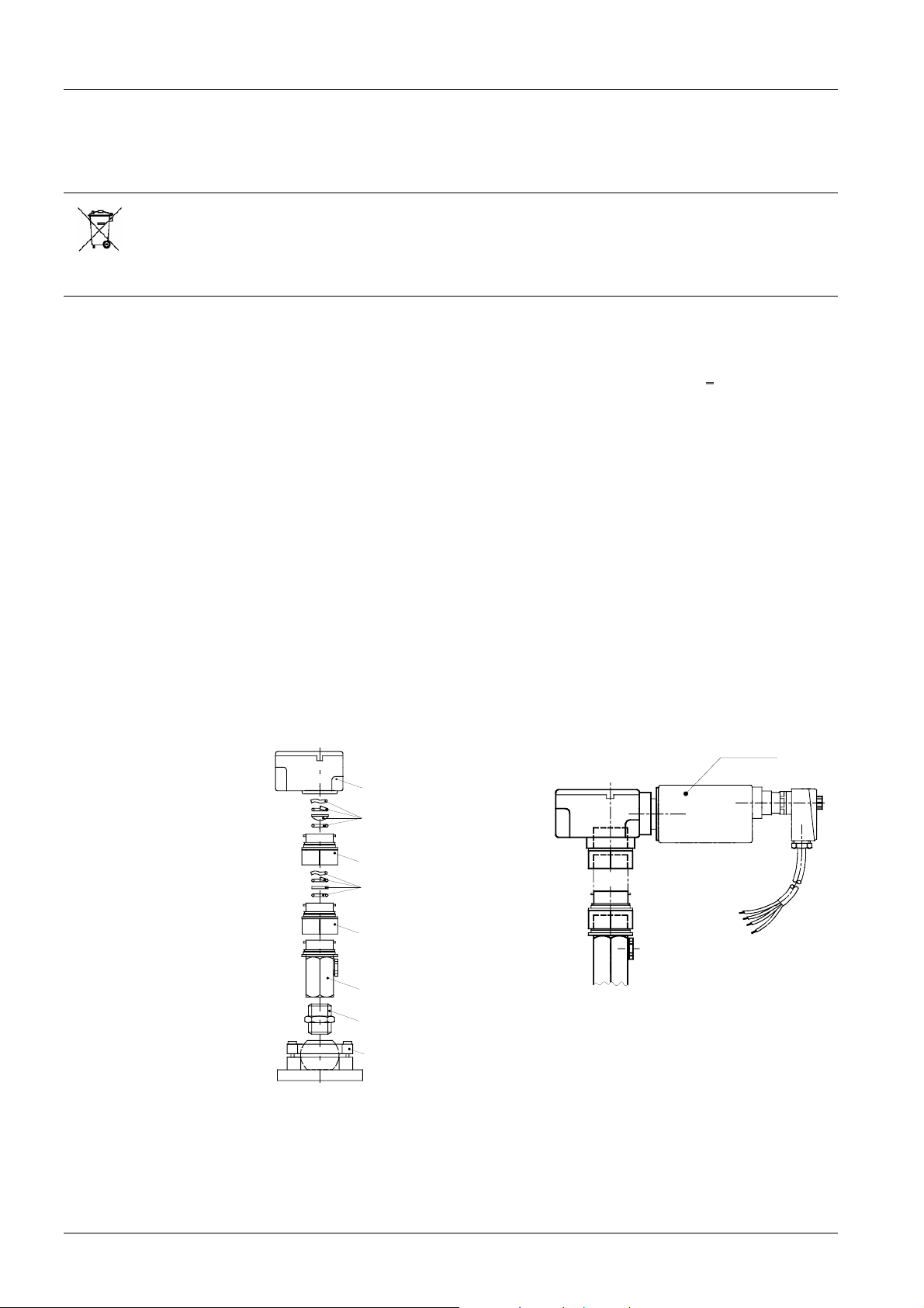
Mechanical design
Flame detectors
QRA2...
Flame detectors
QRA10...
Flame detectors
QRA5...
Plug AGM19
dapter AGG16.C
• Each time a flame detector has been replaced, check to ensure that wiring is in an
orderly state
• Use the KF8832 service unit for short periods of time only
The flame detector contains electrical and electronic components and must not be disposed of together with domestic waste.
Local and currently valid legislation must be observed.
Plastic housing, metalized to prevent static charging caused by the air flow from the
fan. For direct mounting on the burner. The detectors can be supplied with or without
securing flange and clamp (refer to «Type summary»).
Die-cast aluminium housing with a 1 in. mounting coupling (D) and a
connection facility
for cooling air. The housing of this detector has a bayonet fitting which allows it to be
secured either directly to the 1 in. mounting coupling or to the AGG06 glass holder. The
1 in. mounting coupling can be screwed to a viewing tube or to the AGG07 ball head.
The Pg cable gland can be removed and replaced, if some other detector cable shall be
used.
The detector’s UV cell is located behind a swiveling shutter at the front end of the detector tube which is flanged to the housing. A quartz-glass window protects the tube
and the shutter against dirt. The detector’s housing accommodates a stepper motor to
drive the shutter and the electronics to control the shutter. Using the AGG16.C adapter,
this flame detector can be mounted either directly on the burner, on a viewing tube or
on a combustion chamber viewing hole.
AGM19 complete with cable for the connection of QRA53... and QRA55... flame detectors.
AGG16.C for QRA53..., QRA55..., made of die-cast aluminium with a 1 in. mounting
coupling. The 1 in. mounting coupling (D) is attached to the housing with a bayonet
fitting.
QRA5...
AGG16.C
AGG03
7712m08/0797
7712z05/0403
AGG06
AGG02
AGG06
D
AGG05
AGG07
QRA5... with AGG16.C and AGG06
Note
AGG03 or AGG02 can also be fitted in the 1 in. mounting coupling (D) of the AGG16.C
(or QRA10...). An adapter combination with AGG06 glass holder, mounting coupling
and ball joint for QRA53..., QRA55... and QRA10... is possible.
4/8
Siemens Building Technologies CC1N7712en
HVAC Products 17.01.2005
Page 5
Glass and quartz-glass
A
A
lens holder AGG06
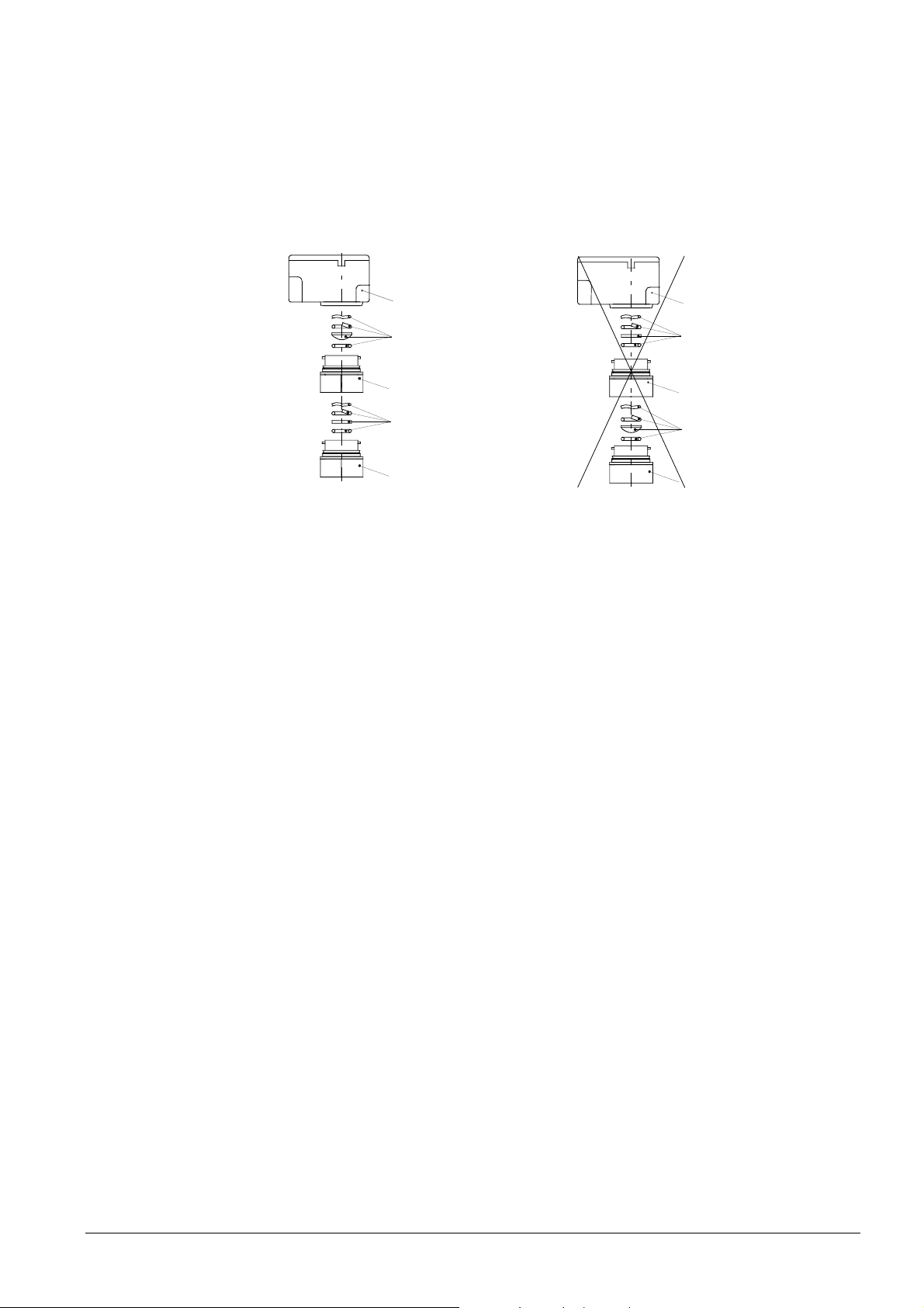
The glass and quartz-glass lens holder AGG06 serves for holding the AGG03 lens and
the AGG02 heat insulation glass.
The lens is used to increase the sensitivity, and the heat insulation glass provides protection against high temperatures, thus extending the life of the UV cell.
The AGG06 also allows various combinations of lens, heat insulation glass and 1 in.
mounting coupling.
When using the lens and the heat insulation glass, the AGG06 with the lens must be
mounted as close as possible to the flame detector.
Quartz-glass lens
GG03
Heat insulation glass
GG02
Mounting coupling (D)
Nipple AGG05
Ball head AGG07
AGG16.C
AGG03
!
AGG06
AGG02
7712z06/0403
Correct Wrong
AGG06 has a bayonet fitting with which it is attached either to the housing of the
AGG16.C or to the housing of the QRA10... and the 1 in. mounting coupling.
By undoing the bayonet fittings on both sides, the AGG06 glass holder(s) can be easily
detached from the combination of QRA10... or AGG16.C and QRA53... or QRA55....
This facilitates straightforward cleaning of the glass or lens without having to remove
them from the AGG06 glass holder.
The intermediate rings are used for the smooth running of the bayonet fittings, especially where – after removal of the flame detector – the hole to the combustion chamber serves as a viewing tube.
By fitting the intermediate ring to the appropriate bayonet connection, the combination
can be undone where required by rotating the housing of the QRA10... or AGG16.C
AGG03 with spring washer and O-ring for increasing the sensitivity.
AGG02 with spring washer and O-ring, offering the same mounting choices as the
AGG03.
This heat insulation glass is required on applications where the temperature at the
flame detector exceeds 80 °C.
Using the bayonet fitting, the 1 in. mounting coupling can be attached either to the
AGG06, the AGG16.C or the QRA10... flame detector.
The mounting coupling is supplied with the QRA10... or AGG16.C.
1 in. nipple AGG05 for connecting the 1 in. mounting coupling (D) to the AGG07 ball
head.
AGG07 with 1 in. internal thread.
Connection on AGG05 and for use with the 1 in. mounting coupling and the AGG06.
The AGG07 is used for mounting on a rigid surface, such as the boiler wall.
It facilitates optimum adjustment of the viewing angle.
AGG06
!
7712z07/0403
AGG16.C
AGG02
AGG06
AGG03
AGG06
5/8
Siemens Building Technologies CC1N7712en
HVAC Products 17.01.2005
Page 6
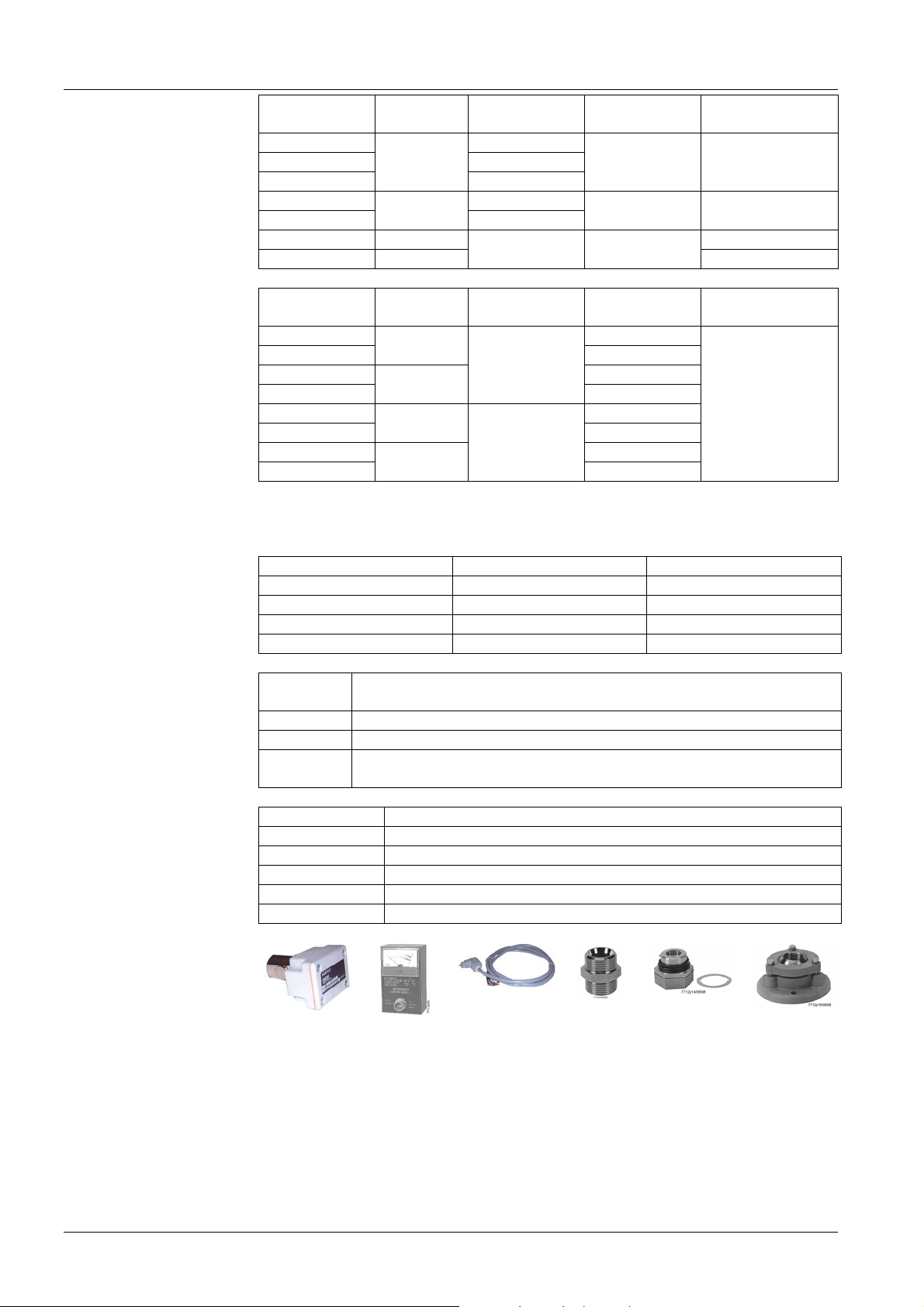
Type summary
A
A
A
Flame detectors
Note
ccessories for QRA2...
and QRA5... when
ordered as single items
ccessories for QRA5...
ccessories for
QRA10... and AGG16.C
Type reference Sensitivity Flange and
Terminal cover Spare UV tube
clamp
QRA2
QRA2(1)
QRA2.9 ²)
QRA2M
QRA2M(1)
QRA10.C
QRA10M.C
Normal
High
Normal ARG4 502 1131 0
High
Without
With
Black
Without
Without
Green ARG4 502 4065 7
With
--- ---
ARG4 502 1131 0
ARG4 502 4065 7
Type reference Sensitivity Detector tube
Mains voltage Spare UV tube
length
QRA53.C27
QRA53.C17
QRA53.D27
QRA53.D17
QRA55.C27
QRA55.C17
QRA55.D27
QRA55.D17
Normal
High
Normal
High
125 mm
77 mm
AC 220...240 V
AC 100...110 V
AC 220...240 V
AC 100...110 V
AC 220...240 V
AC 100...110 V
AC 220...240 V
AC 100...110 V
ARG4 502 4065 7
All QRA5... are delivered complete with clamp. Use of the detector requires a connecting cable AGM19 (refer to «Accessories» for QRA5...).
Part For use with Part number
Flange ³) rounded QRA2...
Flange straight QRA2...
Clamp ³) QRA2...
Clamp for direct mounting 4) QRA5...
4 241 8855 0
4 241 8898 0
4 199 8806 0
4 199 1034 0
Type
Description
reference
AGG16.C
AGM19
KF8832
Adapter for flame detector mounting QRA53... and QRA55...
Connecting cable (2 m) with plug for QRA53..., QRA55...
Unit for measuring the detector current with QRA53... and QRA55...,
recommended for use with detector types up to the C-series
Type reference Description
AGG02
AGG03 1)
AGG05
AGG06
AGG07
Heat insulation glass with spring washer and O-ring
Quartz-glass lens with spring washer and O-ring
1 in. nipple
Glass and quartz-glass lens holder with intermediate ring
Ball head with 1 in. internal thread, angular range 14°
AGG16.C KF8832 AGM19 AGG05 AGG06 with
intermediate ring
AGG07
Legend
6/8
Siemens Building Technologies CC1N7712en
HVAC Products 17.01.2005
1) For detectors of the B-series, lens AGG01 is available
2) With heat-resistant housing for ambient temperatur es up to 20 0 °C (sh or t-time, up to a few seconds)
3) Supplied with QRA2...(1) types
4) Supplied with QRA5... types
Page 7

Ordering
Technical data
General detector data
Environmental
conditions
When ordering, please give type references according to «Type summary».
Average life of UV cell approx. 10,000 hours at max. 50 °C,
higher ambient temperatures reduce
considerably the cell’s life
Perm. combustion chamber pressure
- QRA10...
- QRA10... + AGG03 or AGG02
Degree of protection
- QRA2...
- QRA10...
- QRA53..., QRA55...
max. 50 mbar
max. 500 mbar
IP 40
IP 54
IP 54
Mounting position optional
Weight
- AGG01
- AGG02
- AGG03
- AGG05
- AGG06
- AGG07
- AGG16.C
- QRA2...
- QRA10...
- QRA10... + AGG03
- QRA53..., QRA55...
approx. 10 g
approx. 10 g
approx. 10 g
approx. 170 g
approx. 160 g
approx. 1330 g
approx. 650 g
approx. 60 g
approx. 740 g
approx. 750 g
approx. 900 g
Ignition cable (only QRA2...) 2 x 0.75 mm²; 5.1 mm dia.
Storage
DIN EN 60721-3-1
Climatic conditions class 1K3
Mechanical conditions class 1M2
Temperature range -20...+60 °C
Humidity < 95 % r.h.
Transport
Climatic conditions
Mechanical conditions
Temperature range
Humidity
Operation
Climatic conditions
Mechanical conditions
Temperature range
Humidity
DIN EN 60 721-3-2
class 2K2
class 2M2
-20...+60 °C
< 95 % r.h.
DIN EN 60 721-3-3
class 3K3
class 3M3
-20...+60 °C
< 95 % r.h.
Condensation, formation of ice and ingress of water are not permitted!
Function
With this type of flame supervision, the UV radiation emitted by gas or oil flames is
used to generate the flame signal.
The radiation detector consists of a UV-sensitive cell with 2 electrodes, which ignite
when illuminated with radiation in the 190...270 nm range of the spectrum, thereby
triggering a current in the flame detector circuit.
The UV cell does not respond to glowing firebrick in the combustion chamber, daylight
or light from boiler room illumination.
7/8
Siemens Building Technologies CC1N7712en
HVAC Products 17.01.2005
Page 8
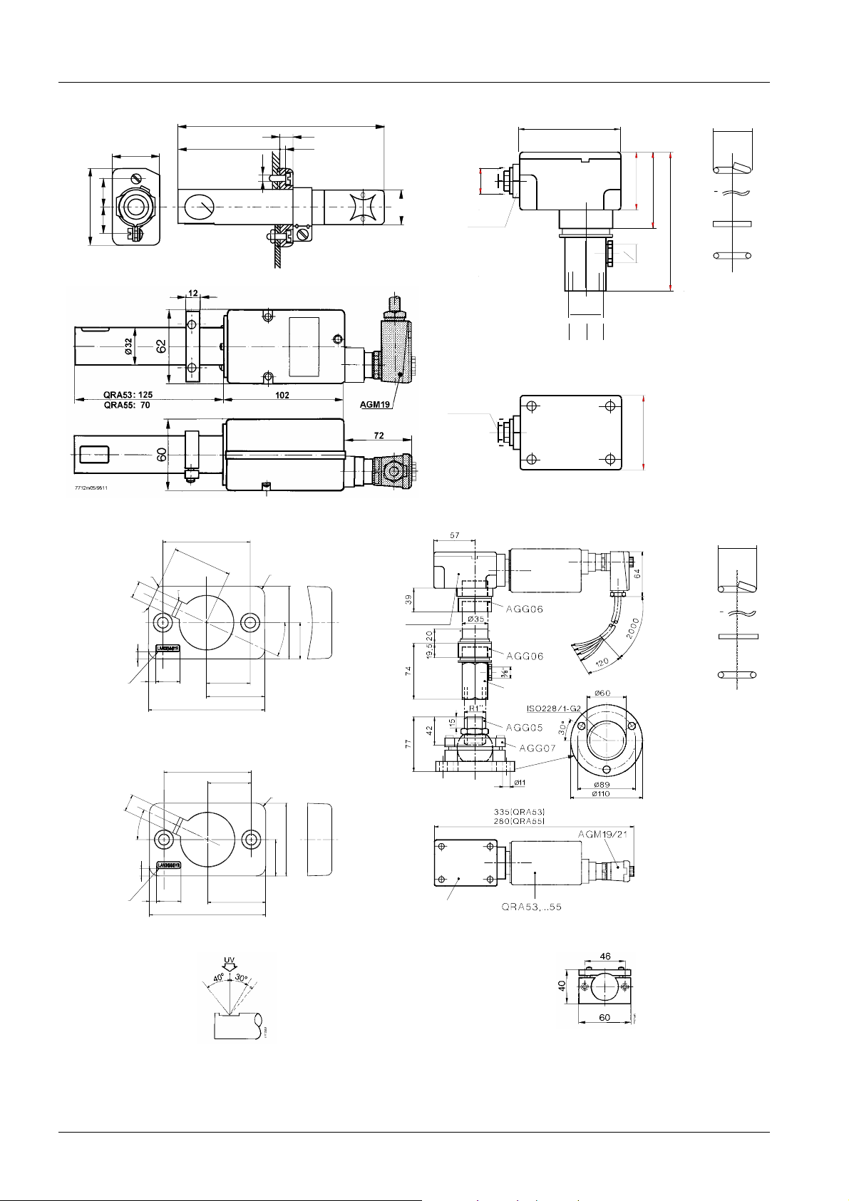
Dimensions
Dimensions in mm
30
18
48
18
QRA2... QRA10... AGG02
25...50 2,5
QRA5...
M4
97
10
SW20
22,5
7712m07/0597
SW22
87
52
66
120
'
'
8
3
R1
''
22,8
7712M04
Company logo to
LN 3 8380 0102
0.2 mm elevated
Company logo to
LN 3 8380 0102
0.2 mm elevated
UV
7712m02/0997
Pg13,5
65
4 241 88550 QRA5... with AGG05, AGG06, AGG07, AGG16.C and AGM19 AGG03
36
2
4
.
3
R2
7
R2
3
3
4 241 8898 0
7
°
5
2
3
310
R0.3
10
18
48
36
18
48
R4
30
°
5
2
15
7712m09e/1001
24
R4
30
15
7712m10e/1001
24
AGG16.C
AGG16.C
D
7712m01/0403
Incidence of radiation Clamp for direct mounting on the burner or the AGG16.C
22,8
7712M03
8/8
Siemens Building Technologies CC1N7712en
HVAC Products 17.01.2005
©2005 Siemens Building Technologies HVAC Products GmbH
Subject to change!
 Loading...