

Siemens QMX3.P37, QMX3.P34, QMX3.P02, QMX3.P74, QMX3.P30 Technical Principles
...
s Infrastructure & Cities
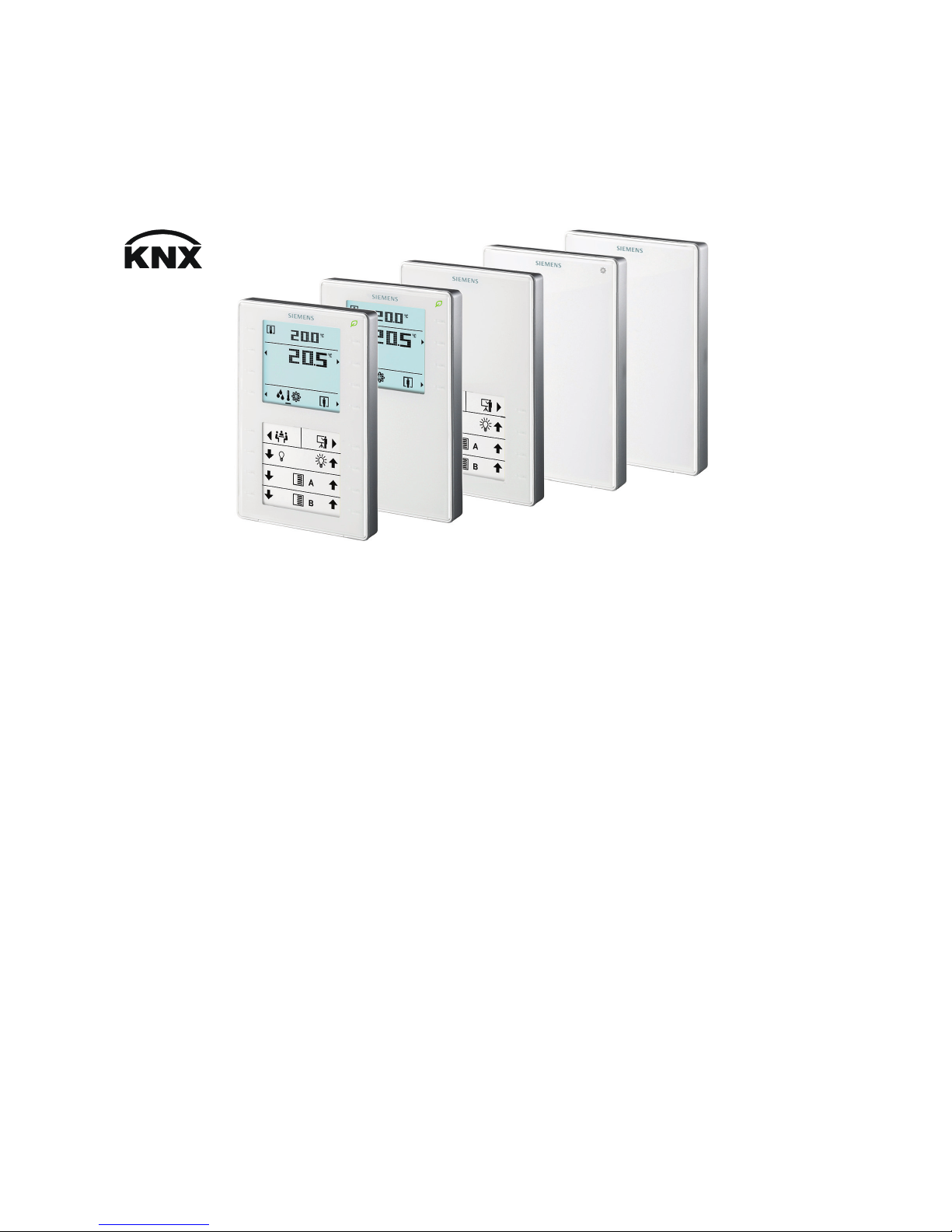
QMX3.P37 QMX3.P34 / P74 QMX3.P02 QMX3.P70 QMX3.P30
Wall-mounted sensors and room operator units for
KNX S-Mode and KNX LTE-Mode
Technical principles
CM2N1602en_01
2013-07-04
Building Technologies

2 / 40
Siemens Wall-mounted sensors and room operator units for KNX S-Mode and KNX LTE-Mode CM2N1602en_01
Building Technologies Contents 2013-07-04
Contents
1
About this document .............................................................................. 4
1.1 Revision history ......................................................................................... 4
1.2 Before you start ......................................................................................... 4
1.2.1 Trademarks ............................................................................................... 4
1.2.2 Copyright ................................................................................................... 4
1.2.3 Quality assurance ..................................................................................... 4
1.2.4 Use of documents/ Request to the reader ................................................ 4
1.3 Abbreviations and naming conventions .................................................... 5
1.3.1 Abbreviations ............................................................................................ 5
1.3.2 Naming convention ................................................................................... 5
1.4 Reference documents ............................................................................... 5
2 Devices ..................................................................................................... 6
2.1 Type summary ........................................................................................... 6
2.2 Equipment combinations ........................................................................... 6
2.3 Variant and device parts ............................................................................ 7
2.4 Service and connection elements ............................................................. 8
2.5 Dimensions................................................................................................ 9
2.6 Environmental compatibility, disposal ..................................................... 10
3 Safety and EMC optimization ............................................................... 10
3.1 Notes on safety ....................................................................................... 10
3.2 Device-specific regulations ..................................................................... 10
3.3 Notes on EMC optimization..................................................................... 11
4 Mounting and electrical installation .................................................... 12
5 Functionality / Use ................................................................................ 15
5.1 Basics ...................................................................................................... 15
5.1.1 System environment ............................................................................... 15
5.1.2 Engineering and commissioning documentation .................................... 15
5.2 Overview ................................................................................................. 16
5.3 Use .......................................................................................................... 17
5.4 Display elements and buttons ................................................................. 18
5.5 Functions ................................................................................................. 19
5.5.1 Measuring................................................................................................ 19
5.5.2 Control and operation .............................................................................. 20
5.6 Application examples .............................................................................. 23
5.6.1 Room temperature control and operation via QMX3 .............................. 23
5.6.2 Presence dependent room climate control with operation of all disciplines24
5.6.3 Room temperature, humidity and air quality control ............................... 25

3 / 40
Siemens Wall-mounted sensors and room operator units for KNX S-Mode and KNX LTE-Mode CM2N1602en_01
Building Technologies Contents 2013-07-04
6
GAMMA building management system .............................................. 26
6.1 Engineering ............................................................................................. 26
6.2 Commissioning........................................................................................ 26
6.3 KNX S-Mode communication objects ..................................................... 27
6.4 KNX S-Mode Parameter description ....................................................... 31
6.4.1 Room temperature sensor ...................................................................... 31
6.4.2 Room temperature control ...................................................................... 31
6.4.3 Room relative humidity sensor ................................................................ 32
6.4.4 Room relative humidity control ................................................................ 32
6.4.5 Room air quality sensor .......................................................................... 33
6.4.6 Room air quality control .......................................................................... 33
6.4.7 Device display parameters ...................................................................... 33
6.4.8 HVAC operation and display ................................................................... 34
6.4.9 Operation and display: Relative humidity visualization ........................... 34
6.4.10 Display on QMX3.P70 Air quality indication LED .................................... 34
6.4.11 Operation and display: air quality............................................................ 34
6.4.12 Operation of light, shading and scenes .................................................. 35
6.5 Examples for the functionality of touch keys and display elements ........ 36
7 Synco building automation and control system ................................ 38
7.1 Engineering ............................................................................................. 38
7.2 Commissioning........................................................................................ 38
7.3 Parameter description ............................................................................. 40
7.3.1 Communication ....................................................................................... 40
7.3.2 Universal temperature sensor ................................................................. 40
7.3.3 Room humidity sensor ............................................................................ 40
7.3.4 Room air quality sensor .......................................................................... 40

4/40
Siemens Wall-mounted sensors and room operator units for KNX S-Mode and KNX LTE-Mode CM2N1602en_01
Building Technologies About this document 2013-07-04
1 About this document
1.1 Revision history
Revision
Date
Changes
Section
Pages
_01
July 2013
First edition
1.2 Before you start
1.2.1 Trademarks
The trademarks used in this document and their lawful owners are listed in the
table below.. The use of trademarks is subject to international and domestic
provisions of the law.
Trademark(s)
Legal owner
KNX® KNX Association, B - 1831 Brussels-Diegem Belgium
http://www.knx.org/
All product names listed in the table are registered (®) or not registered (™)
trademarks of the owner listed in the table. These trademarks will not be indicated
elsewhere in the text (e.g. by use of symbols such as ® and ™) due to the
reference in this Section and to facilitate the reading of the text,
1.2.2 Copyright
This document may be duplicated and distributed only with the express permission
of Siemens, and may be passed only to authorized persons or companies with the
required technical knowledge.
1.2.3 Quality assurance
These documents were prepared with great care.
• The contents of all documents are checked at regular intervals.
• All necessary corrections are included in subsequent versions.
• Documents are automatically amended as a consequence of modifications and
corrections to the products described.
Please make sure that you are aware of the latest document revision date.
If you find any lack of clarity while using this document, or if you have any
criticisms or suggestions, please contact your local POC at the nearest branch
office. Addresses for Siemens RCs are available at www.siemens.com/sbt
1.2.4 Use of documents/ Request to the reader
Before using our products, it is important that you read the documents supplied
with or ordered at the same time as the products (equipment, applications, tools
etc.) carefully and in full.
We assume that persons using our products and documents are authorized and
trained appropriately and have the technical knowledge required to use our
products as intended.

5/40
Siemens Wall-mounted sensors and room operator units for KNX S-Mode and KNX LTE-Mode CM2N1602en_01
Building Technologies About this document 2013-07-04
For more details on the products and applications, please refer to:
• On the internet: "Technical product data and descriptions" at
www.siemens.com/gamma-td
• On the intranet (for Siemens employees only) at
http://step.bt.siemens.com/portal/index.html
• At your next Siemens branch office www.siemens.com/sbt
or at your system
suppliers.
• From the support team in the headquarters fieldsupport-
zug.ch.sbt@siemens.com if no local POC is available.
Siemens assumes no liability to the extent allowed under the law for any losses
resulting from a failure to comply with the aforementioned points or for the improper
compliance of the same.
1.3 Abbreviations and naming conventions
1.3.1 Abbreviations
Abbr.
Description
ACS790
Engineering Tool for Synco devices (KNX LTE-Mode)
ETS
Engineering Tool Software (KNX S-Mode) http://www.knx.org/
KNX LTE-Mode
Communication with KNX LTE-Mode (Logical Tag Extended Mode)
KNX S-Mode
Communication with KNX
1.3.2 Naming convention
The term "room operator unit" in this document always refers to all types:
QMX3.P02. P30. P34, P70 und P74.
1.4 Reference documents
The following documents are available at http://www.siemens.com/bt/download
[1] Data sheet N1602
[2] Mounting instructions M1692
[3] Word template for labels (QMX3.P02, P37) M1602.1
[4] KNX bus (CE1N3127
)
[5] KNX Standard, Volume 3: System Specifications, Part 7, Chapter 2: Data
Point Types (http://www.knx.org/
)
[6] Service- and Operating software ACS790 (CE1N5649
)
6 / 40
Siemens Wall-mounted sensors and room operator units for KNX S-Mode and KNX LTE-Mode CM2N1602en_01
Building Technologies Devices 2013-07-04
2 Devices
2.1 Type summary
Product number Stock number
Features
Temperature
sensor
Sensor for
humidity and CO
2
Air quality indicator
with LED
Segmented backlit
display and
touchkeys
Parameterizable
touchkeys with
LED display
Window for labels
Sensors
QMX3.P30
S55624-H103
X
QMX3.P70
S55624-H104
X X X
Room
operator
units
QMX3.P02
S55624-H107
X X X
QMX3.P34
S55624-H105
X X
QMX3.P74
S55624-H106
X X X
QMX3.P37
S55624-H108
X X X X
2.2 Equipment combinations
The room operator units are KNX certified and can be connected to all suitable
KNX devices, if the appropriate communication objects are available in the
application.
Use in the following BAC systems:
• GAMMA Building Management Systems / third-party devices (KNX S-Mode)
• Building automation and control systems with KNX S-mode
Integration of third-party devices and free configuration.
• Synco700
KNX LTE can only use the sensor information of types QMX3.P30 and
QMX3.P70.
• Desigo TRA
The devices can be used with all series room automation stations.
7 / 40
Siemens Wall-mounted sensors and room operator units for KNX S-Mode and KNX LTE-Mode CM2N1602en_01
Building Technologies Devices 2013-07-04
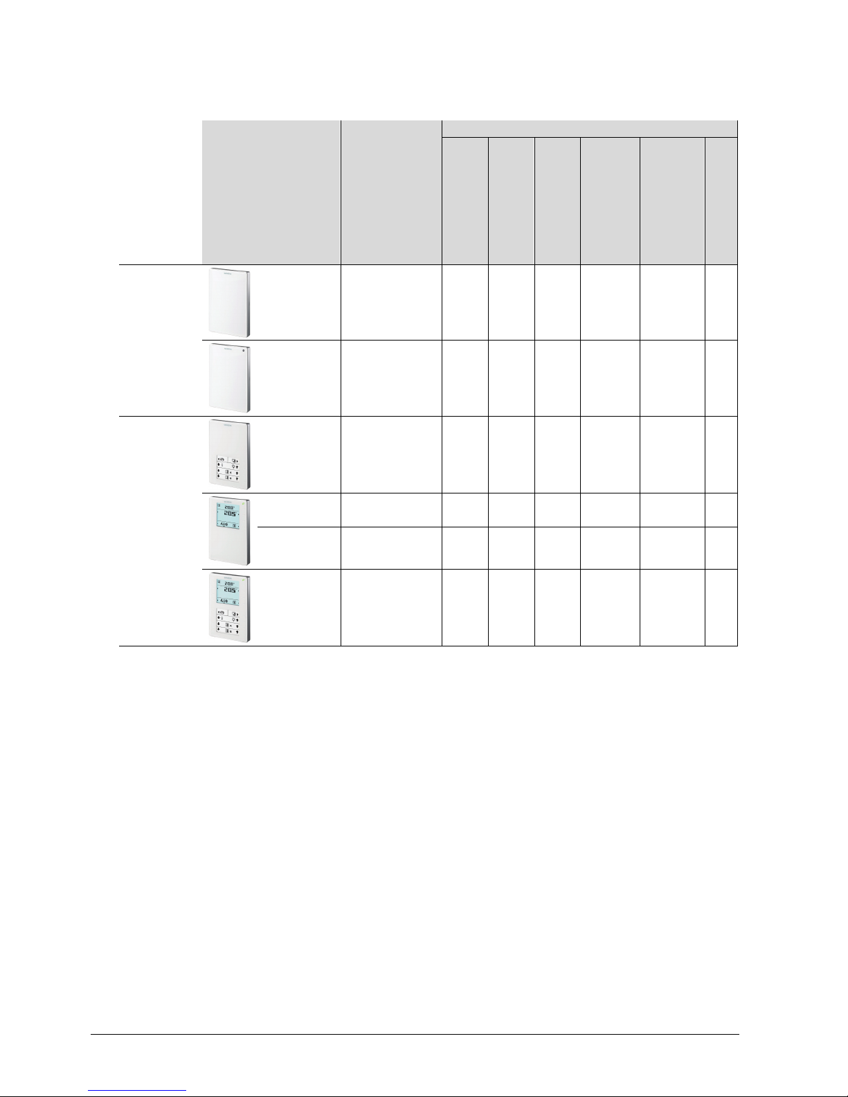
2.3 Variant and device parts
2602J01
B
C
A
• The devices are designed for wall-mounting (A). A conduit box is optional.
– Conduit box: Keep in mind the dimensions of the conduit box!
– Cable conduits on the wall: Keep a distance of 30 mm (from above) /
20 mm (from below) to the base plate (B), so that the device (C) can be
snapped onto the base plate.
• The base plate (B) has screw holes for all common flush-mount boxes.
The screw head height must not exceed 3 mm.
• The device (C) incorporates a KNX plug, and, depending on the type, sensor
element, keys, LCD panel, window for the label.
The cable can be pushed into channels on the rear.
• A KNX plug is enclosed with the devices
8 / 40
Siemens Wall-mounted sensors and room operator units for KNX S-Mode and KNX LTE-Mode CM2N1602en_01
Building Technologies Devices 2013-07-04
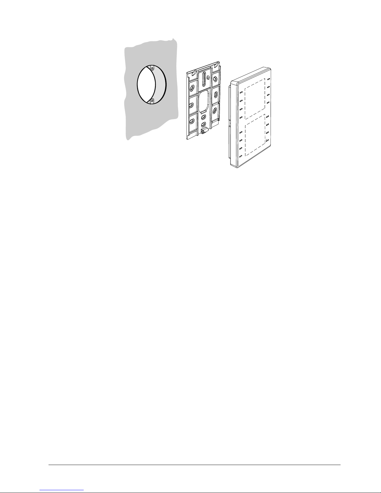
2.4 Service and connection elements
+
–
–
+
–
+
R1 QMX3... Room operator unit
N1 Controller, actor
= Twisted pair
Service LED (red)
Programming pin
The service element functions are described Commissioning, sections 6.2 and 7.2.
The devices are supplied with peel-off adhesive address labels containing the
unique KNX ID as alphanumeric and barcode display.
KNX I D 00FD00086255 Hex
AQR2570NF
The address label can peeled off the device during mounting and stuck to a floor
plan or similar. The floor plan thus contains the assignment of KNX IDs and
physical installation location. This greatly simplifies the following steps. In addition,
the procedure serves as the basis for the recommended engineering and
commissioning process. If the adhesive labels are lost, all information is still
available in printed form on the housing.
Connection
Service LED (red) and
programming pin
Adhesive address
labels
Simplifying engineerin
g
and commissioning
9 / 40
Siemens Wall-mounted sensors and room operator units for KNX S-Mode and KNX LTE-Mode CM2N1602en_01
Building Technologies Devices 2013-07-04
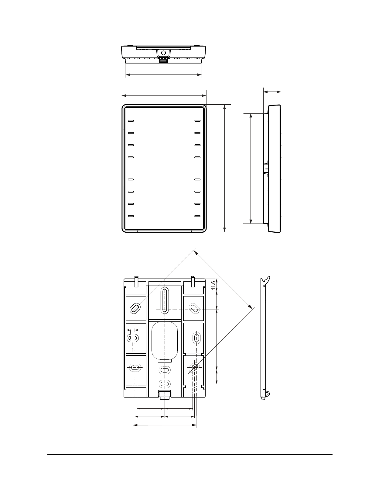
2.5 Dimensions
133.4
115
88.4
18
1602M01
_
01
80.5
7
8
.
5
60
28.2
26.5
26
13.1
56.5
17.5
28.2
3.5
1602M02
10 / 40
Siemens Wall-mounted sensors and room operator units for KNX S-Mode and KNX LTE-Mode CM2N1602en_01
Building Technologies Safety and EMC optimization 2013-07-04
2.6 Environmental compatibility, disposal
This device was developed and manufactured with environmentally compatible
materials and procedures complying with all relevant environmental standards.
Note the following to dispose of the product following its useful life or in case of
replacement:
• Do not dispose of the device as part of standard household garbage, but as
special waste from plastic and steel, ferrite-magnet components.
This applies in particular to the PCB.
• For this reason, dispose of the components compatible with current
environmental, recycling, and disposal technologies.
Observe all local, applicable laws.
• The aim is to reuse as much of the basic materials as possible at the lowest
possible environmental impact. To this end, note any material and disposal
notes in individual components.
The product environmental declaration CM2E1602
contains data on
environmentally compatible product design and assessments (RoHS compliance,
materials composition, packaging, environmental benefit, disposal)
3 Safety and EMC optimization
3.1 Notes on safety
This section explains general and system-specific regulations for mains and
operating voltages. It includes important information for your safety and the safety
of the entire plant.
Please comply with the following general regulations during engineering and
execution:
• Electrical and mains power ordinances for the given country.
• Other applicable, national regulations.
• Building installation regulations for the given country.
• Regulations of the utility company.
• Diagrams, cable lists, dispositions, specifications, and orders by the customer or
authorized engineering office.
• Third-party regulations, e.g. by the general contractor or building owner.
The electrical safety for building automation and control systems by Siemens is
essentially based on safely separating low voltage from mains voltage.
3.2 Device-specific regulations
Note permissible line lengths and topologies when planning and installing
controllers and field devices featuring KNX bus connection. Make sure the bus
supply complies with the KNX standard.
Do not open the device.
The device is maintenance free. Only the manufacturer can maintain the device.
General notes
Environmental
declaration
Please comply
with these notes
General
regulations
Safety
KNX bus supply
Warning,
maintenance

11 / 40
Siemens Wall-mounted sensors and room operator units for KNX S-Mode and KNX LTE-Mode CM2N1602en_01
Building Technologies Safety and EMC optimization 2013-07-04
3.3 Notes on EMC optimization
When setting up cable ducts, separate strongly interfering cables from susceptible
entities.
• Interfering cables: Motor cables especially from motors supplied by inverters,
energy-supplying cables.
• Susceptible entities: Control cables, low voltage cables, interface cables, LAN
cables, digital and analog signal cables.
• Both types of cables may be in the same cable duct, but in separate
compartments.
• If no three-sided, closed duct with separating wall is available, the interfering
cables must be separated by at least 150 mm from the others or placed in
separate ducts.
• Crossings of strongly interfering cables with possibly susceptible entities must
be at a right angle.
• In exceptional cases, signal and interfering power cables may be run in parallel,
resulting in a high interference risk.
We recommend to generally use unscreened cables. Comply with the
manufacturer's installation recommendations for selecting unscreened cables. In
general, unshielded twisted pair cables have sufficient EMC properties for
technical building applications (including data applications) and do not require
consideration of coupling to surrounding earth.
Setting up
cable ducts
Cable types
Separate cables
Unscreened cables
12 / 40
Siemens Wall-mounted sensors and room operator units for KNX S-Mode and KNX LTE-Mode CM2N1602en_01
Building Technologies Mounting and electrical installation 2013-07-04
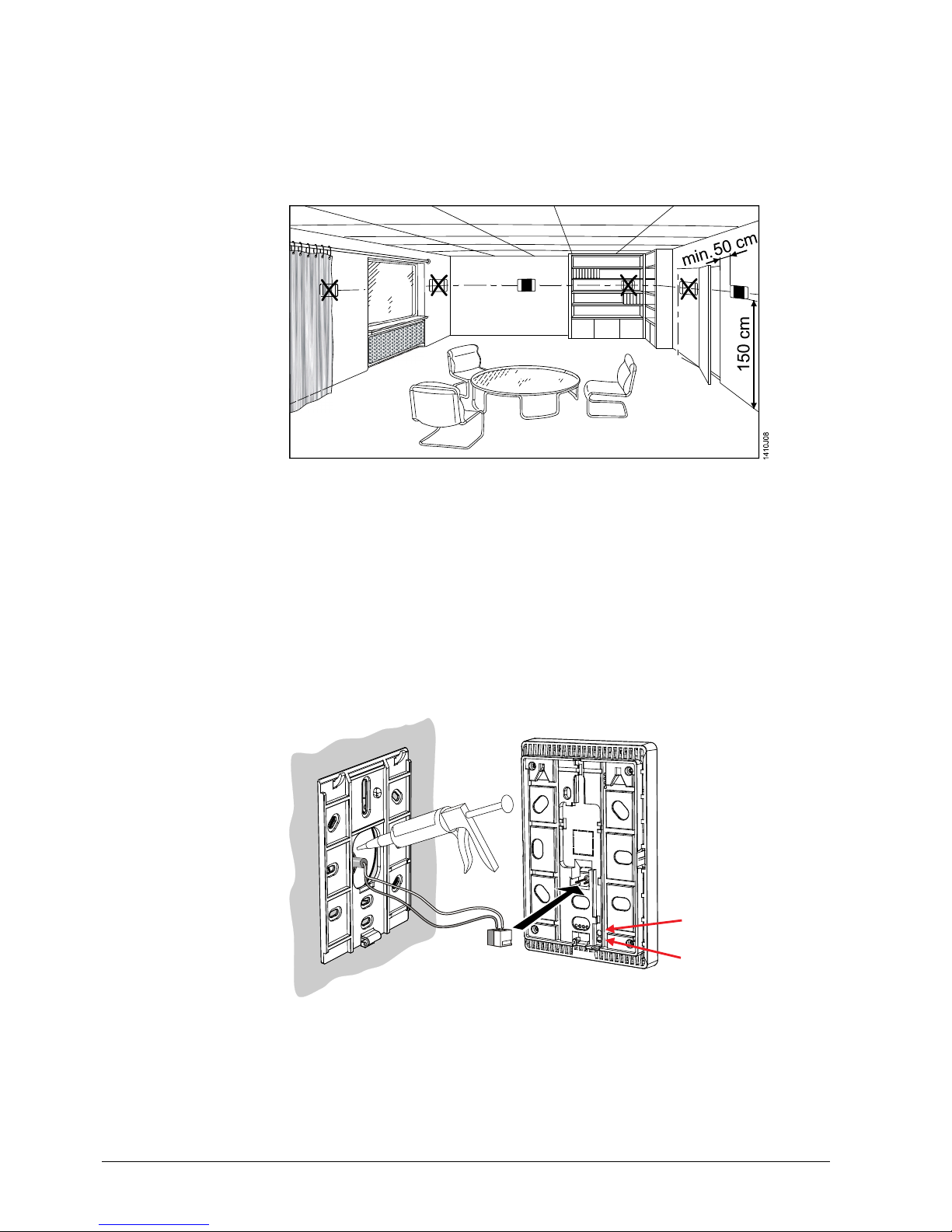
4 Mounting and electrical installation
Comply with the following notes as well as the mounting instructions [2] to mount
the room sensor.
Note the permissible ambient temperature and humidity. See data sheet [1] for
environmental conditions.
• The devices are suitable for wall mounting.
• Recommended height: 1.50 m above floor.
• Do not mount the devices in recesses, shelves, behind curtains or doors, or
above or near heat sources.
• Avoid direct solar radiation and drafts.
• Seal the conduit box or the installation tube, as air currents can affect sensor
readings.
• Adhere to allowed ambient conditions.
• Mounting instructions M1602 are enclosed with the devices.
2602J02
*
)
ServiceLED (red)
Programming pin
*) The installing tube must be sealed or cold or warm air may enter the device and
cause faulty temperature readings by the internal sensor.
Ambient conditions
Location (sensors,
room operator units)
Mounting instructions
Mounting over a
conduit box:
 Loading...