

Siemens QFM81.21, QFM81.2 Installation Instructions Manual
QFM81.2, QFM81.21 Duct Hygrostats
Product Description
These instructions explain how to install a QFM81.2
or QFM81.21 Duct Hygrostat.
Product Numbers
QFM81.2 Duct Hygrostat with external setpoint
QFM81.21 Duct Hygrostat
Required Tools
• Screwdriver
• Electric drill
• 7 mm Wrench
Expected Installation Time
15 minutes
Ensure that the air to be measured is sufficiently
mixed at the point of measurement for accurate
humidity measurements.
The mounting orientation is dependent on the air
velocity in the ductwork: at <5 m/s, the holes in the
stem must face the airflow; at >5 m/s, they must be
perpendicular to the direction of airflow. (See
Figure 2.)
Minimum Immersion Length
Installation Instructions
Document No. 129-606
July 15, 2010
<
5
m
/
s
SEN0509R1
Figure 2. Mounting Orientations.
>
5
m
/
s
Installation
Air Duct Mounting
If the duct hygrostat is used for control, mount in the
exhaust air duct after the room to be controlled.
If the duct hygrostat is used for monitoring the
maximum or minimum humidity level, mount in the
supply air duct.
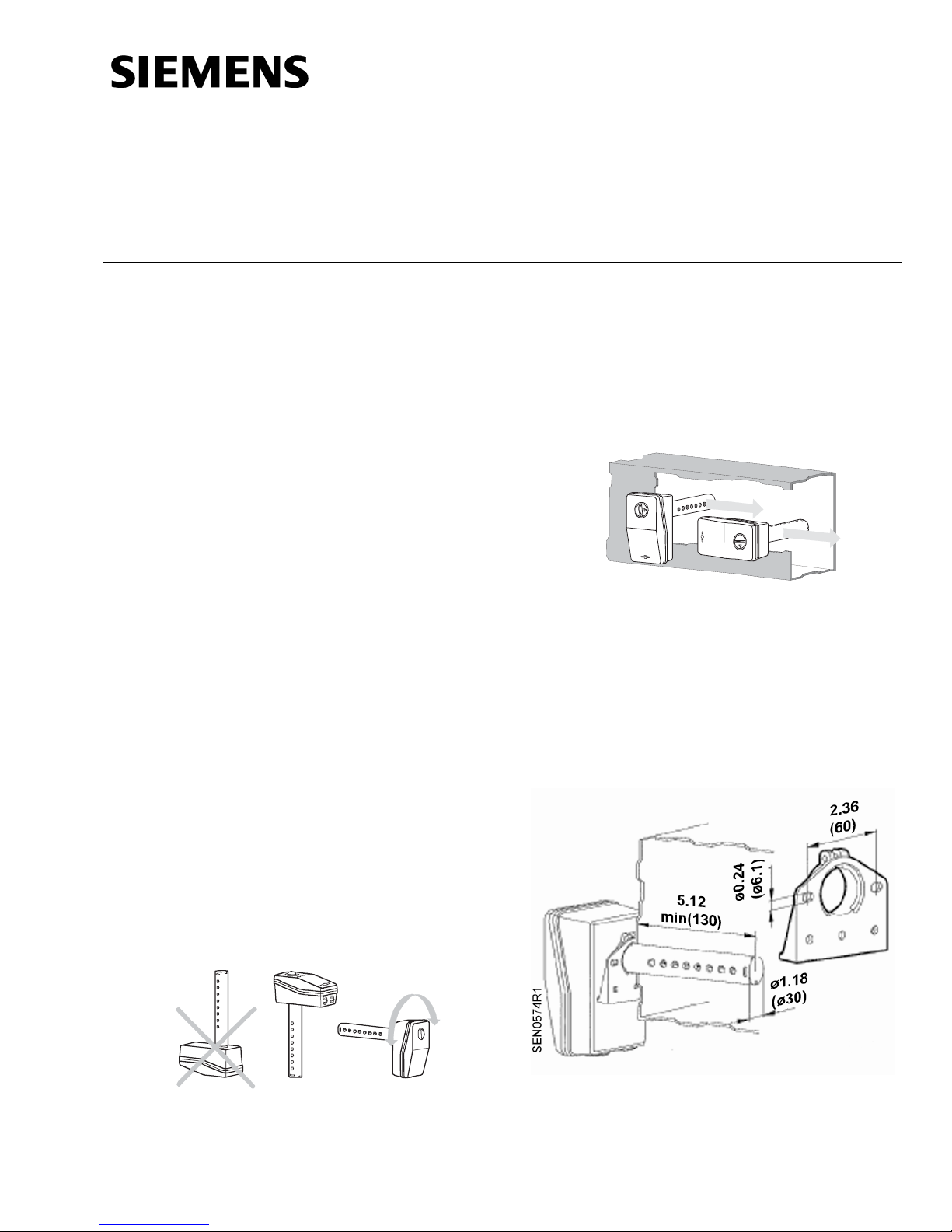
Mounting Positions
The immersion sensor stem must be mounted either
horizontally or vertically with the stem pointing
downward. Do not mount with the stem pointing
upward. (See Figure 1.)
SEN0508R1
Figure 1. Acceptable Mounting Positions.
NOTE: When mounting the hygrostat in air ducts,
the minimum immersion length of the stem
is 5.12 inches (130 mm).
The mounting flange supplied with the unit allows
the immersion length to be adjusted between
5.12 inches (130 mm) and 6.14 inches (156 mm).
Figure 3. Mounting Flange.
Item Number 129-606, Rev. AA Page 1 of 2
Document No. 129-606
Installation Instructions
July 15, 2010
Wall Mounting
The hygrostat should be mounted:
• on an inner wall approximately 4.9 feet
(1.5 m) above the floor, and at least 1.6 feet
(0.5 m) from the closest adjoining wall.
• where there is a natural circulation of room
air (do not mount near drafts, in corners,
behind curtains, too close to doors and
windows, or on an outer wall).
• away from sources of heat and refrigeration
(radiators, computers, televisions, concealed
heating pipes, hot or cold water pipes).
• where it is not exposed to direct sunlight.
NOTE: You must use the mounting flange supplied
with the hygrostat for wall mounting.
Wiring
1. Using a flat-blade screw driver, loosen the
mounting screw and remove the cover to
expose the wiring terminals.
2. Wire the device as required. See Figure 4.
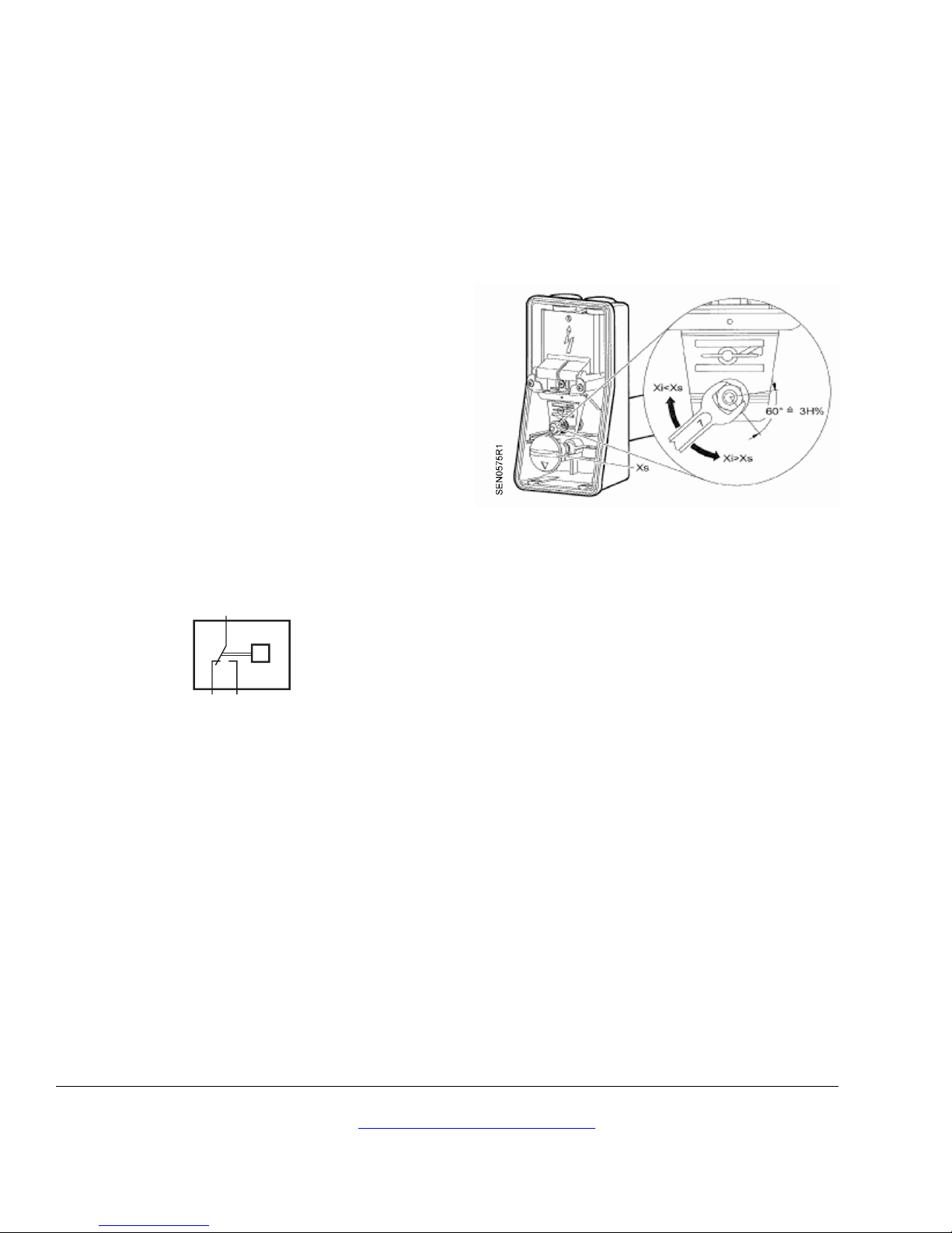
Calibration
If humidity is known and field calibration is needed,
then the device may be set to known humidity. Use
a 7 mm wrench to adjust until an audible click is
heard. This will calibrate the unit.
Figure 5. Humidity Calibration.
Replace the cover and tighten the mounting screw
with a flat-blade screwdriver.
The installation is now complete.
1
23
SEN0510R1
1 – 2 Humidification
1 – 3 Dehumidification
Figure 4. Wiring Connections.
Information in this publication is based on current specifications. The company reserves the right to make changes in specifications and
models as design improvements are introduced. Product or company names mentioned herein may be the trademarks of their respective
owners. © 2010 Siemens Industry, Inc.
Siemens Industry, Inc.
Building Technologies Division
1000 Deerfield Parkway
Buffalo Grove, IL 60089-4513
U.S.A.
Your feedback is important to us. If you have
comments about this document, please send them
to SBT_technical.editor.us.sbt@siemens.com
Document No. 129-606
Printed in the USA
Page 2 of 2
 Loading...