

Siemens QFM3100, QFM2100, QFM2101, QFM3101, QFM4101 Installation Instructions Manual
...
Installation Instructions
Q-Series Relative Humidity (RH) and
QFM2100
±5%
QFM3100
±2%
QFM2101
±5%
QFM3101
±2%
QFM4101
±2% Certified
QFM2160
±5%
QFM3160
QFM3160D
QFM4160
±2% Cert.
QFM2171
±5%
QFM3171
QFM3171D
QFM4171
±2% Cert.
QFM2110
Pt 1KΩ
QFM2120
Ni 1K
QFM3110
Pt 1K
±2%
QFM21…
155-748
QFM3160
155-749
QFM4160
155-750
Document No. 129-413
October 5, 2009
Relative Humidity & Temperature (RH/T) Duct Sensors
Product Descript ion
Relative Humidity (RH) and Relative Humidity &
Temperature (RH/T) duct sensors monitor the
relative humidity or the relative humidity and
temperature in a duct, depending on the model.
Sensors are directly wired to the controller via
twisted pair and/or three conductor cables
(18 to 22 AWG). The number and type of cables
required depends on the model selected. All field
wiring is terminated in a terminal block on the sensor
body.
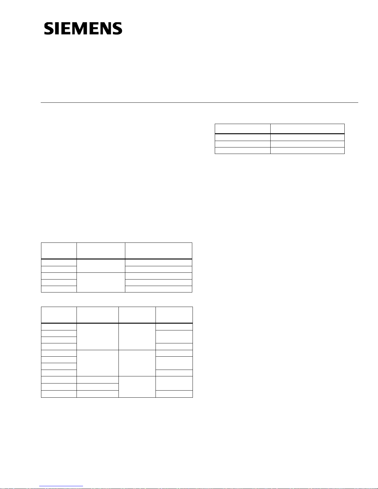
Product Numbers
Table 1. Relative Humidity Only.
Product
Number
Humidity
Signal
0 to 10 Vdc
4 to 20 mA
Accuracy
♦
Additional Reference Document s
Product Number Technical Instructions
Required Tools
• Phillips screwdrivers, No. 1 and No. 2
• Wire cutters/strippers
• Medium flat-blade screwdriver
• Tape measure
• Medium-duty electric drill
• Marker or pencil
• No. 26 (0.147-inch) drill bit
• Small level
• 7/8-inch drill bit or hole saw
• Two No. 8 × 1-inch sheet metal screws
Expected Installation Time
One hour
Table 2. Relative Humidity and Temperature.
Product
Number
♦
Applies to humidity only
Temperature
Signal
0 to 10 Vdc 0 to 10 Vdc
4 to 20 mA 4 to 20 mA
Ω
Ω
Humidity
Signal
0 to 10 Vdc
Accuracy
±2%
±2%
±5%
NOTE: Sensor tips on QFM31… and QFM41…
models are field replaceable.
Item Number 129-413, Rev. CA Page 1 of 3
Prerequisites
♦
• Ensure that the appropriate field wiring is
installed.
Appropriate wiring is one or more twisted
pairs, or three conductor cables (plenum or
non-plenum as required), within the maximum
wiring run length for the individual equipment
controller. The maximum recommended
length is 750 feet (229 m).
• Ensure that all wiring complies with National
Electric Code (NEC) and local regulations.
Mounting Infor m a t ion
Locate the sensor:
• In the center of a duct.
• Away from fans, corners, heating and cooling
coils, and so on.
• Where it receives adequate airflow for proper
operation.
Document No. 129-413
Installation Instructions
October 5, 2009
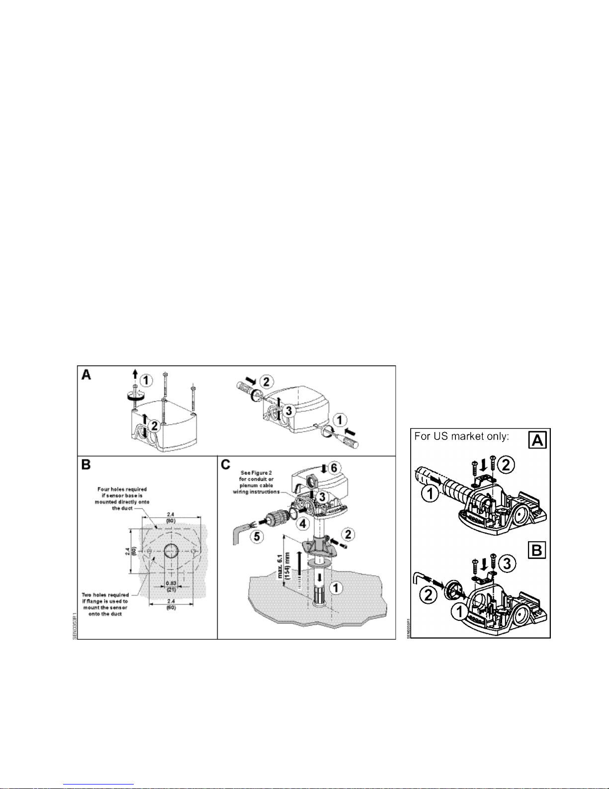
Instructions
1. Drill a 7/8-inch diameter hole into the duct at the
desired location of the sensor.
2. Decide if the sensor will be mounted directly to
the duct or if the mounting flange will be used.
• Sensor Mounting Bracket Installation
a. Use the bracket as a template, and drill
two holes with a No. 26 (0.147-inch) drill
bit. See Figure 1(B).
b. Attach the sensor mounting bracket and
gasket to the duct using two No. 8 × 1inch sheet metal screws. See
Figure 1(C1).
c. Insert the sensor in the duct through the
bracket and tighten the mounting screw
to set the insertion depth. See
Figure 1(C2).
• Direct installation:
a. Remove the sensor cover.
b. Use the base as a template, and drill four
holes with a No. 26 (0.147-inch) drill bit.
See Figure 1(B).
c. Insert the probe through the gasket and
into the hole. Secure the head to the duct
with four No. 8 × 1-inch sheet metal
screws.
3. Attach conduit or plenum wire to the sensor
base. See Figures 1 and 2.
4. If you are using conduit, pull the field wiring
through the conduit and into the sensor base.
5. Connect the field wiring to the sensor terminal
block on the base. See Figures 3 through 7 for
wiring diagrams.
6. Reinstall the sensor cover. See Figure 1(C6).
The installation is now complete.
Figure 1. RH/T Duct Sensor Installation. Figure 2. Conduit or Plenum
Cable Wiring Installation.
NOTE: Figure 2 shows how to connect the conduit or plenum cable to the sensor head.
.
Page 2 of 3 Siemens Industry, Inc.
 Loading...