

Siemens QFA3100, QFA3101, QFA3160, QFA3160D, QFA3171 Installation Instructions Manual
...
Installation Instructions
Q-Series Outdoor Air Relative Humidity
Sensors
QFA3100
Outdoor air humidity sensor (2%),
0 to 10 Vdc
QFA3101
Outdoor air humidity sensor (2%),
4 to 20 mA
QFA3160
Outdoor air humidity sensor (2%),
0 to 10 Vdc/Temp 0 to 10 Vdc
QFA3160D
Outdoor air humidity sensor (2%),
display
QFA3171
Outdoor air humidity sensor (2%),
4 to 20 mA/Temp 4 to 20 mA
QFA3171D
Outdoor air humidity sensor (2%),
display
QFA4171
Outdoor air humidity sensor (2%),
4 to 20 mA/Temp 4 to 20 mA, certified
QFA4171D
Outdoor air humidity sensor (2%),
with displa y
QFA4160
Outdoor air humidity sensor (2%),
0 t 10 Vdc/Temp 0 to 10 Vdc, certified
QFA4160D
Outdoor air humidity sensor (2%),
with displa y
Accessories
AQF3101
Sensor filter cap
AQF4150
Replaceable, certified sensor tip
AQF3100
Sun shield
74 662 0104 0
US 1/2-inch rigid conduit adapter
Document No. 129-416
October 5, 2009
and Relative Humidity & Temperature
Product Description
The Q-Series Outdoor Air Relative Humidity, and
Relative Humidity & Temperature Sensors monitor
and transmit changes in humidity and temperature to
the building control systems. These units are
especially suited for applications where precise,
stable humidity sensing is required. Standard
models available are 2% and 2% certified, for both
humidity only and combination humidity with
temperature sensing. Sensors are offered with either
4 to 20 mA or 0 to 10 Volt output signals.
Product Numbers
Part Number Description
0 to 10 Vdc/Temp 0 to 10 Vdc with
4 to 20 mA/Temp 4 to 20 mA with
Required Tools
Expected Installation Time
30 minutes
Prerequisites
• Ensure that the appropriate field wiri ng is
• Ensure that all wiring complies with National
Installation
• Phillips screwdrivers, sizes No. 1 and No. 2
• Medium flat-blade screwdriver
• Wire cutters/strippers
• Tape measure
• Medium-duty electric drill
• Drill bit for wall anchor hole
• Marker or pencil
• Two No. 10 screws and wall anchors
installed.
Appropriate wiring is one or more twisted pair or
three conductor cables (plenum or non-plenum
as required) within the maximum wiring run
length for the humidity/temperature controller.
The maximum recommended length is 750 feet
(229 m).
Electric Code (NEC) and local regulations.
4 to 20 mA/Temp 4 to 20 mA, certified
0 t 10 Vdc/Temp 0 to 10 Vdc, certified
Item Number 129-416, Rev. BA Page 1 of 2
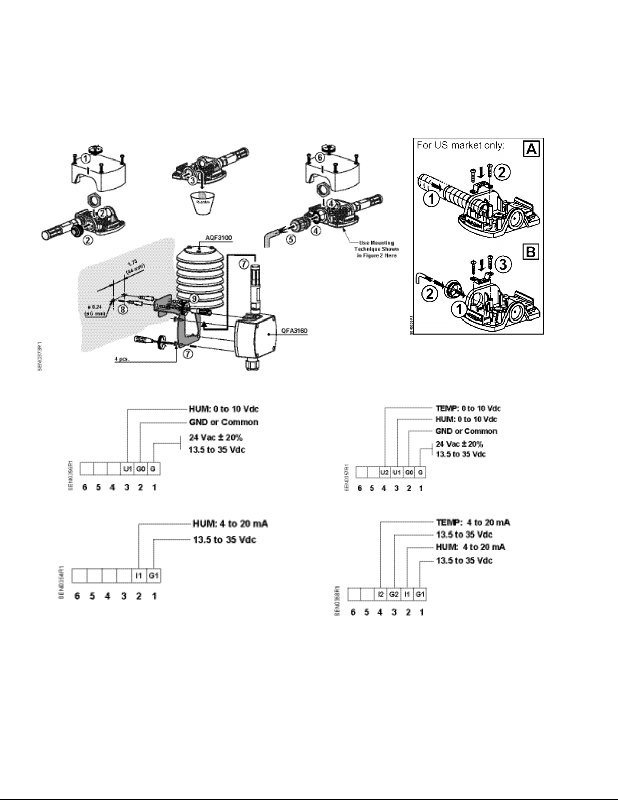
1. Determine where the sensor is to be located and
install the Sun Shield, AQF3100, as shown in
Figure 1. The installation surface determines
which mounting components are to be used.
NOTE: The shield must be mounted vertically
as shown in Figure 1.
2. Remove sensor cover and install plug in
knockout next to sensing probe. See
Figure 1 (2).
3. Pull the field wiring through the conduit and into
the sensor base. See Figure 2.
Document No. 129-416
Siemens Indus try, Inc.
+ 1 847-215-1000
Your feedback is important to us. If you have comments
Document No. 129-416
QFA3100
QFA3160/QFA4160
Figure 3. Wiring Diagrams for RH Sensors.
Installation Instructions
October 5, 2009
4. Connect the field wiring to the sensor terminal
block on the base. See Figures 3 and 4 for
wiring diagrams.
Figure 1. Rh/T Outdoor Air Sensor Installation.
5. Install the sensor onto the Shield as shown. See
Figure 1 (7).
The installation is now complete.
Figure 2. Field Wiring.
QFA3101
Information in this publication is based on current specifications. The company reserves the right to make changes in specifications and
models as design improvements are introduced. Product or company names mentioned herein may be the trademarks of their respective
owners. © 2009 Siemens Industry, Inc.
Building Technologies Division
1000 Deerfield Parkway
Buffalo Grove, IL 60089
Figure 4. Wiring Diagrams for RH/T Sensors.
about this document, please send them to
SBT_technical.editor.us.sbt@siemens.com
QFA3171/QFA4171
Printed in the USA
Page 2 of 2
 Loading...