

Siemens QPA228.FWNC Series, QPA228.FWSC Series, QAA2280.FWNC, QAA2280.FWSC, QFA3280.FWNC Operator Interface Manual
...
Operator Interface Guide
Room Unit for TEC, and ATEC
Overview
This document explains the set up and operation of the
Series 2200, and 3200 room unit s. It explains the
various operating modes available and describes the
procedure f or programming the display, according to
user preferences.
These devices are used with BACnet Terminal
Equipment Controllers (TEC), BACnet Actuat or TEC
(ATEC) Controll ers, and BACnet Programmable
Controllers (PTEC).
Product Numbers
Docume nt No. 125- 703
September 19, 2017
QAA2280.FWNC QPA228x.FWSC
QAA2280.FWSC QFA3280.FWNC
QPA228x.FWNC QFA3280.FWSC
Accessories
Description Product Number
Passkey 544-643A
25-foot (7.6 m) cable with
connections
50-foot (15.2 m) cable with
connections
100-foot (30.5 m) cable with
connections
Replacement Relative
Humidity Sensing Element
for QFA and QP A
Replacement Housing Base
(QAA, QF A types)
Replacement Housing Base
(QPA types)
Room Unit Backplate,
10-pack
Power Supply (QPA types)
Wall Gasket, 10-pack
588-100A
588-100B
588-100C
AQF3060
563-102-01
563-120
AQM2200-INTL
AQM2200
563-102 GSKT KIT
Operation
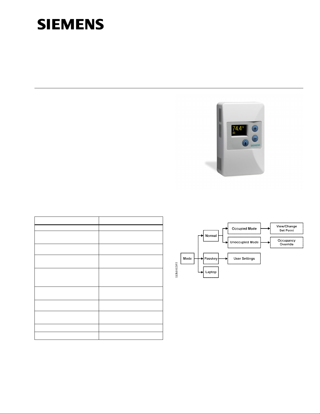
Operation modes
Figure 1. Operation Modes.
Normal Mode
In Normal Mode, the displ ay is updated with
temperature, humi dity, carbon dioxide, and/or occ upied
status (all where appl icable) on a set time cycle.
The display shows tem perature in the desired units (as
set by the cli pable j umper on the PCA). Depending on
the model, the humidity and/or carbon dioxide value(s)
will be displayed as well. When multiple variables need
to be displayed (temperature, relative humidity, and/or
carbon dioxide) the display will cycle through the
required values at a rate of one change every three to
five seconds.
Page 1 of 4
Document No. 125-703
Operator Interface Guide
September 19, 2017
Operation modes, Continued
Occupied Mode
If the TEC is currently in Unoccupied Mode (display
shows man outside of the house), pressing the
override button (button designated by an image of a
man inside a house) results in the display showing the
word OCCUPIED and the request is sent to the TEC to
override the unoccupied mode. If the TEC does not get
overridden, and stays in unoccupied mode, the display
on the sensor reverts back to the unoccupied symbol
as soon as possible.
If the TEC is currently in occupied mode, pressing the
override button flashes the word OCCUPIED, and does
nothing else. This functionality is intended solely to let
the user know that the butt on press was recognized.
Occupied Mode Unoccupied Mode
Display Display
Setpoint Adjustment Mode
The temperature setpoint is adjusted by using the plus
and minus buttons. The resulting changes in setpoint
are displayed on t he di spl ay in 1.0°F or 0.5°C
increments.
The setpoint adjustment will display for three seconds.
If, during those three seconds, a setpoint button is
pressed again, the setpoint will be adjusted accordingly
and be displayed, and t he three- second count down will
restart. If there is no user input for more than three
seconds, the room unit will return to Normal Mode.
• Press the plus/minus buttons t o scroll through the
various options available for each parameter to
display the desired option.
• Press the occupancy override button again to
move to the next user adjustable parameter.
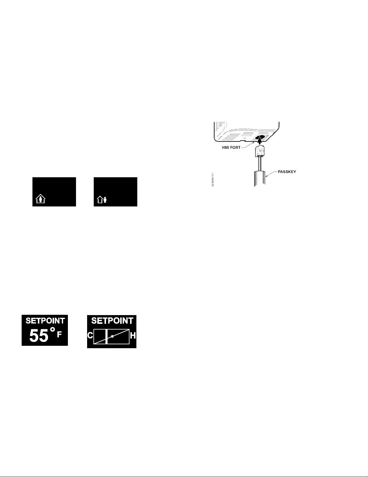
• When fi nished, remove the passkey f rom t he HMI
port. User setti ng changes will be saved when the
passkey is removed.
Figure 2. Inserting the Passkey.
NOTE: When the passkey is plugged i n,
communication between the room unit and the
TEC is disabled. See note in Laptop Pass-thru
Mode section for more information.
Settings
• Set Pt Disp - determines how the user views the
temperature setpoint adjustment. The default setting
is NUMERIC, and displ ays in degrees. The user can
select between a NUMERIC and a GRAPHIC
setpoint displ ay.
• Set Pt Min - determines the minimum temperature
setpoint value. The default setting is 55°F (12.5°C).
The user selects the minimum setpoint the room unit
should request. The setpoint limit is ultimately
defined in the controller. If the setpoint is displayed
graphically as a sliding bar, this sets the left end of
the slider bar. The limits are 55°F to the Set Pt Max
value. The adj ustm ent step size is 1°F (0.5°C).
Passkey Mode
Insert the passkey in the sensor HMI (Human-Machine
Interface) port to setup all of the user functionality listed
below. For each parameter, use the following
sequence:
• Press the occupancy override button to edit the
parameter.
Page 2 of 4 Siemens Industry, Inc.
• Set Pt Max - determines the maximum temperature
setpoint value. The default setting is 95°F (35°C).
The user selects the max imum setpoint the sensor
should request. The setpoint limit is ultimately
defined in the controller. If the setpoint is displayed
graphically as a sliding bar, this sets the right end of
the slider bar. The limits are Set Pt Min to 95°F
(35°C). The adjustment step size is 1°F (0.5°C).
 Loading...