

Siemens QFA3212.FWxN, QFA32SS.FWxN, FA3212.EWxN, QFA32SS.EWxN, FA3232.EWxN Installation Instructions Manual
Installation Instructions
Series
2200 and 3200 Relative
Humidity
and Temperature Room Units
CAUTION
Docume nt No. 129-104
Decemb er 11, 2017
Product Description
These room units measure relative humidity and
temperature in the occupied space in which they are
install ed. Models wit h display allow users to view the
measured temperature value. A version with
temperature setpoint adjustment is also off ered.
The effective sensing range is 32°F to 122°F (0°C to
50°C), and the setpoi nt range is 55°F to 95°F (13°C
to 35°C). The humidity measuring range is 0 to
100% RH.
Hardware is included for installation on drywall or on
a 2” × 4” electrical box.
Product Numbers
QFA3212.FWxN QFA32SS.FWxN
QFA3212.EWxN QFA32SS.EWxN
QFA3232.EWxN
Accessories
AQA2200-INTL Room Unit Back Plate
(10-pack)
563-102 GSKT KIT Room Sensor Insulating
Gasket (10-pack)
(For hollow wall installations)
Expected Installation Time
20 minutes
Required Tools
• Sizes 1 and 2 Phillips screwdrivers
• Small and medium flat-blade screwdrivers
• 1/16-inch hex key
• Medium-duty electric drill
• 3/16-inch (4.8 mm) drill bit
• One-inch (25 mm) hole saw
• Small level
• Tape measure
• Marker or pencil
Prerequisites
• Review these instructions before beginning.
• Installed: appropriate field wiring within the
maximum wiring run length for the individual
equipment controller. The maximum
recommended length is 750 feet (229 m) for
18 AWG; 300 feet (91 m) for 22 AWG.
• All wiring must comply with National Electric
Code (NEC) and local regulations.
Caution Notations
Equipm ent damage or l oss of
data may occur if you do not
follow a procedure as
specified.
Item Number 129-104, Rev. JA
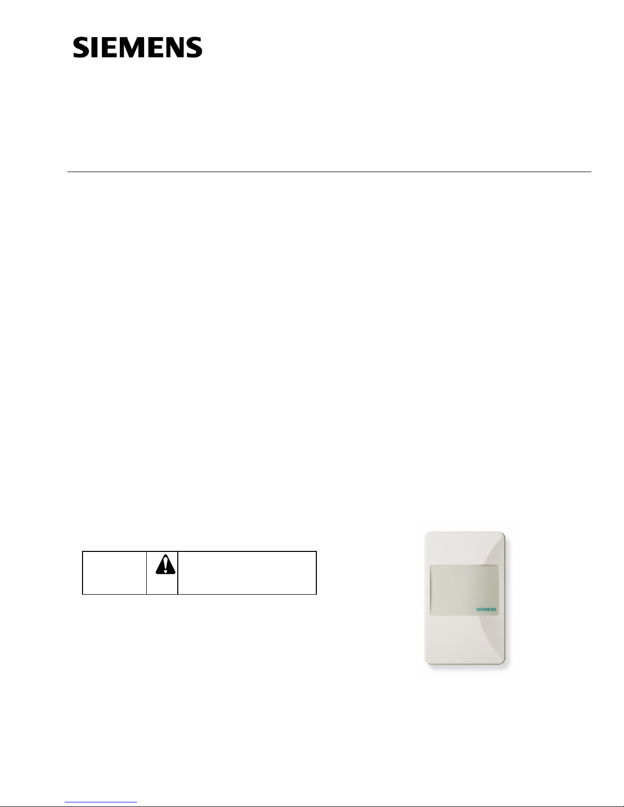
Figure 1. Typical Temperature Room Unit.
Page 1 of 4
Document No. 129-104
Installation Instructions
December 11, 2017
Mounting Information
Always mount the room unit vertically.
Locate the room unit:
• according to design specifications and local
regulations.
• where the air circulates around it freely (not in
recessed areas or behind doors).
• allowing a minimum of 4 inches (10 cm) free
space above and below for proper airflow, the
front cover removal tool, and the computer
communicati on cabl e.
• away from drafts caused by doors, windows,
outside walls, air registers, pipes, return air
plenums, etc.
• away from heat sources such as strong lights,
fireplaces, direct sunlight, etc.
• on an inside wall (preferably), about 5 feet
(1.5 m) above the finished floor, or per code
(ANSI, ADA, or local regulation).
Drywall Mounting (No Rough-in),
Typical
Base Plate Mounting and Wiring
1. Mark the center (cable) hole and the mounting hole
locations, using t he room unit base plate as a
template. See Figure 3.
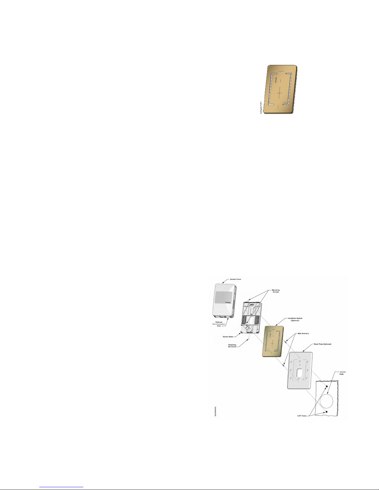
Figure 2. Insulating Gasket.
4. Pull about three inches (75 mm) of the cable through
the hole in the base plate.
5. Mount the room unit base plate on the wall, noting
the UP arrow:
NOTE: If required, position the back plate behind
the room unit base, aligning the top and
bottom mounting holes, prior to mounting
to the wall:
a. Install the two mounting screws prov ided, but
do not tighten.
b. Level the room unit base plate for appearance.
c. Ti ghten the two mounting screws to the room
unit base plate.
6. Cut the cable, leaving about three inches (75 mm)
on the room unit side of the drywall. Ensure that pin
Number 1 connects to the same wire at each end of
the cable.
2. Drill two 3/16-inch (4.8 mm) mounting holes and
mount the two plastic wall anchors flush to below the
wall surface for stable mounting of the device.
3. Cut a 1-inch (25 mm) center hole with a hole saw.
NOTE: It is recommended that you use the
optional Insulating Gasket* on the back
of the Unit Base for hollow wall
install ati ons.
When applying the adhesive-backed
gasket to the back of the unit base, orient
the gasket so that the cut-out arrow
portion of the gasket is in the upper
lefthand quadrant of the unit base. The
sensor base has an UP arrow mol ded
into the surf ace in the same quadrant
location (see Figure 6).
*Insulating gasket s are sold in 10-packs
(Part Number 563-102 GSKT KIT).
Page 2 of 4 Siemens Industry, Inc.
NOTE: See Figure 2 for details on optional Gasket
application.
Figure 3. Drywall Mounting (No Rough-in), Typical.
 Loading...