

Siemens QFA2000, QFA2020, QFA2040, QFA2060 User Manual

CE1N1857en
06.06.2005
Siemens Building Technologies
HVAC Products
1
857
Room Sensors
QFA20…
for relative humidity and temperature
• Operating voltage AC 24 V or DC 13.5…35 V
• Signal output DC 0...10 V for relative humidity
• Signal output DC 0...10 V or LG-Ni 1000 or T1 for temperature
• Accuracy of ± 3 % r.h. within comfort range
• Range of use −15…+50 °C / 0…95 % r. h. (non-condensing)
Use
In ventilating and air conditioning plants to acquire
• relative humidity and
• temperature
in rooms.
The QFA20… is used as a
• control sensor and
• measuring sensor for building automation and control systems or indicating units.
Type summary
Type
reference
Temperature
measuring range
Temperature
signal output
Humidity
measuring range
Humidity
signal output
Operating voltage
QFA2000 None None 0...100 % Active, DC 0...10 V AC 24 V or DC 13.5…35 V
QFA2020 0...50 °C Passive, LG-Ni 1000 0...100 % Active, DC 0...10 V AC 24 V or DC 13.5…35 V
QFA2040 0...50 °C Passive, T1 0...100 % Active, DC 0...10 V AC 24 V or DC 13.5…35 V
QFA2060 0...50 °C / − 35...+ 35 °C Active, DC 0...10 V 0...100 % Active, DC 0...10 V AC 24 V or DC 13.5…35 V
.
.
.
.
1857P01
2/6
Siemens Building Technologies Room sensors QFA20… CE1N1857en
HVAC Products 06.06.2005
Ordering
When ordering, please give name and type reference.
Equipment combinations
All systems or devices capable of acquiring and handling the sensor’s DC 0...10 V,
LG-Ni 1000 or T1 output signal.
When using the passive sensors for averaging, we recommend to use the SEZ220
signal converter (refer to Data Sheet N5146).
Mode of operation
The sensor acquires the relative humidity in the room via its capacitive humidity sensing element whose electrical capacitance changes as a function of the relative humidity.
The electronic measuring circuit converts the sensor’s signal to a continuous
DC 0...10 V signal, which corresponds to 0...100 % relative humidity.
The sensor acquires the temperature in the room via its sensing element whose electrical resistance changes as a function of the temperature.
Depending on the type of sensor, this change in resistance is converted either to an
active DC 0…10 V output signal (
0… 50 °C or –35…+35 °C) or is provided as a
simulated passive LG-Ni 1000 or T1 output signal.
The measuring current from systems/devices für acquiring the electrical resistance of
the passive sensor differs greatly and impacts self-heating of the temperature sensing
element at the end of the measuring probe. To compensate the impact, the passive
output signal is simulated with an electronic circuit.
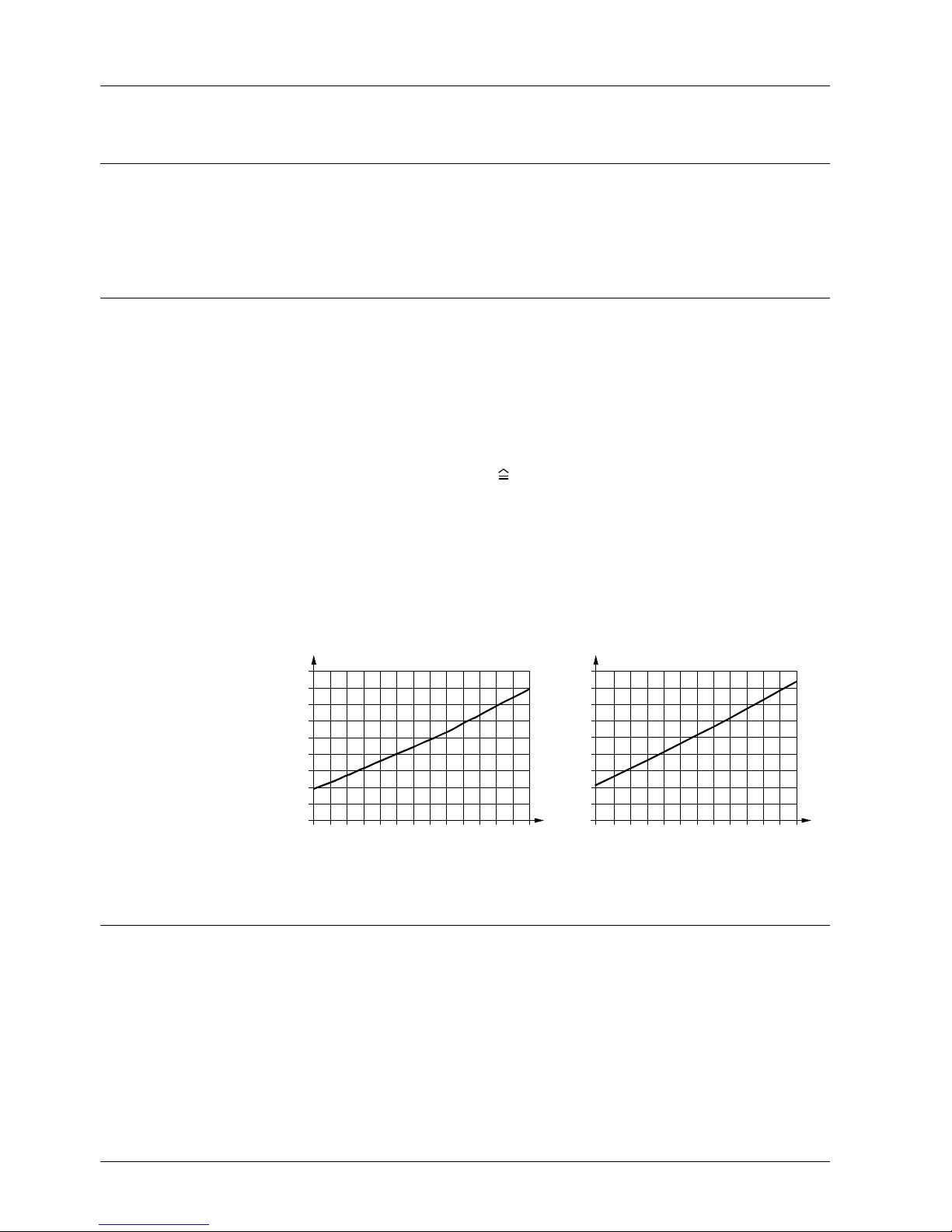
Characteristic LG-Ni 1000 Characteristic T1 (PTC)
−40−30−20−
10 0 1020304050607080
1400
1200
1000
800
600
R
[Ω]
[°C]
1811D01
−
50
ϑ
−40−30−20−
10 0 10 20 30 40 50 60 70 80
3000
2600
2200
1800
1400
R
[Ω]
[°C]
1864D01
ϑ
1600
2000
2400
2800
3200
R Resistance value in Ohm
ϑ Temperature in degrees Celsius
Mechanical design
The units have been designed for wall mounting. They are suitable for use with most
commercially available recessed conduit boxes. The cables can be introduced from the
rear (concealed wiring) or from below or above (surface-run wires) through knock-out
openings.
The units consist of two major sections: Casing and baseplate. Both snap together but
can be detached again.
The measuring circuit, the sensing elements and the setting element are located on the
printed circuit board inside the casing.
The baseplate carries the connecting terminals.
Relative humidity
Temperature
.
.
.
.
.
.
.
.
Simulated passive
output signal
Sensing elements,
simulated
Legend
 Loading...