

Page 1
CE1N1857en
06.06.2005
Siemens Building Technologies
HVAC Products
1
857
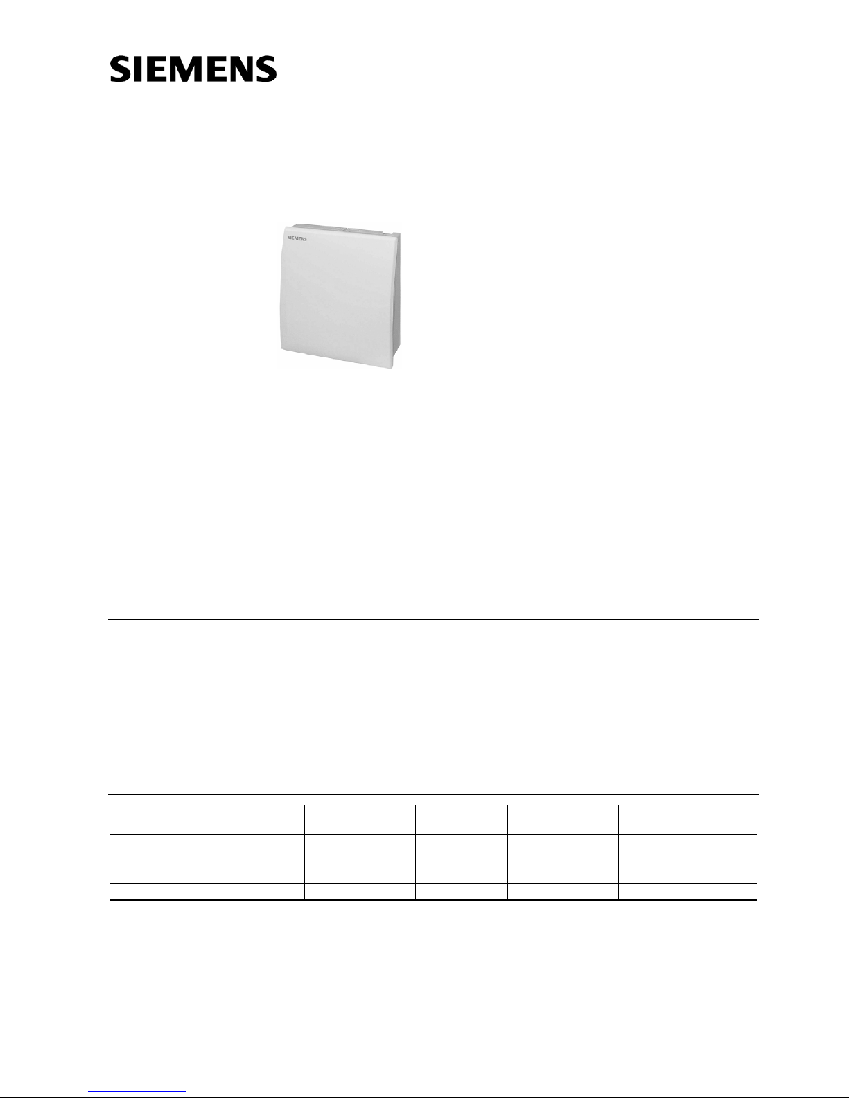
Room Sensors
QFA20…
for relative humidity and temperature
• Operating voltage AC 24 V or DC 13.5…35 V
• Signal output DC 0...10 V for relative humidity
• Signal output DC 0...10 V or LG-Ni 1000 or T1 for temperature
• Accuracy of ± 3 % r.h. within comfort range
• Range of use −15…+50 °C / 0…95 % r. h. (non-condensing)
Use
In ventilating and air conditioning plants to acquire
• relative humidity and
• temperature
in rooms.
The QFA20… is used as a
• control sensor and
• measuring sensor for building automation and control systems or indicating units.
Type summary
Type
reference
Temperature
measuring range
Temperature
signal output
Humidity
measuring range
Humidity
signal output
Operating voltage
QFA2000 None None 0...100 % Active, DC 0...10 V AC 24 V or DC 13.5…35 V
QFA2020 0...50 °C Passive, LG-Ni 1000 0...100 % Active, DC 0...10 V AC 24 V or DC 13.5…35 V
QFA2040 0...50 °C Passive, T1 0...100 % Active, DC 0...10 V AC 24 V or DC 13.5…35 V
QFA2060 0...50 °C / − 35...+ 35 °C Active, DC 0...10 V 0...100 % Active, DC 0...10 V AC 24 V or DC 13.5…35 V
.
.
.
.
1857P01
Page 2
2/6
Siemens Building Technologies Room sensors QFA20… CE1N1857en
HVAC Products 06.06.2005
Ordering
When ordering, please give name and type reference.
Equipment combinations
All systems or devices capable of acquiring and handling the sensor’s DC 0...10 V,
LG-Ni 1000 or T1 output signal.
When using the passive sensors for averaging, we recommend to use the SEZ220
signal converter (refer to Data Sheet N5146).
Mode of operation
The sensor acquires the relative humidity in the room via its capacitive humidity sensing element whose electrical capacitance changes as a function of the relative humidity.
The electronic measuring circuit converts the sensor’s signal to a continuous
DC 0...10 V signal, which corresponds to 0...100 % relative humidity.
The sensor acquires the temperature in the room via its sensing element whose electrical resistance changes as a function of the temperature.
Depending on the type of sensor, this change in resistance is converted either to an
active DC 0…10 V output signal (
0… 50 °C or –35…+35 °C) or is provided as a
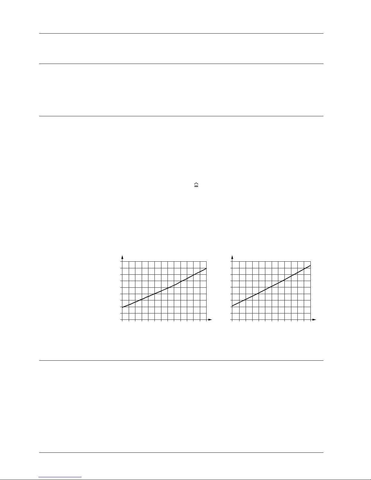
simulated passive LG-Ni 1000 or T1 output signal.
The measuring current from systems/devices für acquiring the electrical resistance of
the passive sensor differs greatly and impacts self-heating of the temperature sensing
element at the end of the measuring probe. To compensate the impact, the passive
output signal is simulated with an electronic circuit.
Characteristic LG-Ni 1000 Characteristic T1 (PTC)
−40−30−20−
10 0 1020304050607080
1400
1200
1000
800
600
R
[Ω]
[°C]
1811D01
−
50
ϑ
−40−30−20−
10 0 10 20 30 40 50 60 70 80
3000
2600
2200
1800
1400
R
[Ω]
[°C]
1864D01
ϑ
1600
2000
2400
2800
3200
R Resistance value in Ohm
ϑ Temperature in degrees Celsius
Mechanical design
The units have been designed for wall mounting. They are suitable for use with most
commercially available recessed conduit boxes. The cables can be introduced from the
rear (concealed wiring) or from below or above (surface-run wires) through knock-out
openings.
The units consist of two major sections: Casing and baseplate. Both snap together but
can be detached again.
The measuring circuit, the sensing elements and the setting element are located on the
printed circuit board inside the casing.
The baseplate carries the connecting terminals.
Relative humidity
Temperature
.
.
.
.
.
.
.
.
Simulated passive
output signal
Sensing elements,
simulated
Legend
Page 3
3/6
Siemens Building Technologies Room sensors QFA20… CE1N1857en
HVAC Products 06.06.2005
R1
0 V
5 V
10 V
5 V
5 V
0 V
5 V
10 V
U1 U2 BS-MS
75 °C
35 °C
20 °C
R1
R2
R3
R2
R3
20 °C
Measuring range
Test function active
1857Z01en
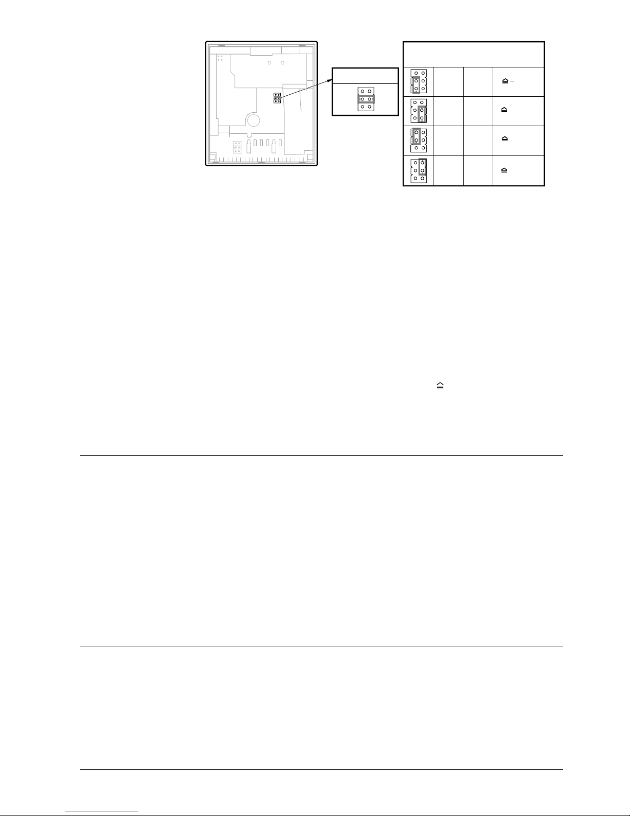
The setting element is accessible after removing the baseplate. It consists of 6 pins and
a shorting plug. It is used to select the required measuring range and to activate the
test function.
The different plug positions have the following meaning
• For the passive temperature measuring range:
Shorting plug in the mid position (R2) = LG-Ni 1000 or T1
• For the activating temperature measuring range:
Shorting plug in the upper position (R1) = − 35...+ 35 °C,
Shorting plug in the mid position (R2) = 0...50 °C (factory setting),
Shorting plug in the lower position (R3) = 0...50 °C
• For activating the test function:
Shorting plug in the vertical position: The values according to the table "Test function
active" will be made available at the signal output.
• Should the temperature sensor become faulty, there will be after 60 seconds a voltage of 0 V at signal output U2 or signal output BS-MS
− 35 °C, and the humidity
signal at signal output U1 will reach 10 V
• Should the humidity sensor become faulty, there will be a voltage of 10 V at signal
output U1 after 60 seconds, and the temperature signal will remain active
Engineering notes
To power the sensor, a transformer for safety extra low-voltage (SELV) with separate
windings for 100 % duty is required. When sizing and protecting the transformer, the
local safety regulations must be observed.
When sizing the transformer, the power consumption of the room sensor must be taken
into consideration.
For correct wiring of the sensor, refer to the Data Sheets of the devices with which the
sensor is used.
The permissible line lengths must be observed.
When laying the cables, it must be observed that the longer the cables run side by side
and the smaller the distance between them, the greater the electrical interference.
Shielded cables must be used in environments with EMC problems.
Twisted pair cables are required for the secondary supply lines and the signal lines.
Fitting notes
On an inner wall of the space to be air conditioned. Not in recesseds, shelves, not behind curtains, not opposite or near heat sources.
The unit must not be exposed to spot lights or direct solar radiation.
The end of the conduit at the sensor must be sealed to prevent false measurements
due to draughts through the conduit.
Installation instructions are printed on the packing.
Setting element
Fault
Cable routing and
cable selection
Location
Installation instructions
Page 4

4/6
Siemens Building Technologies Room sensors QFA20… CE1N1857en
HVAC Products 06.06.2005
Commissioning notes
Check wiring before switching on power. The temperature measuring range must be
selected on the sensor, if required.
Wiring and the output signals can be checked by making use of the test function (refer
to "Mechanical design").
We recommend not to use voltmeters or ohmmeters directly at the sensing element. In
the case of the simulated passive output signals, measurements with commercially
available metres cannot be made (measuring current too small).
Technical data
Operating voltage AC 24 V ± 20 % or DC 13.5...35 V
Frequency 50/60 Hz at AC 24 V
Power consumption ≤ 1 VA
Perm. cable lengths refer to Data Sheet of the device
handling the signal
Range of use 0…95 % r. h. (non-condensing)
Measuring range 0…100 % r. h.
Measuring accuracy at 23 °C and AC 24 V
0...95 % r.h.
30...70 % r.h.
± 5 %
± 3 %, typically
Temperature dependency ≤ 0.1 % r. h./°C
Time constant 2 min
Perm. air velocity 20 m/s
Output signal, linear (terminal U1) DC 0...10 V 0...100 % r. h.,
max. ± 1 mA
Range of use − 15...+50 °C
Measuring range 0...50 °C / − 35...+ 35 °C
Sensing element NTC 10 kΩ
Measuring accuracy at
15...35 °C
− 35...+50 °C
± 0.8 K
± 1 K
Time constant 8 min (depending on air movement
and thermal coupling to the wall)
Output signal, linear (terminal U2) DC 0...10 V 0...50 °C / − 35...+ 35 °C
max. ± 1 mA
Measuring range 0...50 °C
Sensing element simulated, corresponding to
QFA2020
QFA2040 (serie B or higher)
LG-Ni 1000
T1 (PTC)
Measuring accuracy at
15...35 °C
− 35...+50 °C
± 0.8 K
± 1 K
Time constant 8 min (depending on air movement
and thermal coupling to the wall)
Perm. measuring current with
QFA2020
QFA2040
1.18…3.29 mA
0.53…1.46 mA
Housing IP 30 to IEC 529
Safety class III to EN 60 730
Screw terminals for 1 × 2.5 mm2 oder 2 × 1.5 mm2
.
.
.
.
.
.
.
Power supply
Cable lengths for
measuring signal
…
…
…
.
.
Functional data of
humidity sensor
…
…
.
.
.
Functional data of
temperature sensor with
QFA2060
Functional data of
temperature sensor with
QFA2020, QFA2040
…
.
.
.
…
…
…
.
.
Degree of protection
Electrical connections
Page 5

5/6
Siemens Building Technologies Room sensors QFA20… CE1N1857en
HVAC Products 06.06.2005
Operation to
Climatic conditions
Temperature (housing with electronics)
Humidity
Mechanical conditions
IEC 721-3-3
class 3K5
− 15...+50 °C
0…95 % r. h (non-condensing)
class 3M2
Transport to
Climatic condition
Temperature
Humidity
Mechanical conditions
IEC 721-3-2
class 2K3
− 25...+ 70 °C
<95 % r. h.
class 2M2
Housing front ASA + PC, NCS S 0502-G (white)
Bottom section of housing ASA + PC, NCS 2801-Y43R (grey)
Base PC, NCS 2801-Y43R (grey)
Sensor (complete assembly) silicon-free
Packaging corrugated cardboard
Product safety
Automatic electrical controls for household
and similar use
EN 60 730-1
Electromagnetic compatibility
Immunity
Emissions
EN 61 000-6-1
EN 61 000-6-3
conformity to EMC directive 89/336/EEC
conformity to
Australian EMC framework
Radio Interference Emission Standard
Radio Communication Act 1992
AS/NZS 3548
Incl. packaging approx. 0.13 kg
Environmental
conditions
Materials and colors
Standards
…
.
.
Weight
Page 6
6/6
Siemens Building Technologies Room sensors QFA20… CE1N1857en
HVAC Products 06.06.2005
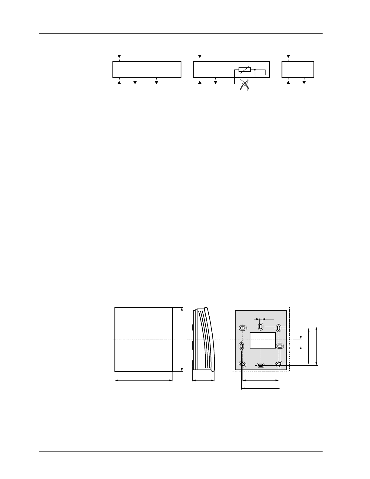
Internal diagram
QFA2060 QFA2020,
QFA2040 (serie B or higher)
QFA2000
G0
U1 U2
G
1857G01
r.h.
R1 = −35...+35 °C /
R2 = 0...50 °C
G0
U1 BS
G
1857G02
r.h.
MS
G0
U1
G
1857G03
r.h.
G, G0 Operating voltage AC 24 V (SELV) or DC 13.5...35 V
U1 Signal output DC 0...10 V for relative humidity 0...100 %
U2 Signal output DC 0...10 V for temperature range 0...50 °C (R2 = factory setting)
or − 35...+35 °C
BS, MS Signal output LG-Ni 1000 oder T1 (passive, simulated) for temperature range 0…50 °C;
the wires must not be interchanged
Dimensions
90
100
36
4,2
9,5
56
60
56
60
1857M01
Drilling plan
Dimension in mm
…
.
.
©2004 Siemens Switzerland Ltd Subject to change
 Loading...