

Siemens QBM Series, QBM3100U025U, QBM3100U1, QBM3100U2.5, QBM3100U5 Installation Instructions Manual
...
Air Differential Pressure Sensors
Product Description
The Siemens QBM Series Air Differential Pressure
Sensors use a well-proven ceramic technology.
They deliver temperature-compensated sensor
signals for registering airflow in HVAC systems and
for the measurement of differential pressures in
environmental, laboratory and cleanroom
applications.
Installation Instructions
Document No. 129-903
October 4, 2013
Expected Installation Time
30 minutes
Prerequisites
Even though the device is protected against electromagnetic interference, installation and cabling must
be carried out correctly to ensure interference
immunity.
Product Numbers
Product Number Percent
Accuracy
QBM3100U025U +/- 0.25
QBM3100U1 1
QBM3100U2.5 2.5
QBM3100U5 5
QBM3100U10
+/-1% FS
Pressure
Range
Inches WC
(Water
Column)
10
Contents
• Sensor
• Conduit Adapter
• Use shielded cables for the signal and control
lines with the connecting lead of the shield
being kept as short as possible. The connection
point of the shielding depends on the existing
connection conditions.
• Never route signal and control cables together
with the trunk line or feeder cables of motors,
cylinder coils, rectifiers, and so on. The cables
must be routed in conductive and grounded
cable conduits. This applies especially to longdistance cables, or environments where the
cables are exposed to strong radio waves from
broad casting stations.
CAUTION:
• Prior to mounting or removing the
• Do not mount sensors in locations
Warning/Caution Notations
WARNING:
CAUTION:
Personal injury/loss of life may
occur if you do not follow the
procedures as specified.
Equipment damage/loss of
data may occur if you do not
follow the procedures as
specified.
• Significant thermal changes in the
sensor, verify that the system is
depressurized.
subject to high pressure pulses.
sensor environment can lead to a zero
shift. As a result, the measuring value
displayed in a depressurized state will
read zero. This kind of drift can be
corrected by zero point reset.
Required Tools
• Small, Phillips screwdriver
• Small, flat-blade screwdriver
• Adjustable wrench
Item Number 129-903, Rev. BA Page 1 of 2
Document No. 129-903
SSEN0024R2
Installation Instructions
October 4, 2013
Installation
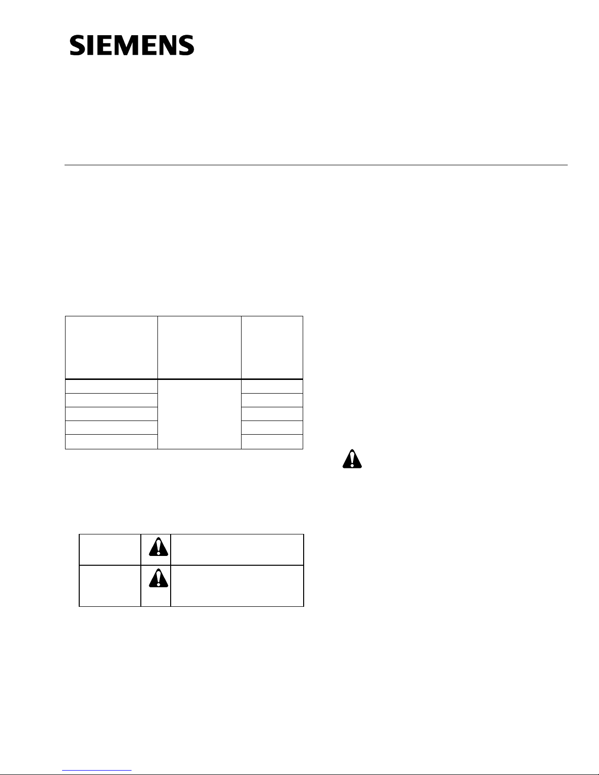
Recommended mounting positions:
• Vertical, with the pressure connections
facing downward, drain off possible
condensed water (factory calibration).
• Horizontal, with the cover facing downward.
• Horizontal, with the cover facing upward.
NOTE: Mount the transmitter with a minimum 0.39
inches (10 mm) distance to magnetic
material. If this is not possible there may be
an error of up to -.004 inch WC for
transmitters mounted on sheet steel.
Figure 1. Recommended Mounting Positions.
Wiring Diagram
Figure 3. Wiring Diagram, 4 to 20 mA.
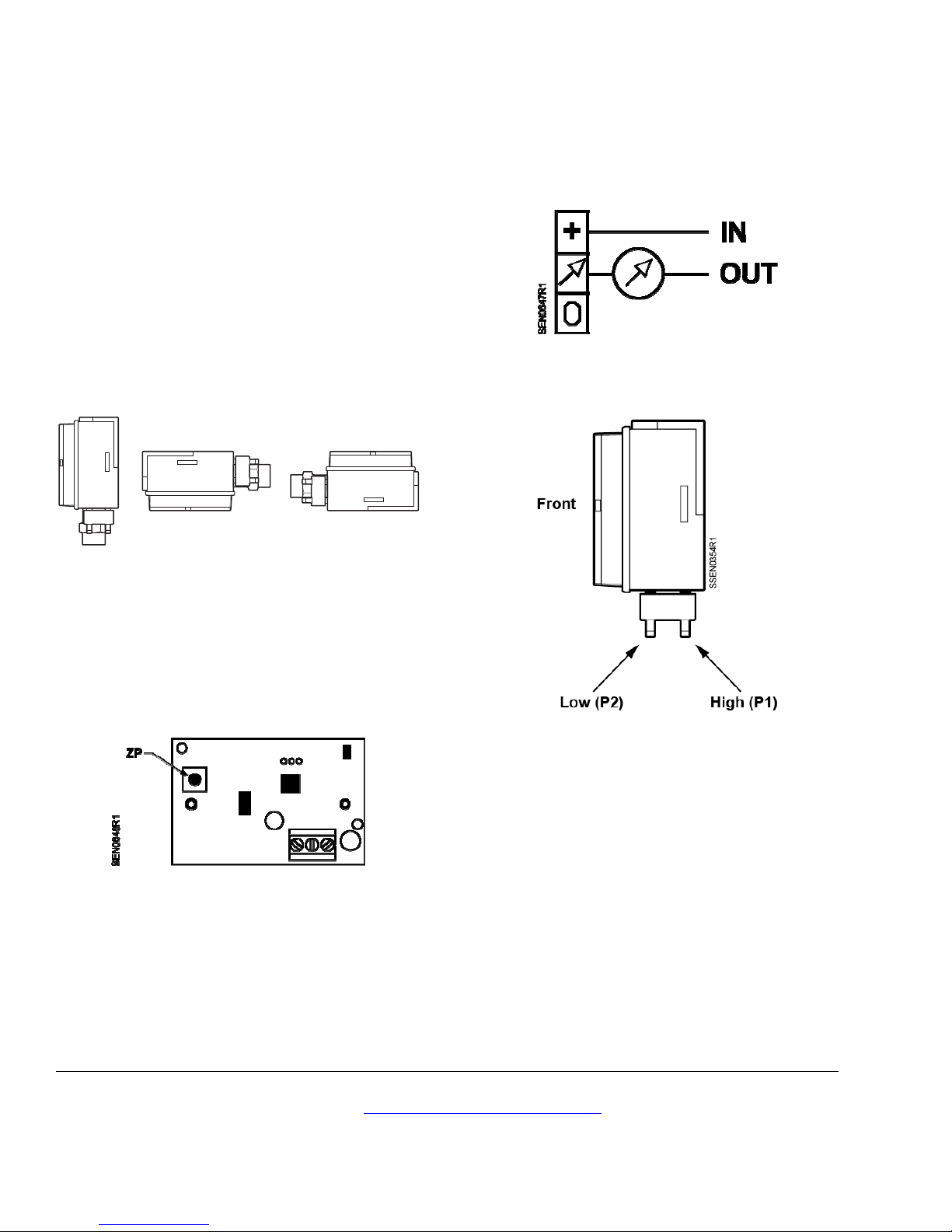
Tubing Connections
ZP – Push Zero Point Reset
The installation position is variable by using the Zero
Point Reset button. Pressure variations can be reset
after installation.
Ensure the power supply is not interrupted when
storing customer settings (ZP – reset).
Figure 4. High and Low Pressure Connections.
The installation is now complete.
Figure 2. ZP Push Zero Point Reset.
Information in this publication is based on current specifications. The company reserves the right to make changes in specifications and
models as design improvements are introduced. Product or company names mentioned herein may be the trademarks of their respective
owners. © 2013 Siemens Industry, Inc.
Siemens Industry, Inc.
Building Technologies Division
1000 Deerfield Parkway
Buffalo Grove, IL 60089-4513
USA
+1-847-215-1000
Your feedback is important to us. If you have
comments about this document, please send them
to SBT_technical.editor.us.sbt@siemens.com
Document No. 129-903
Printed in the USA
Page 2 of 2
 Loading...