

Siemens QBM97 Series User Manual
Modbus air pressure sensor with I/O extension
QBM97..
User Guide
A6V11478123_en_a
Building Technologies
2019
-02-01

Siemens
A6V11478123_en_a
Building Technologies
2019-02-01
2
Contents
Legal note ............................................................................................................. 3
Safety notes in the data sheet ................................................................................... 3
1 Installation ................................................................................................... 4
1.1 Mounting .......................................................................................................... 4
1.1.1 Dimensions ...................................................................................... 5
1.2 Quick release fasteners and detached cover .................................................. 6
1.3 Connecting tubes ............................................................................................ 7
1.4 Wiring .............................................................................................................. 8
1.4.1 Electrical grounding ......................................................................... 8
1.4.2 Power supply ................................................................................... 9
1.4.3 Signal wiring ................................................................................... 10
2 Commissioning .......................................................................................... 12
2.1 Addressing .................................................................................................... 12
2.1.1 DIP switches (Climatix and other controllers) ................................ 12
2.1.2 On-event addressing (Climatix controllers).................................... 13
2.1.3 Baud rate ....................................................................................... 13
2.2 Fault detection, correction or reset ................................................................ 14
3 Engineering ............................................................................................... 15
3.1 Implementing volume flow measurement...................................................... 15
3.2 Modbus registers ........................................................................................... 16
4 Maintenance .............................................................................................. 20
4.1 Zero reset ...................................................................................................... 20
5 Additional information ................................................................................ 21
| 22
Legal note
Safety notes in the data sheet
22
Siemens
A6V11478123_en_a
Building Technologies
2019-02-01
NOTICE
Type and source of hazard
● Measures/prohibitions to prevent the hazard
NOTICE
Comply with all safety notes in data sheet A6V11478118 in the sections
Legal note concept
Qualified personnel
Proper use
Exemption from liability
Legal note
This guide includes notes that must be followed for your own personal safety as
well as to prevent damage to property.
Notes dealing only with damage to property do not have the warning triangle and
use the signal word NOTICE and an exclamation point.
The notes are depicted as follows:
Consequences in the event the hazard occurs
Only qualified personnel may commission the device/system. In this regard,
qualified personnel have the training and experience necessary to recognize and
avoid risks when working with this device/system.
The device/system described here may only be used in building technical plants
and for the described applications only.
The trouble-free and safe operation of the device/system described here requires
proper transportation, correct warehousing, mounting, installation, commissioning,
operation, and maintenance.
You must comply with permissible ambient conditions. You must comply with the
information provided in the Section "Technical data" and any notes in the
associated documentation.
Fuses, switches, wiring and grounding must comply with local safety regulations for
electrical installations. Observe all local and currently valid laws and regulations.
The content of this document was reviewed to ensure it matches the hardware and
firmware described herein. Deviations cannot be precluded, however, so that we
cannot guarantee that the document matches in full the actual device/system. The
information provided in this document is reviewed on a regular basis and any
required corrections are added to the next edition.
Safety notes in the data sheet
"Technical data" and "Notes".
3 |
Installation
Mounting
1
4
Siemens
A6V11478123_en_a
Building Technologies
2019-02-01
NOTICE
Tip
134
5.5
min. 75
q
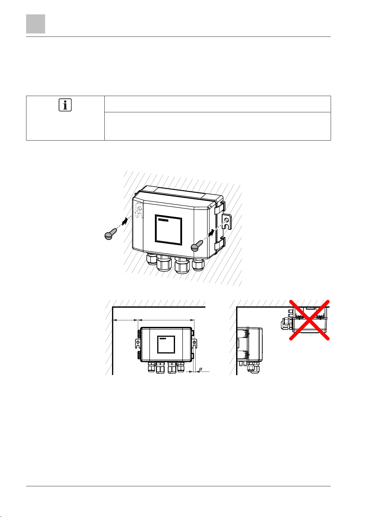
1 Installation
1.1 Mounting
Mount the sensor in a location that is easy to open the cover and access the
terminals, DIP switches and view the LEDs.
Proceed as follows to mount the sensor to a surface:
● Screw the sensor at the 2 brackets (on the device sides) to the mounting
surface.
● Keep the following guidelines
All measurements in millimeters
| 22
Installation
Mounting
1
22
Siemens
A6V11478123_en_a
Building Technologies
2019-02-01
81.9
45
35.5
5
.
5
146
134
60
42
33
11.3
9 10
151.4
175
56
70
28
4
6
3.4
16
6.5
60
78.5
16
100
40
6
1 - 4
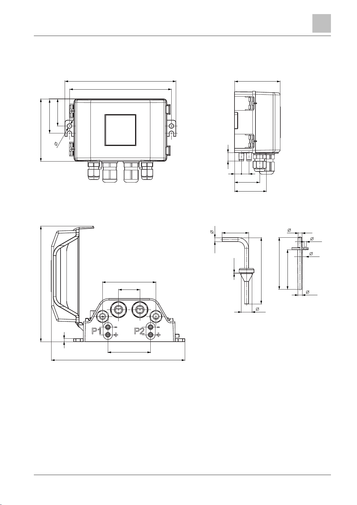
1.1.1 Dimensions
QBM97.. (all dimensions in mm)
Front view QBM97.. (here: without M12) Side view QBM97.. (here: without M12)
Bottom view QBM97.. (opened cover) AQB9120/101A and AQB9220/101A
5 |
Installation
Quick release fasteners and detached cover
1
6
Siemens
A6V11478123_en_a
Building Technologies
2019-02-01
1
1
2
90°
2
2
1
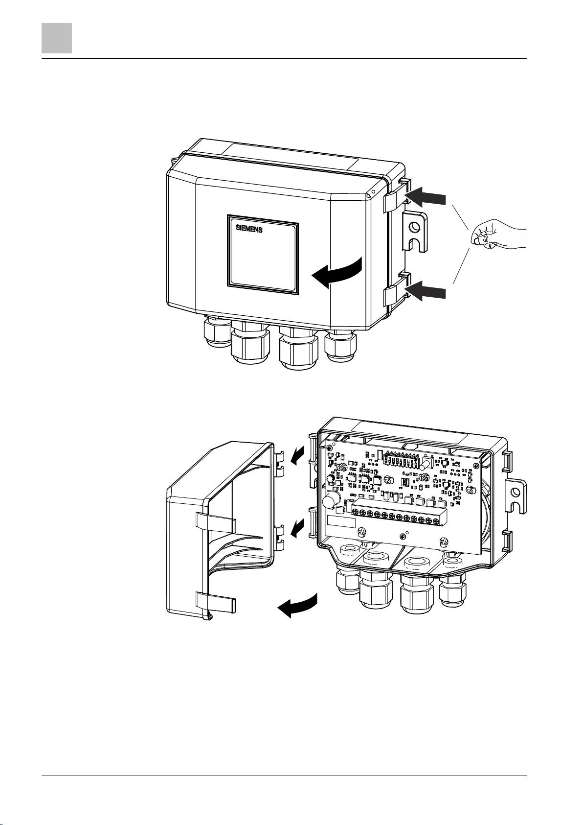
1.2 Quick release fasteners and detached cover
● Open the housing with the quick release fasteners
● The cover can easily be detached completely
| 22
Installation
Connecting tubes
1
22
Siemens
A6V11478123_en_a
Building Technologies
2019-02-01
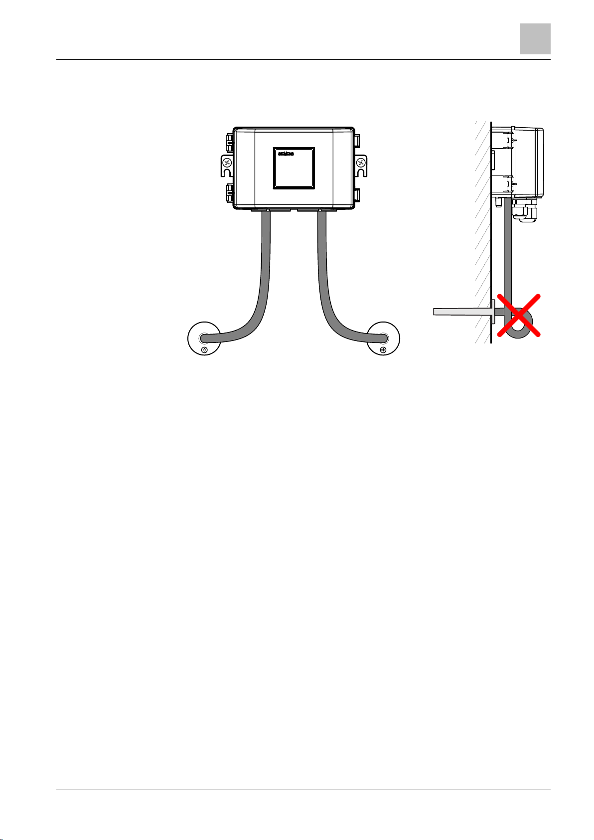
1.3 Connecting tubes
Connect the tubes Avoid loops
7 |
 Loading...