

Siemens QAX850 User Manual
A
722
2
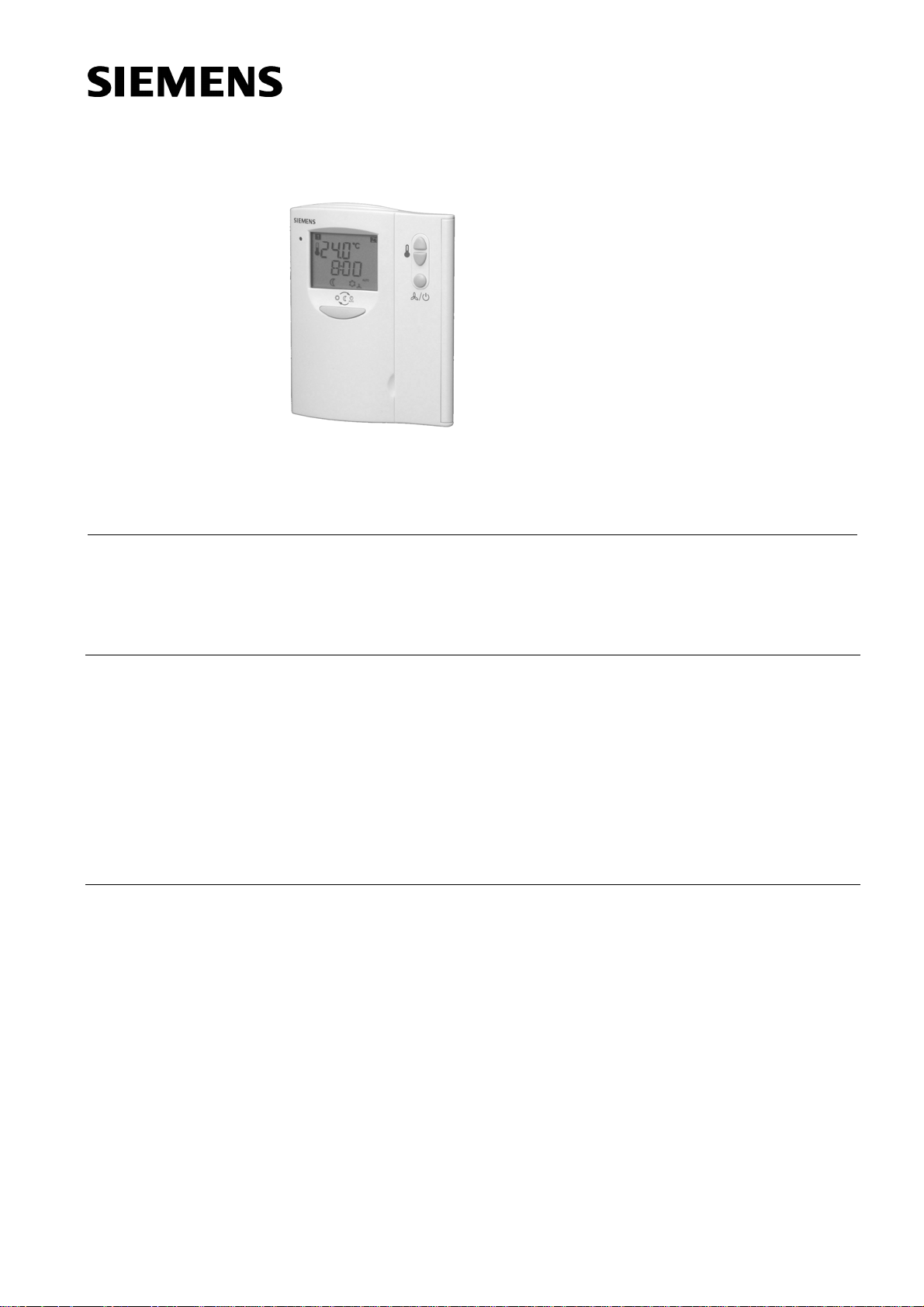
Master room unit
Use
for RRV… controllers
Multifunctional, digital room unit for installer and end-user interface with RRV…
controllers.
2 wire bus connection
QAX850
Use
pplication
Functions
Primary functions
Operator functions
Room unit in combination with an RRV… controller for HVAC plants in:
• Residential apartments
• Residential single house
• Autonomous light commercial applications
For use with RRV… controllers in air based plants including heating, cooling and
ventilation (HVAC) equipment. Suitable for Standard, Duo-zone, Duo-switch and Multizone applications.
• Remote control and monitoring of an RRV… controller
• Parameter adjustments by installer
• Room temperature measurement
• Time clock operation
• Comfort temperature setpoint adjustment
• Energy saving temperature setpoints adjustment
• Auto timer selection
• Fan speed selection
• Zone selection and settings (only for RRV controllers with zone outputs)
• Display of operating mode, temperature, time, fan speed and zone values.
CE1N2722en
28.08.2007
Building Technologies
HVAC Products
Type summary
Product documentation
Mechanical design
Type reference Description Compatible with*
QAX850
Master room unit • Temperature controller RRV851
• Temperature controller RRV852
• Temperature controller RRV856
• Zone room unit QAW850
* Not usable with Desigo RX range of controllers
Document Document number
Data sheet N2722
Mounting instructions M2721
Operating instructions for use with RRV81 B2725en01
Operating instructions for use with RRV82 B2726en01
Operating instructions for use with RRV82 (duo-switch) B2726en03
Operating instructions for use with RRV86 B2727en01
Declaration of conformity T2722
Components
Operating elements
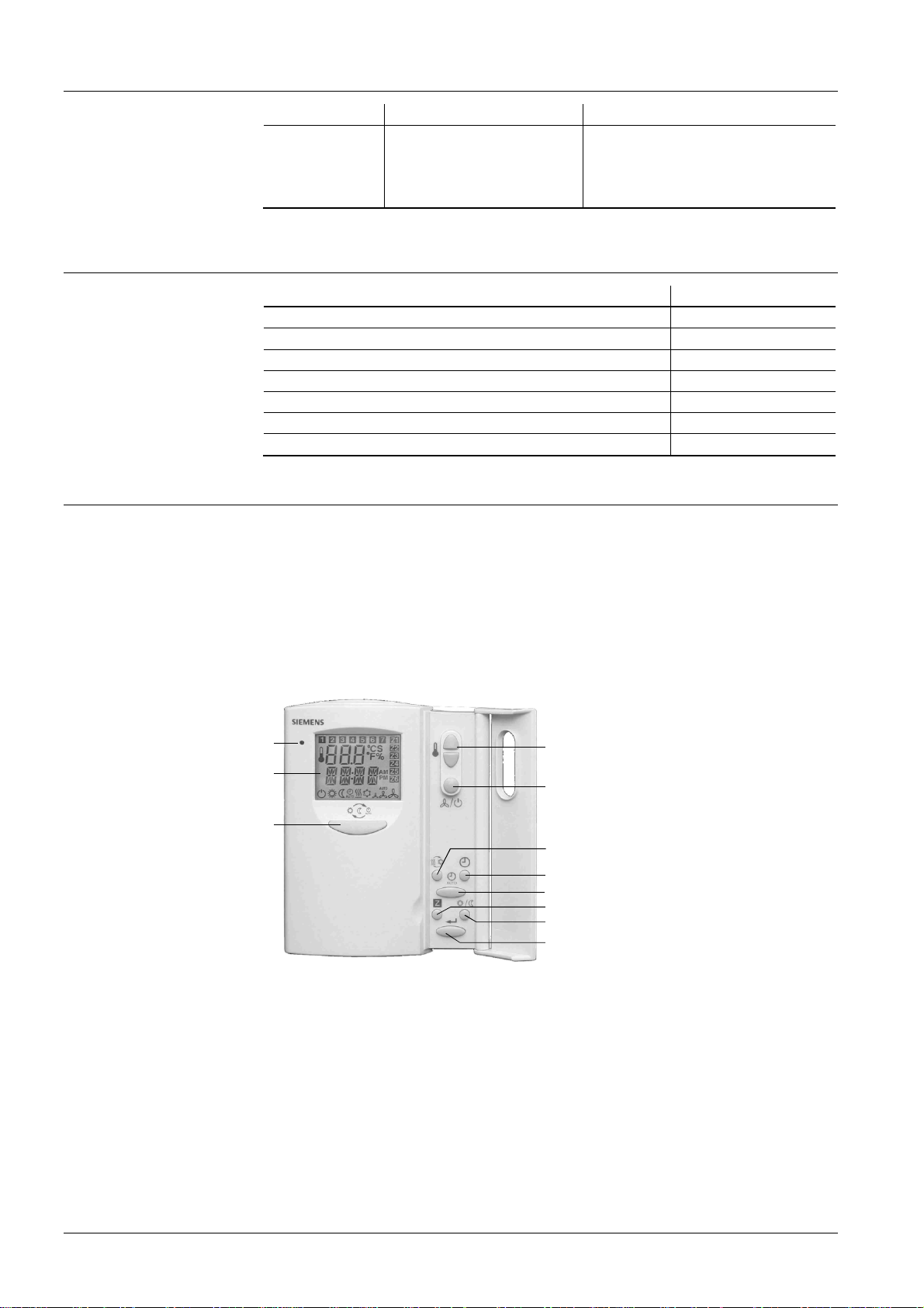
The QAX850 is the installer/OEM/end-user master MMI for RRV controllers.
The unit consists of the following components:
• Room unit with integrated electronics and operating elements
• Internal temperature sensor
• Base for wall mounting with the connection terminals
• Operator interface buttons (high use)
• Operator interface buttons behind door (low use)
2722P01
1
2
3
4
5
6
7
8
9
10
11
1 LED for heat/cool output status
2 LCD display with EL backlight for control and monitoring of modes,
setpoints, zone conditions etc
3 Operating mode selection – Comfort, energy saving and auto timer
(RRV852 Day/Night zone selection for Duo-zone application)
4 Temporary setpoint and value increase/decrease
5 System off and fan speed control
6 Heat, cool, heat/cool changeover and ventilation only selection
7 Time and weekday setting
8 Auto timer schedule setting
9 Zone output selection (RRV856 and RRV852 for Duo-switch application)
10 Permanent comfort and energy saving setpoints (Day/Night/Both setpoints
for RRV852 Duo-zone application)
11 Button for confirming values and scrolling through parameter sets
2/7
Siemens Master room unit QAX850 CE1N2722en
Building Technologies 28.08.2007
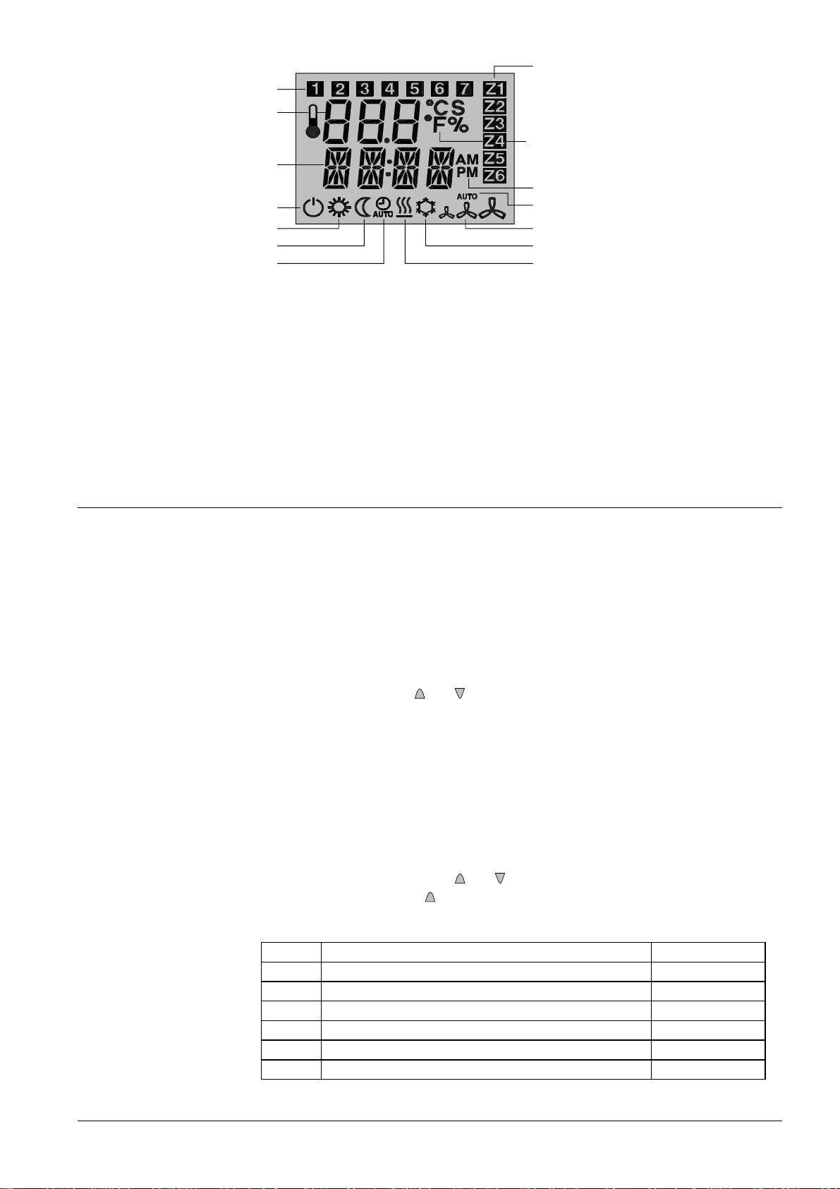
LCD display
1
4
2722Z01
2
3
6
5
7
8
9
10
1 Day indication
2 Actual temperature
3 Fahrenheit/Celsius
4 Zone indication (RRV856 and RRV852 for Duo-switch application)
5 AM/PM indication
6 Time display
7 System off
8 Comfort mode (Day zone in Duo-zone application)
9 Energy saving mode (Night zone in Duo-zone application)
10 Auto timer mode
11 Heating mode
12 Cooling mode
13 Fan speed indication (low, medium and high)
14 Auto fan mode
14
13
12
11
Commissioning notes
Response on start-up
Sensor calibration
Commissioning
Set-up parameters
When powering up, the QAX850 will display all LCD icons for approximately 3 seconds
and then the software version number for another 3 seconds. It will then revert to
normal display. The time segments will be blinking if time needs to be set. Set time as
per Operation Instructions. There will be a delay before operation commences due to
polling of all values.
Generally there is no need to calibrate sensor; however the displayed room
temperature on the LCD can be calibrated if there is any discrepancy from the actual
temperature measured with a certified thermometer. Calibration function can be
accessed by pressing the
and buttons simultaneously for 5 seconds. Displayed
value can then be adjusted via the same buttons in 0.1K steps. Range is ±3 K.
Initial application set-up of RRV controller to match the connected HVAC equipment is
made by the selection of dip switch positions. Dip switches are located on the top of the
RRV controller. Further settings can be made via the QAX850 by modifying parameters
as per list below. Default values are dependant on application selected and RRV
controller model. Refer to Installation Instructions for set-up details and application
sheets for default parameter values.
To access parameters press the
within 2 seconds press the
and buttons simultaneously for 3 seconds, then
button for 3 seconds and release. Parameters cannot be
accessed if system is in off mode.
No. Parameter Range
P00 Temperature scale °C/F°
P01 Frost protection limit in OFF mode Off/5…8 °C
P02 Over-temperature limit in OFF mode Off/30…35 °C
P03 Min. OFF time delay 0…600 s
P04 Min. ON time delay 0…600 s
P05 Dead band between cool and heat OFF points
0.5…6 K
3/7
Siemens Master room unit QAX850 CE1N2722en
Building Technologies 28.08.2007
 Loading...