

Siemens QAX34.1 User Manual
CA2N1645en_02
30 Jun 2009
Building Technologies
1
645
DESIGO™ RX
Room unit with PPS2
interface
QAX34.1
for use with: – devices of the ranges DESIGO RXC, RXB, RXL, and RXA (PPS2)
– DESIGO PX Automation stations
1)
– devices with a PPS2 interface
Room temperature measurement
Rocker switch for adjustment of the room temperature setpoint
Rocker switch for control mode selection (
/ Auto) and manual control of
the fan in fan-coil systems (up to 3 speeds)
PPS2 interface to controller
LCD with room temperature and control mode display
Socket for commissioning and service tool or service terminal
Use
The room unit is used in rooms controlled by an individual room control system, to measure the room temperature and for operation of the room controller. The functions of the
LCD display are determined by the controller. If manual fan-speed control is enabled,
the room unit is suitable for control of a fan-coil system.
It can also be used in conjunction with a DESIGO PXC… automation station
1)
.
The room unit incorporates a socket for a commissioning and service tool or service
terminal. This tool socket provides access via the PPS2 interface or via a bus system
(e.g. L
ONWORKS® bus) to the connected individual room controller.
1) If room units QAX32.1, QAX33.1, QAX34.1, or QAX84.1 are used in conjunction with a PXC automation station, the room unit will show the request of the user and not the effective state.
2/8
Siemens QAX34.1 – Room unit with PPS2 interface CA2N1645en_02
Building Technologies 30 Jun 2009
Ordering
When ordering, please specify the quantity, product name and type code.
Example:
30 Room units QAX34.1
Equipment combinations
The room unit is suitable for use in conjunction with all controllers which incorporate a
PPS2 room unit interface (e.g. DESIGO RX, DESIGO PX).
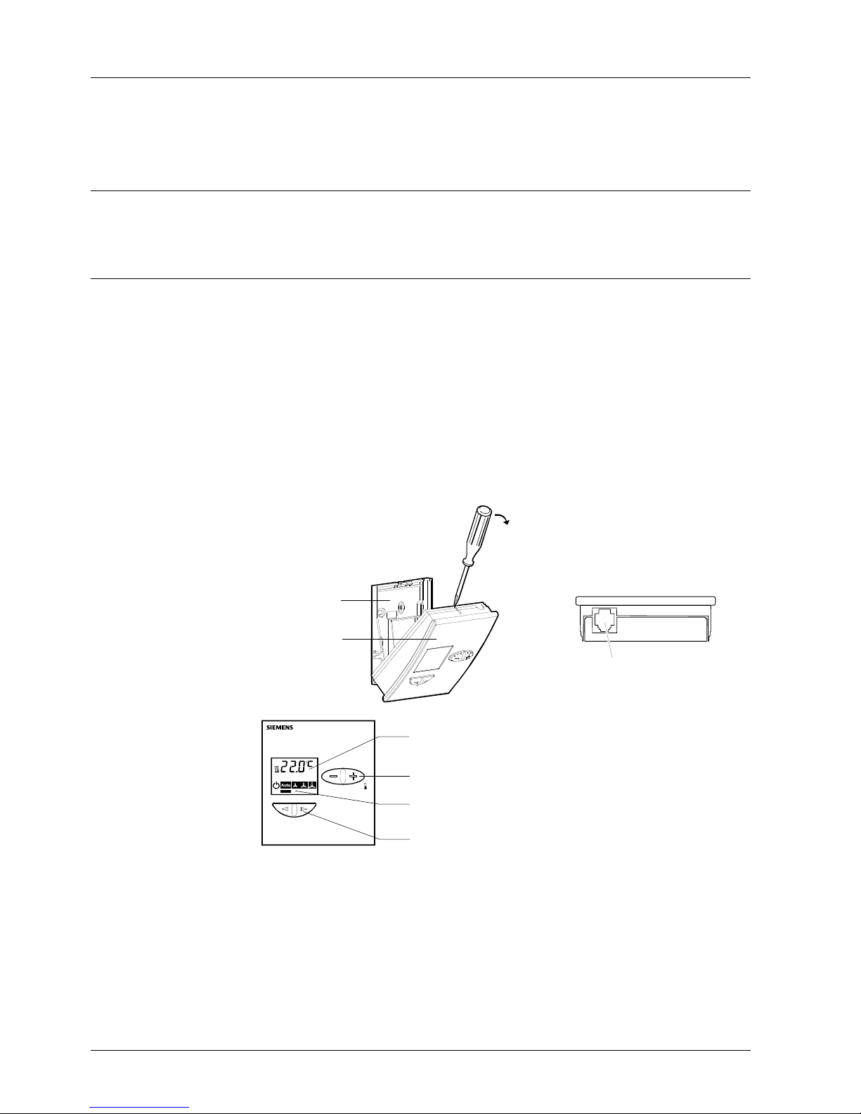
Mechanical design
The room unit is designed for surface mounting (with knock-outs for cable entry from
the top or bottom) or for mounting on a recessed conduit box with the cables connected
from the rear.
The unit comprises a housing and base unit, connected by releasable snap-fittings.
The base unit accommodates the screw terminals which have an integrated terminal
strip.
The housing accommodates a printed circuit board, room temperature sensor element,
setpoint adjuster, rocker switch for mode selection and fan speed selection, plug-in
connectors and a socket for the commissioning and service tool or service terminal.
Both the housing and base are made of plastic.
Base unit
Housing
80083
80084
Socket for the commissioning
and service tool or service
terminal
80166A
Room temperature display and sequence (heating or cooling)
Rocker switch for room temperature setpoint adjustment
Indication of current control mode or current fan speed
Rocker switch for mode selection and fan speed
The actual functions of the operator controls and indicators are determined by the controller (based on the selected application and associated parameters). The description
below covers all possibilities for these items.
The controller control mode can be selected on the basis of occupancy, using the
rocker switch on the room unit. The same switch can also be used for manual selection
of up to three fan speeds.
Operator controls
and indication
Note
Rocker switch for mode
selection and fan speed
3/8
Siemens QAX34.1 – Room unit with PPS2 interface CA2N1645en_02
Building Technologies 30 Jun 2009
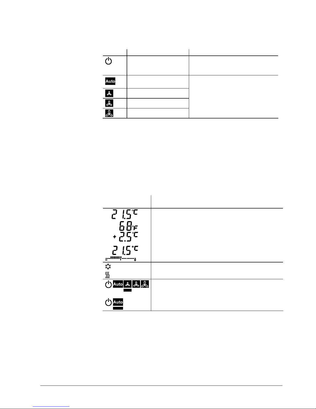
Pressing once in the direction of the left arrow switches one stage to the left, and pressing once in the direction of the right arrow switches one stage to the right. The current
control mode or the manually selected fan speed is indicated in the display panel by a
horizontal bar below the associated symbol.
Position Fan speed control
1)
Control mode
1)
Fan controlled automatically by controller
The controller operates at the setback
setpoints (at night, or when room is unoccupied or occupied intermittently)
Fan controlled automatically by controller
Comfort mode (room occupied)
Manual, fan speed 1
Manual, fan speed 2
Manual, fan speed 3
1) For details of these functions, refer to the application description for the relevant controller range
Press the switch once to switch from a display of the current room temperature to a
display of the setpoint. Each further operation of the
+ or – switch raises or lowers the
setpoint by 0.5 K or 1.0 °F (the unit of measurement is determined by the controller).
The controller also determines the maximum adjustment range allowed.
In normal operation, the following may be displayed (depending on the controller configuration). For details of these functions, refer to the application description for the
relevant controller range.
Display element
(examples)
Description
Room temperature in °C (resolution 0.5 °C)
Room temperature in °F (resolution 1.0 °F)
Digital display of setpoint adjustment
(displayed only while relative adjustment is in progress).
Digital display and scale
(displayed only while absolute adjustment is in progress)
Control sequence: Cooling
Control sequence: Heating
Room units with mode and fan-speed selection enabled:
Fan speed 1: ON
In room units allowing mode selection only:
Auto: ON
Rocker switch room for
temperature setpoint
adjustment
LCD display
 Loading...