

Page 1
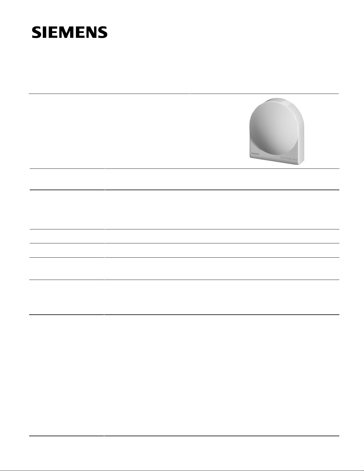
QAC22
Outdoor Sensor
Technical Instructions
Document No. CE1N1811E-P25
Rev. 3, October, 2002
Description
Application
Product Number
Ordering
Equipment
Combinations
Mechanical Design
Specifications
The outdoor sensor measures the outside temperature and, to a lesser degree, solar
radiation, the effect of wind and the temperature of the wall.
The sensor is used as a:
• Reference sensor for weather-dependent flow temperature control.
• Measuring sensor for optimization functions, value display or for connection to a
building management system.
QAC22
When ordering, specify qua ntity, product number and descriptio n.
The QAC22 is suitable for use with all types of controllers that can handle analog
passive sensor signals.
The sensor has a plastic casing with a removable cover. The connection terminals can
be accessed after removing the cover. Cable entry is either from the rear (concealed
wiring) or from below (surface-run wires). A cable entry gland PG11 can be screwed
into the bottom of the casing.
Measuring range –58°F to 158°F (–50°C to 70°C)
Sensing element LG-Ni 1000
Accuracy ±0.4K @ 32° F (0°C)
Time constant Approximately 14 minutes
Permissible ambient conditions
Storage/transportation
Temperature –13°F to 149°F (–25°C to 65°C)
Humidity <85% rh
Operation
Temperature –58° to 158°F (–50°C to 70°C)
Humidity 0 to 100% rh
Electrical connections Terminals (interchangeable)
Cable entry gland PG11 (can be fitted)
Weight 0.2 lb. (0.76 kg)
Color White
Ω thin film element
Siemens Building Technologies, Inc.
Page 2
Technical Instructions QAC22 Outside Sensor
Document Number CE1N1811E-P25
Rev. 3, October, 2002
1400
R [Ω]
∆ϑ
[K]
2.0
LG-Ni 1000 Sensing
Element
Engineering
Installation
Mounting Location
Mounting Height
1200
1000
800
600
−
50
−
58
SSEN0328R1
−40−30−20−
−40−22−
10 01020304050607080
4 14 32 50 68 86 104 122 140 158 176
Characteristic
[
[˚F]
1.0
0.0
−
1.0
−
2.0
ϑ
C]
˚
−
50
SSEN0329R1
−
58
−40−30−20−
−40−22−
10 0102030405060 80
4 14 32 50 68 86 104 122 140 158 176
ϑ
[˚C]
70
[˚F]
Accuracy
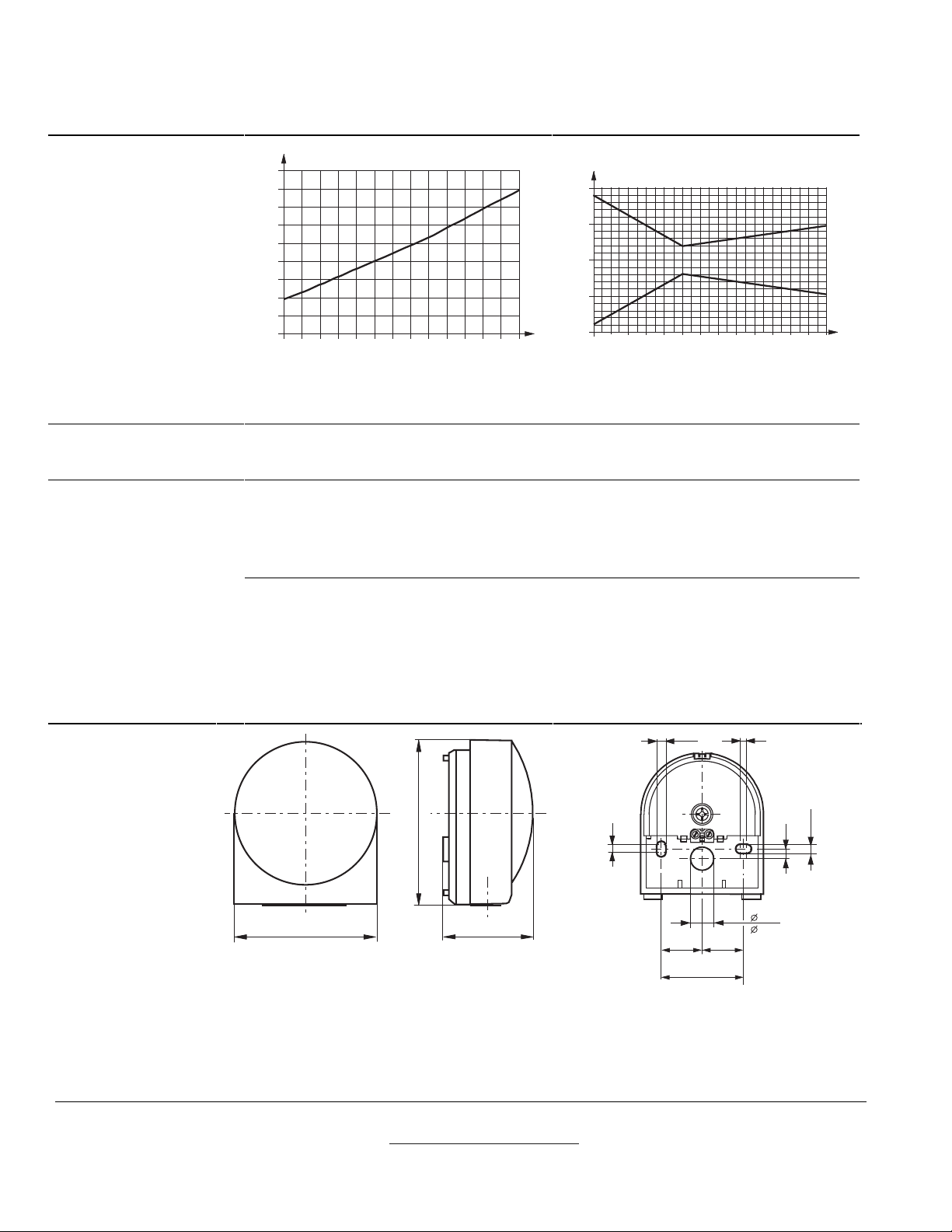
The sensing element changes its resistance value as a function of the temperature.
The controller used with the sensor determines the permissible cable length. See the
controller’s datasheet for cable length.
Locate the sensor based on its use. Do not expose to the morning sun. If in doubt,
mount on the north or northwest wall.
• For control, mount on the occupied room’s wall with windows.
• For optimization, mount on the coldest wall of the building (normally the north wall).
Mount preferably in the middle of the building or heating zone, but at least 8 feet (2.5 m)
above the ground.
Do not install above windows, doors, air diffusers or other heat sources.
Seal the cable conduit at the sensor to prevent measuring errors due to air circulation.
Do not paint over the sensor.
Mounting instructions are p rinted on the packaging.
0.98
(25)
0.12
(3)
0.56
( 14,1)
0.24
0.22
(5,5)
(6)
Dimensions
SSEN0142R3
3.14
(79,8)
0.22
(5,5)
(4)
0.16
1.61
(91,6)
1.86
(49,7)
SSEN0143R3
0.96
(24,5)
1.95
(49,5)
Figure 1. Dimensions in Inches (Millimeters).
Information in this publication is based on current specifications. The company reserves the right to make c hanges i n specifications and models as
design improvements are introduced. Other product or company names mentioned herein may be the trademarks of their respecti ve owners.
© 2002 Siemens Building Technologies, Inc.
Siemens Building Technologies, Inc.
1000 Deerfield Parkway
Buffalo Grove, IL 60089-4513
U.S.A.
Your feedback is important to us. If you have
comments about this document, please send
them to [email protected]
Document No. CE1N1811E-P25
Printed in the U.S.A.
Page 2
 Loading...