

Siemens QAA75 series, QAA58 series, QAA55 series, QAA78 series Technical Manual
CE1U2358en_04
Building Technologies
2014-09-26
Albatros2
Operator units / Room units /
Auxiliary d evices
Technica l Manual


3
Siemens Operator / Room / Auxiliary devices CE1U2358en_04
Building Technologies 2014-09-26
Content
1 Overvie w .........................................................................................................5
2 Mount ing and installati on ...............................................................................9
2.1 Wired components ............................................................................................9
2.1.1 Room unit QAA55… ........................................................................ 10
2.1.2 Room unit QAA75… ........................................................................ 12
2.1.3 Operato r unit AVS37.29 x ................................................................. 14
2.1.4 Operato r unit AVS37 .394 ................................................................. 15
2.1.5 Operato r unit AVS37.390 ... .............................................................. 16
2.2 RF compone nts .............................................................................................. 17
2.2.1 Room unit QAA58… ........................................................................ 18
2.2.2 Room unit QAA78.. . ......................................................................... 21
2.2.3 RF module AVS71.390 .................................................................... 25
2.2.4 RF module BSB AVS71.393 ............................................................ 27
2.2.5 RF repeater AVS14.39 0 ................................................................... 29
2.2.6 RF outside sensor AVS13.3 99 ......................................................... 32
2.2.7 Checking the RF components .......................................................... 36
3 Handling ........................................................................................................ 37
3.1 QAA55. .. / QAA58... ........................................................................................ 37
3.1.1 Operation ......................................................................................... 37
3.1.2 Programming ................................................................................... 41
3.2 QAA75. .. / QAA78… / AVS37… ...................................................................... 42
3.2.1 Operation ......................................................................................... 42
3.2.2 Programming ................................................................................... 53
3.2.3 User levels ....................................................................................... 56
3.2.4 Room unit, operator unit sett ings ...................................................... 58
3.2.5 Setting s in detail .............................................................................. 60
3.3 AVS37.390... .................................................................................................. 68
3.3.1 Operation ......................................................................................... 68
3.3.2 Programming ................................................................................... 73
3.3.3 User levels ....................................................................................... 75
3.3.4 Overview of the settings ................................................................... 76
4 Technic al data............................................................................................... 78
4.1 Operato r unit and room units QAA5 x... / QA A7x... / AVS3 7... .......................... 78
4.2 RF module AVS71.39 0 ................................................................................... 80
4.3 RF module BSB AVS71.3 93 ........................................................................... 81
4.4 RF repea ter AVS14.390.................................................................................. 82
4.5 RF outside sensor AVS13.399 ........................................................................ 83
Index ....................................................................................................................... 84

4
Siemens Operator / Room / Auxiliary devices CE1U2358en_04
Building Technologies 2014-09-26
Overview
1
5
Siemens Operator / Room / Auxiliary devices CE1U2358en_04
Building Technologies 2014-09-26
1 Overview
The room and operator units described in this document operate in an optimum
manner BMUs for floor-standing or wall-mounted boiler controllers. The room and
operator units are suitable for plants that do not require cooling.
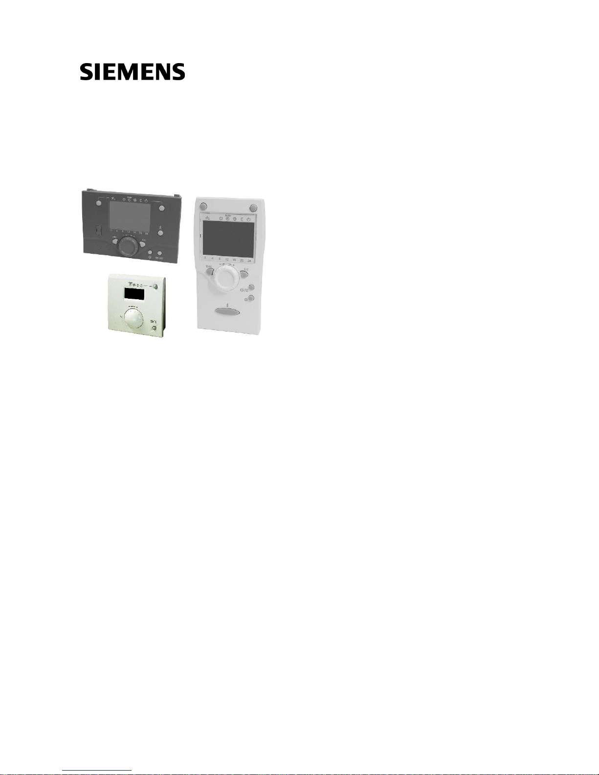
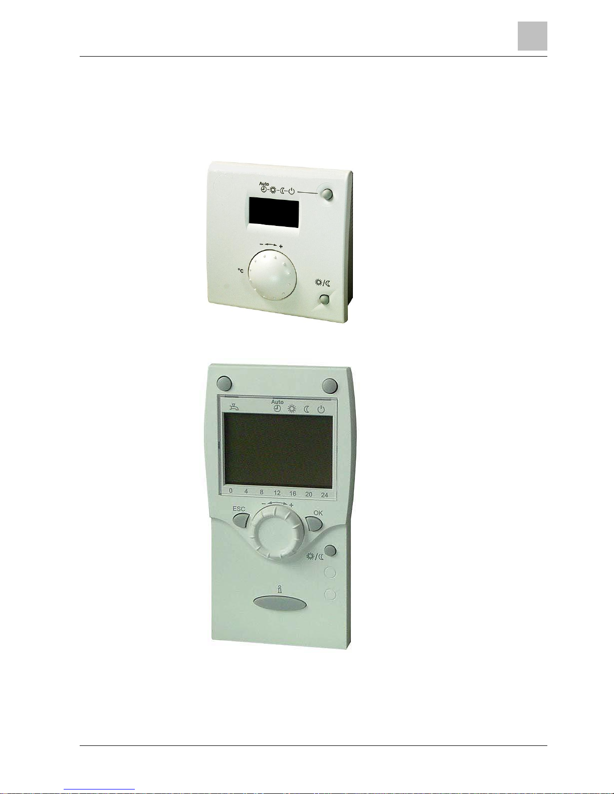
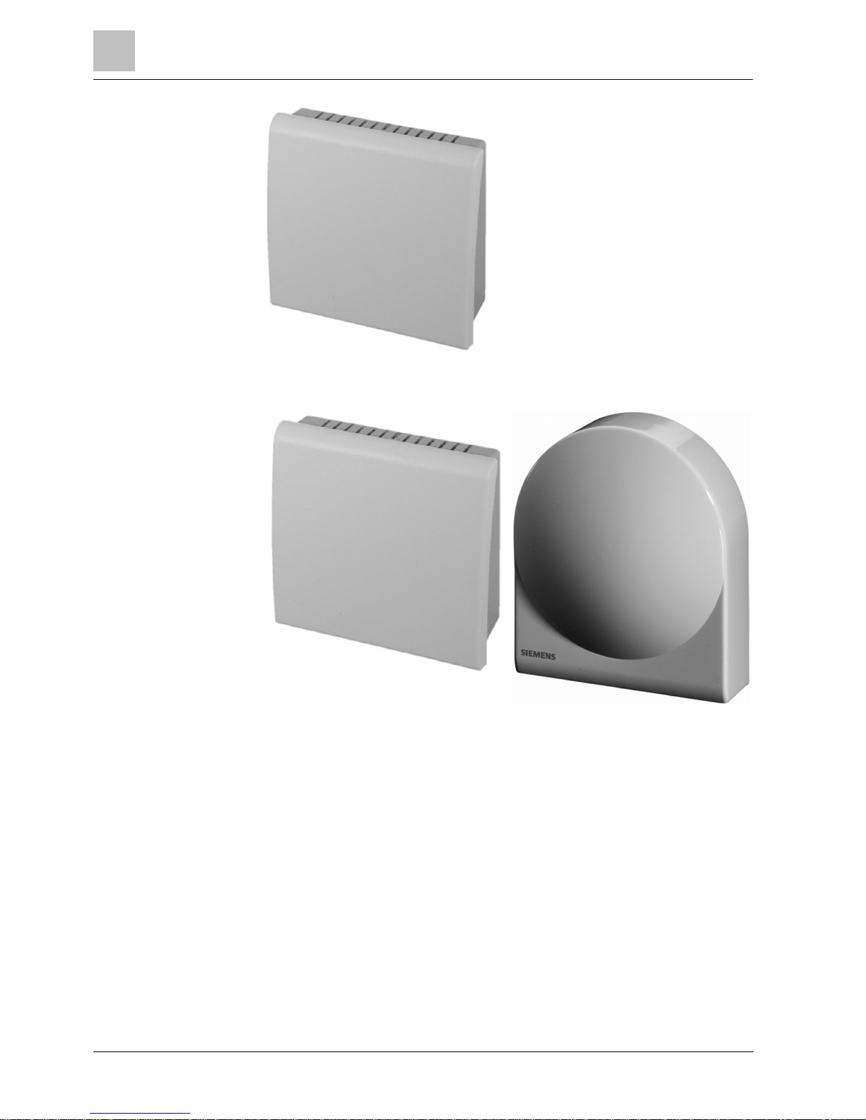
Room unit QAA5x.110/101.
Room unit QAA7x.61x/101, room unit QAA7x.61x/501
This document
List of described dev ices
1
Overview
6
Siemens Operator / Room / Auxiliary devices CE1U2358en_04
Building Technologies 2014-09-26
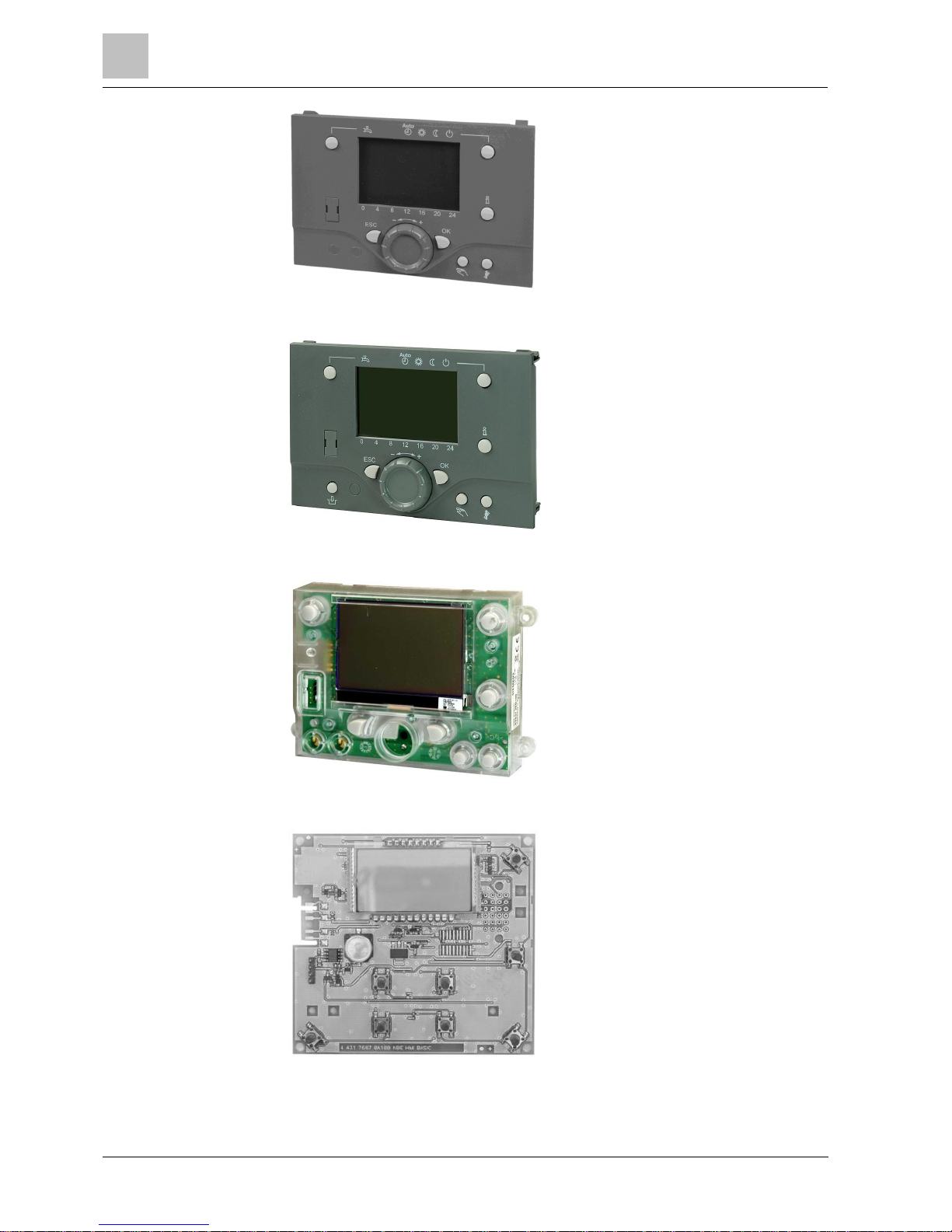
Operator unit AVS37. 294/109, operator unit AVS37.294/509
Operator unit AVS37. 296/109
Operator unit AVS37. 394/109
Operator unit AVS37. 390/209
Overview
1
7
Siemens Operator / Room / Auxiliary devices CE1U2358en_04
Building Technologies 2014-09-26
RF module AVS71.390
RF module BSB AVS71.393
1
Overview
8
Siemens Operator / Room / Auxiliary devices CE1U2358en_04
Building Technologies 2014-09-26
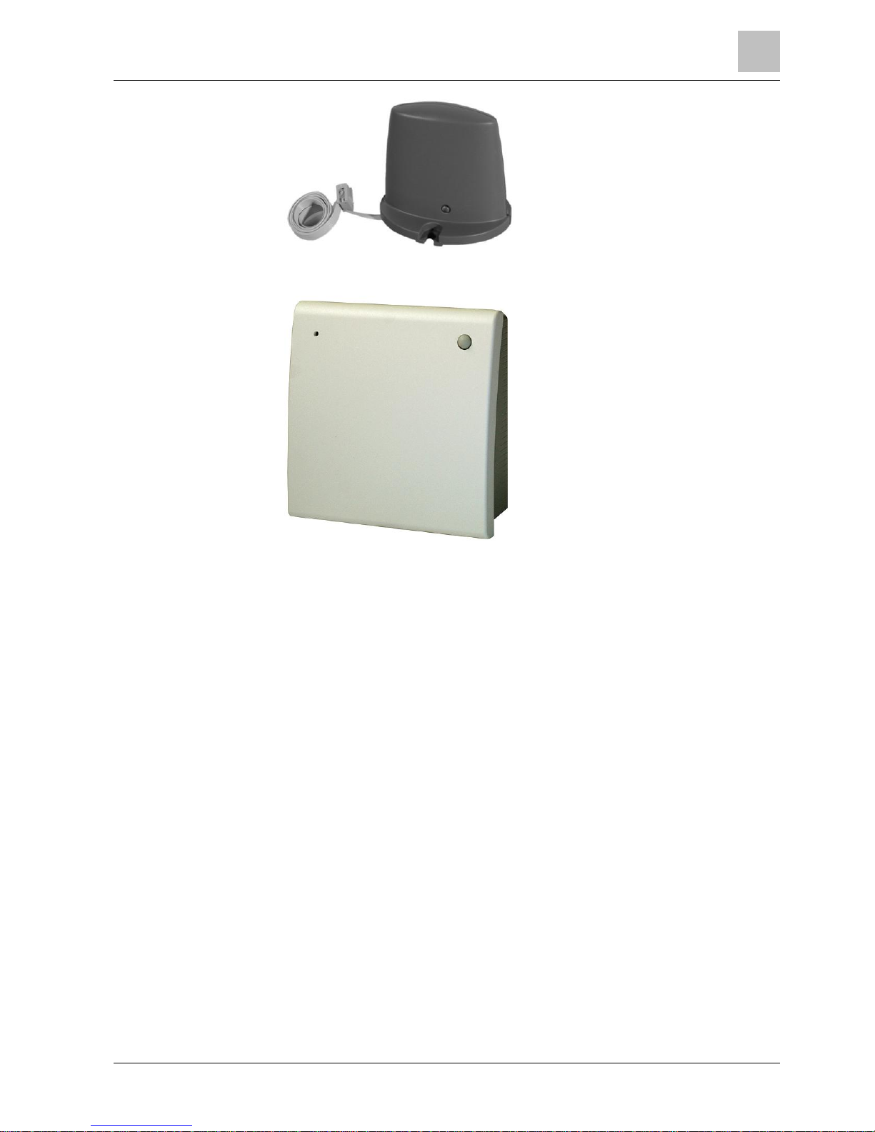
RF repeater AVS14.390
RF outside sensor AVS13.399
Mounting and installation
2
Wired components
9
Siemens Operator / Room / Auxiliary devices CE1U2358en_04
Building Technologies 2014-09-26
2 Mounting and installation
2.1 Wired components
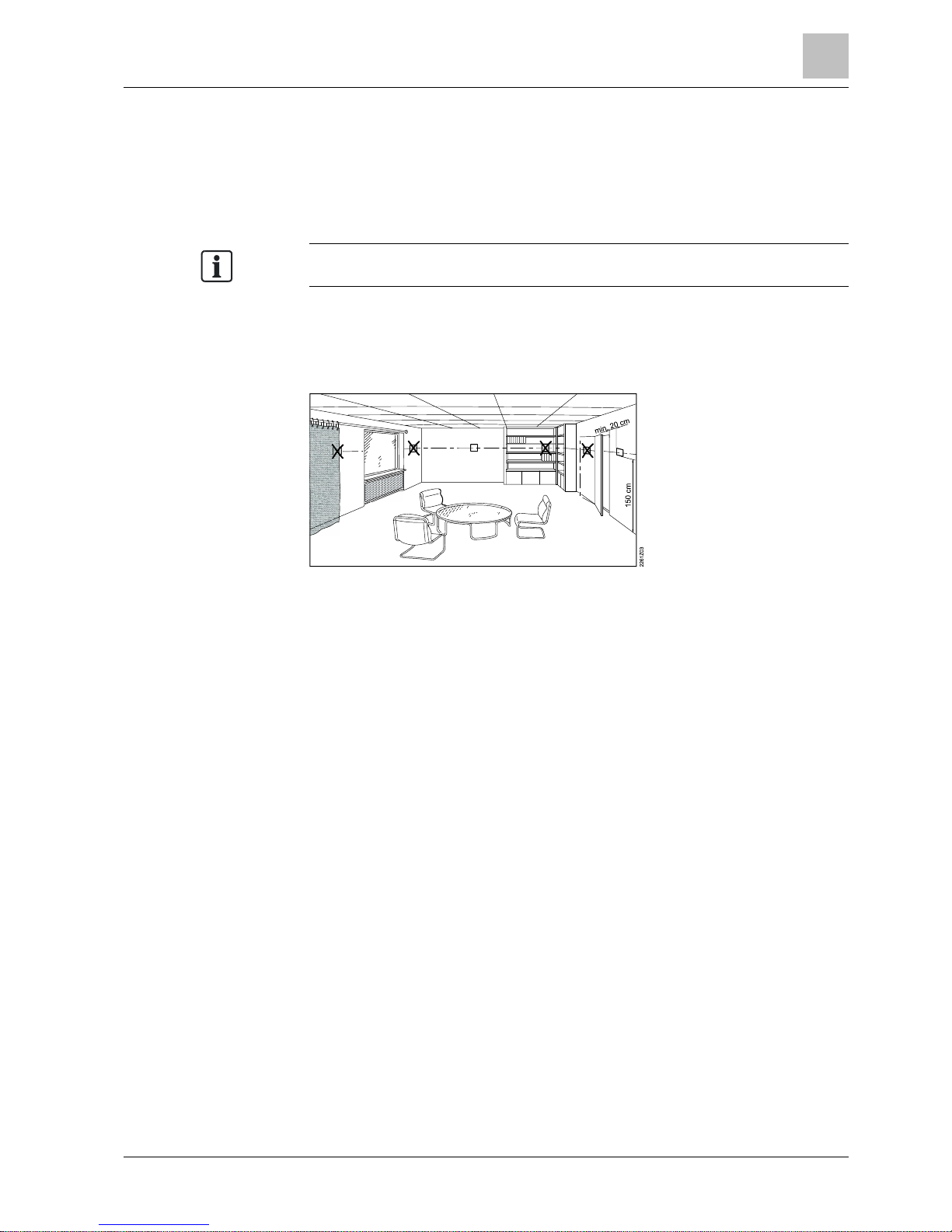
Do not expose devices t o dripping water.
Install room units in the main occupancy rooms.
The place of inst allation should be chosen so that t he sensor can c apture the room
temperature as accurately as possible without getting adv ersely affected by direct
solar radiation or other heat or refrigeration sources (about 1.5 meters above the
floor)
The base provides the power for QAA55 and QAA75. When the units are removed
from the base, power is cut off (i.e. the units are out of operation).
Devices in general
Room units
Powered by base
2
Mounting and installation
Wired components
10
Siemens Operator / Room / Auxiliary devices CE1U2358en_04
Building Technologies 2014-09-26
2.1.1 Room unit QAA55…
1 CL+ BSB data
2 CL- BSB ground
Installation
Connections
Mounting and installation
2
Wired components
11
Siemens Operator / Room / Auxiliary devices CE1U2358en_04
Building Technologies 2014-09-26
Dimensions and dril ling
plan
2
Mounting and installation
Wired components
12
Siemens Operator / Room / Auxiliary devices CE1U2358en_04
Building Technologies 2014-09-26
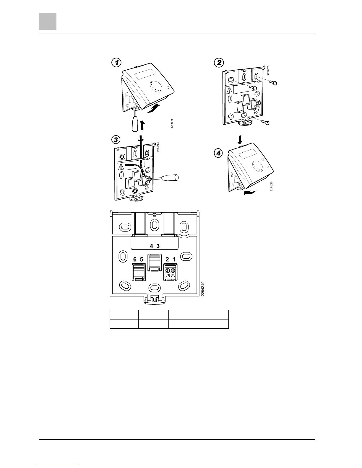
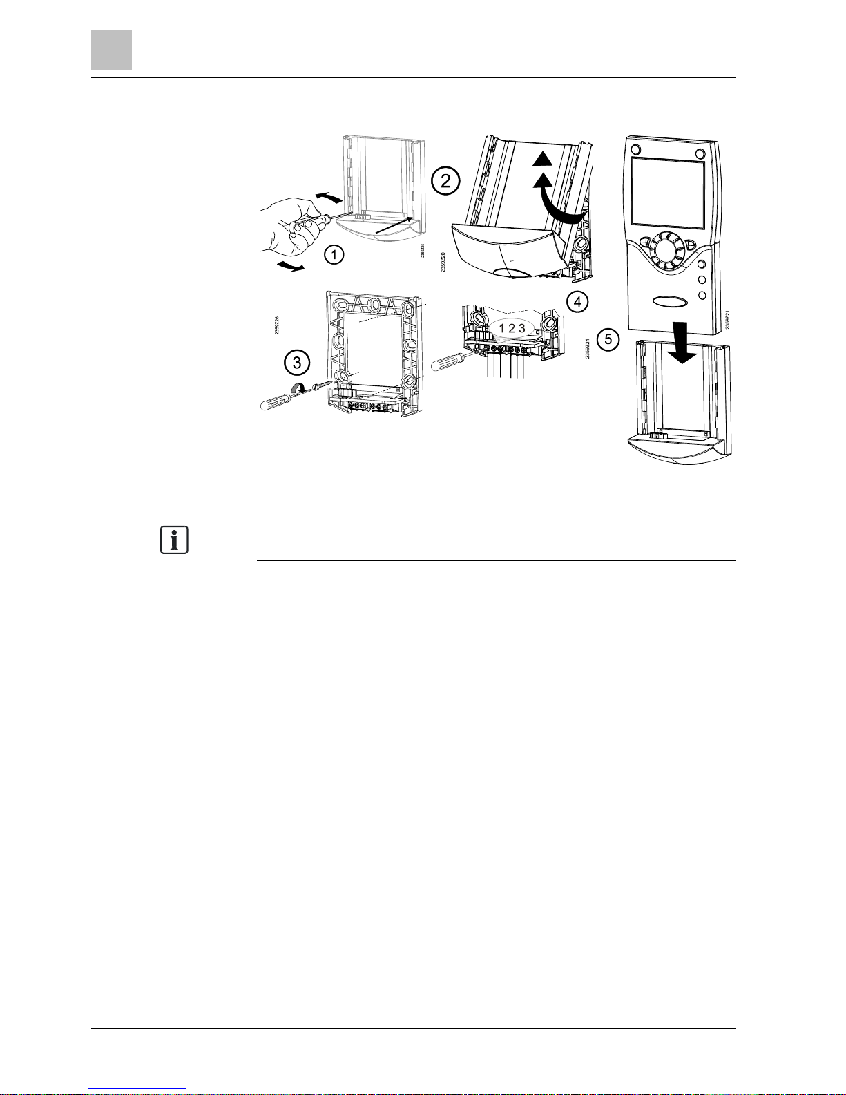
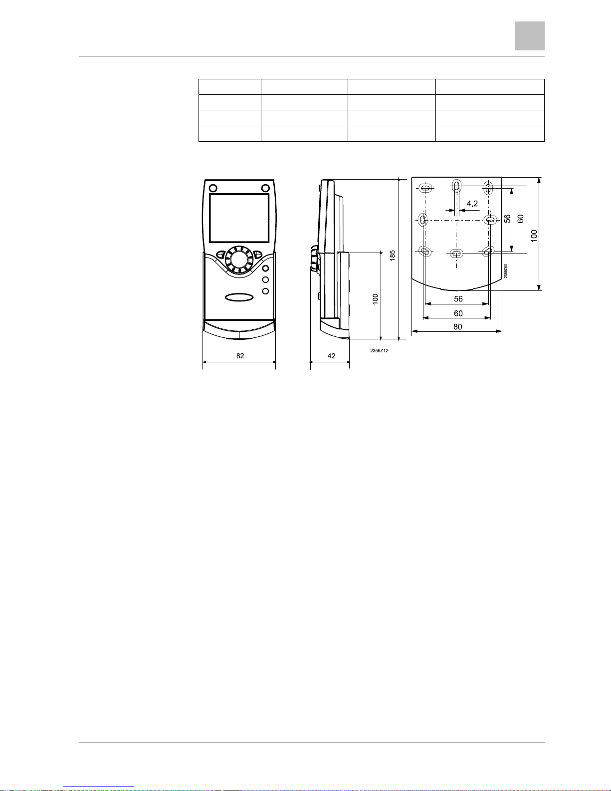
2.1.2 Room unit QAA75…
There must be sufficient clearance above the unit to install and remove it as
needed.
Installation
Mounting and installation
2
Wired compo
nents
13
Siemens Operator / Room / Auxiliary devices CE1U2358en_04
Building Technologies 2014-09-26
Terminal Designation QAA75.610 QAA75.611
1 CL+ BSB data BSB data
2 CL- BSB ground BSB ground
3 G+ Reserved Power supply DC 12 V
Connections
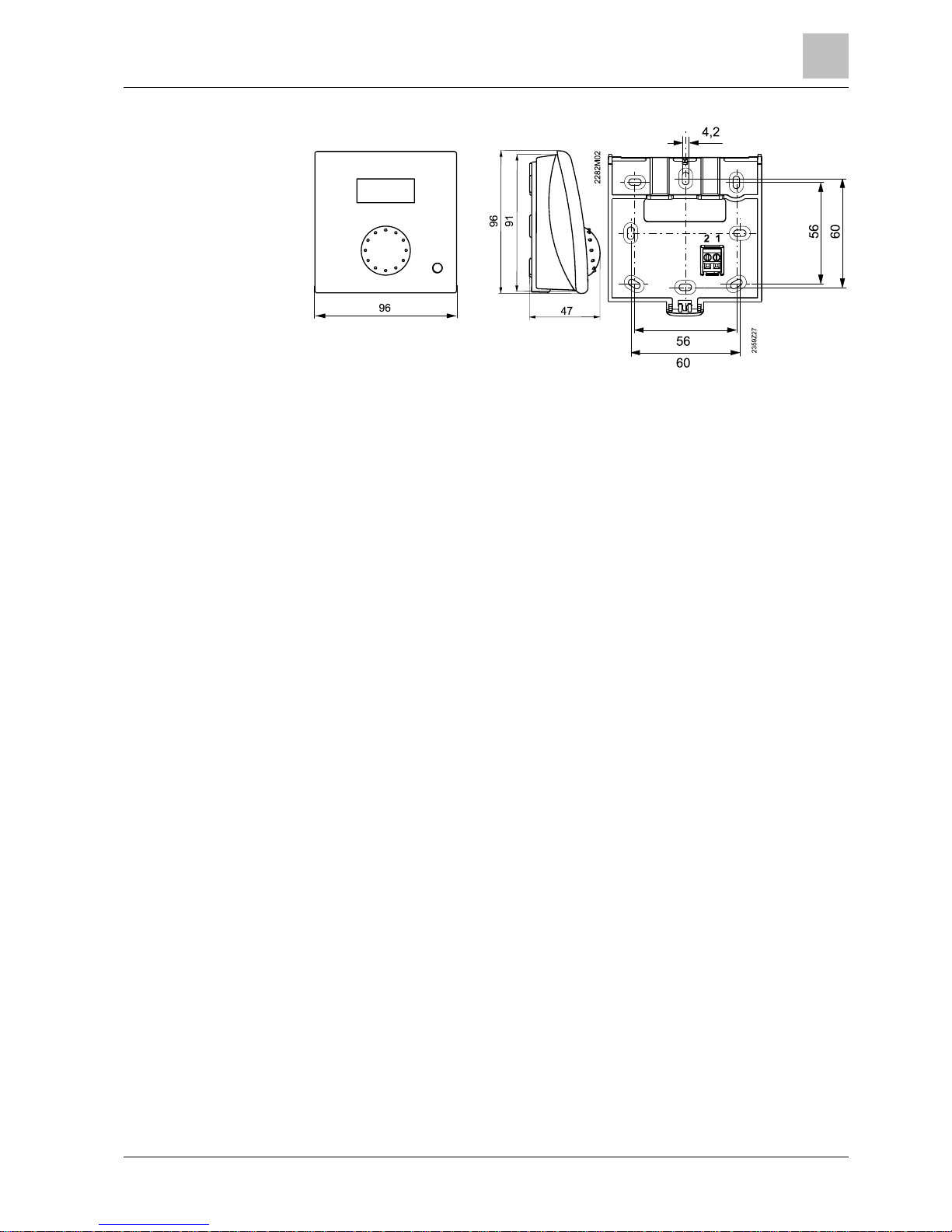
Dimensions and dril ling
plan
2
Mounting and installation
Wired components
14
Siemens Operator / Room / Auxiliary devices CE1U2358en_04
Building Technologies 2014-09-26
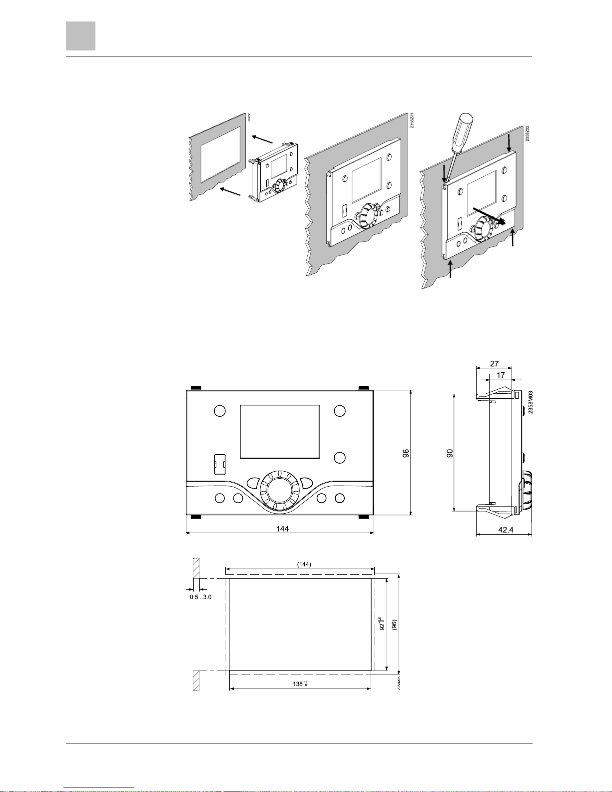
2.1.3 Operator unit AVS37.29x
Installation Removal
The AVS37.294 operator unit must be connected to terminal X30 of the basic unit
using the AVS82.491/109 connecting cable. The connectors are coded.
Installation
Connections
Dimensions
Panel cutout
Mounting and installation
2
Wired components
15
Siemens Operator / Room / Auxiliary devices CE1U2358en_04
Building Technologies 2014-09-26
2.1.4 Operator unit AVS37.394
Siemens supplies operator unit AVS37.394 without a housing.
The AVS37.394 operator unit must be connected to terminal X30 on the basic unit
using the AVS82.491/109 connecting cable. The connectors are coded.
Dimensions
Connections
2
Mounting and installation
Wired components
16
Siemens Operator / Room / Auxiliary devices CE1U2358en_04
Building Technologies 2014-09-26
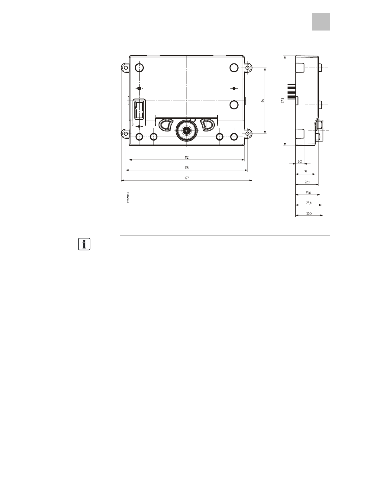
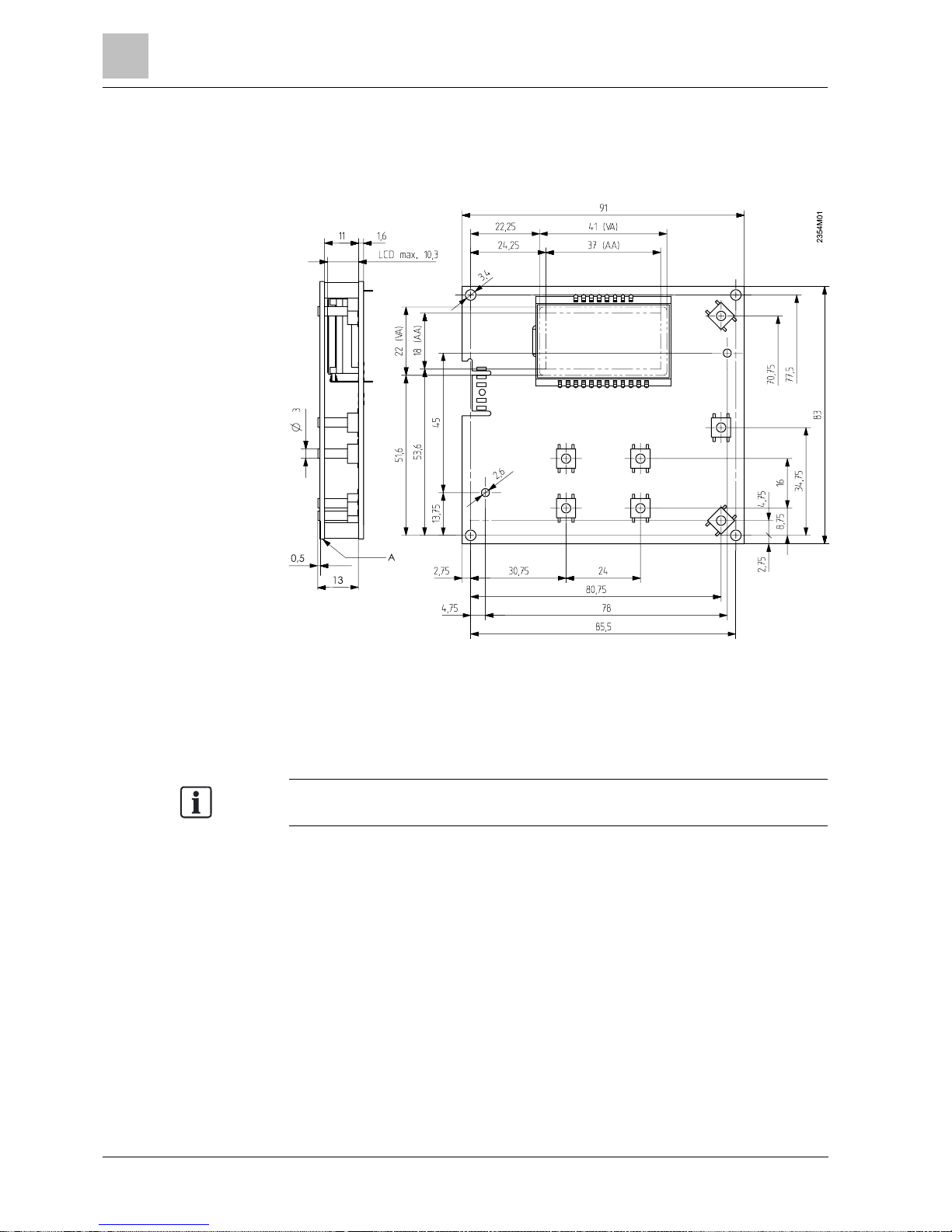
2.1.5 Operator unit AVS37.390...
The AVS37.390 operator unit must be connected to terminal X30 of the basic unit
using the AVS82.491/109 connecting cable. The connectors are coded.
VA Visual area
AA Active area
A Control panel, front
The AVS37.39
0 operator unit is a PCB ver sion without casing, supplied by
Siemens.
Connections
Dimensions
Mounting and installation
2
RF components
17
Siemens Operator / Room / Auxiliary devices CE1U2358en_04
Building Technologies 2014-09-26
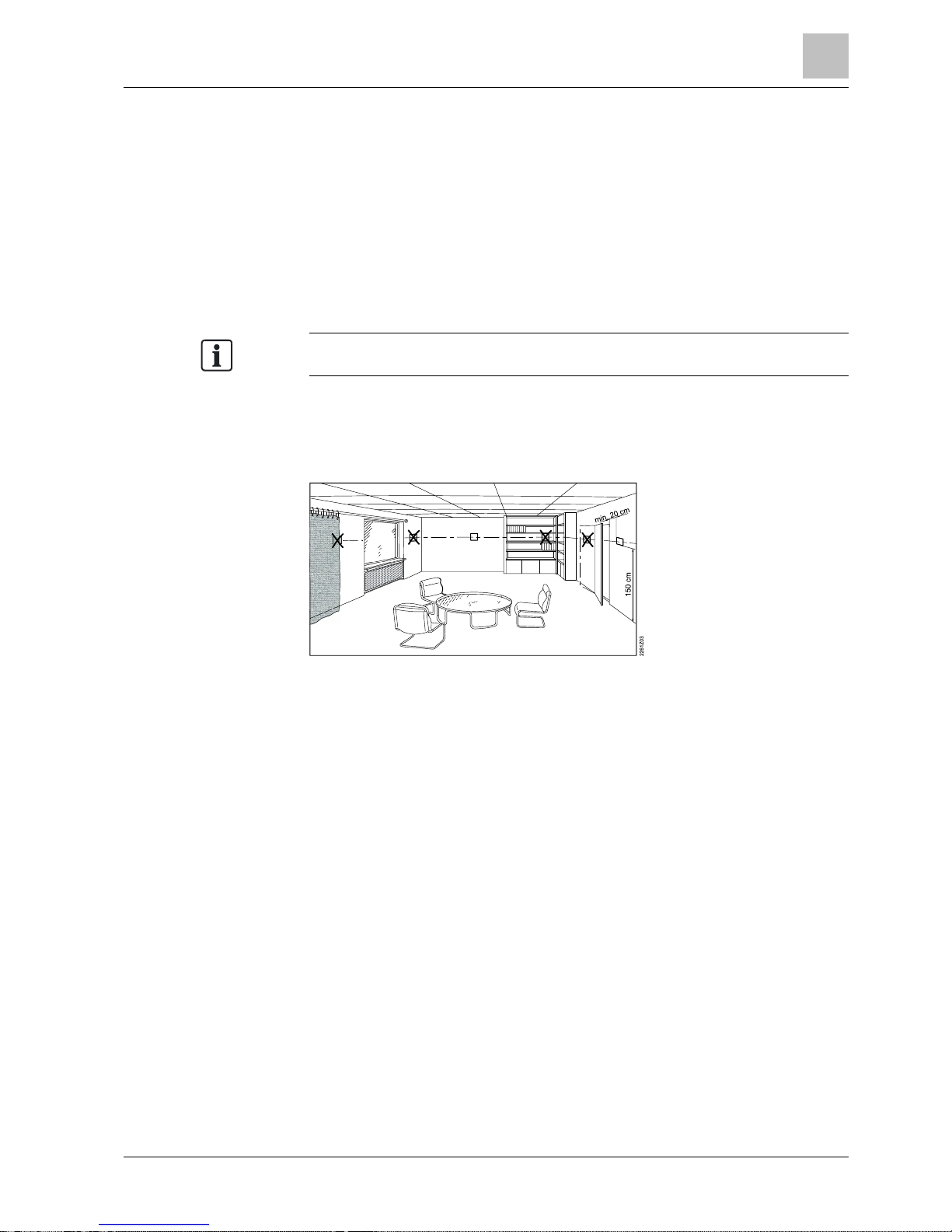
2.2 RF component s
The wireless components should be located suc h that transmission is as
interference-free as possible. For installation, the following points must be
observed:
l Not in the vicinity of electrical cables, strong magnetic fields or equipment such
as PCs, TVs, microwave ovens, etc.
l Not near larger metal structures or constructional elements with fine met al
meshes, such as special glass or concrete.
l The distance to the transmitter should not exceed 30 meters or 2 floors
Do not expose devices t o dripping water.
Install room units in the main occupancy rooms.
The place of inst allation should be chosen so that t he sensor can c apture the room
temperature as accurately as possible without getting adv ersely affected by direct
solar radiation or other heat or refrigeration sources (about 1.5 meters above the
floor)
RF devices in general
Room units
2
Mounting and installation
RF components
18
Siemens Operator / Room / Auxiliary devices CE1U2358en_04
Building Technologies 2014-09-26
2.2.1 Room unit QAA58…
Installation
Dimensions and dril ling
plan
Mounting and installation
2
RF components
19
Siemens Operator / Room / Auxiliary devices CE1U2358en_04
Building Technologies 2014-09-26
NOTICE
●
Establish RF connection while unmounted and near the RF module (BSB).
● The base unit powers the RF module (BSB).
● T he devices battery supply must be activated (remove the battery protective
strip).
1. Press the button on the RF module (BSB) for at least 8 seconds.
a The LED on the RF module (BSB) blinks rapidly.
2. Press the occupancy button for at least 3 seconds.
a The room unit switches to the service level (Display "ru 1").
3. Depending on the heating circuit, turn knob t o "ru 2", "ru 3".
4. Press occupancy button 3 times, until "P3" appears.
5. Press operating mode button.
a The process of opening the connection is started.
a The connection is complete as soon as the LED RF module (AVS71.390) turns
off and the room unit re-st arts.
a The LED of the RF module BSB (AVS71.393) lights again after 5 seconds
(operating stat e "On").
a The room unit displays the room temperature.
Refer to Section
Operation [
➙
37]for button labels.
RF connection
Establishment
2
Mounting and installation
RF components
20
Siemens Operator / Room / Auxiliary devices CE1U2358en_04
Building Technologies 2014-09-26
NOTICE
●
The test is made to check the quality of the radio link.
●
Testing takes place at the final installation location.
1. Press the occupancy button for at least 3 seconds.
a The room unit switches to the service level (Display "ru..").
2. Press occupancy button 4 times, until "P4" appears.
3. Press operating mode button.
a Test mode begins. 24 telegrams are sent.
The test can be stopped by pressing the operating mode or occupancy but
tons.
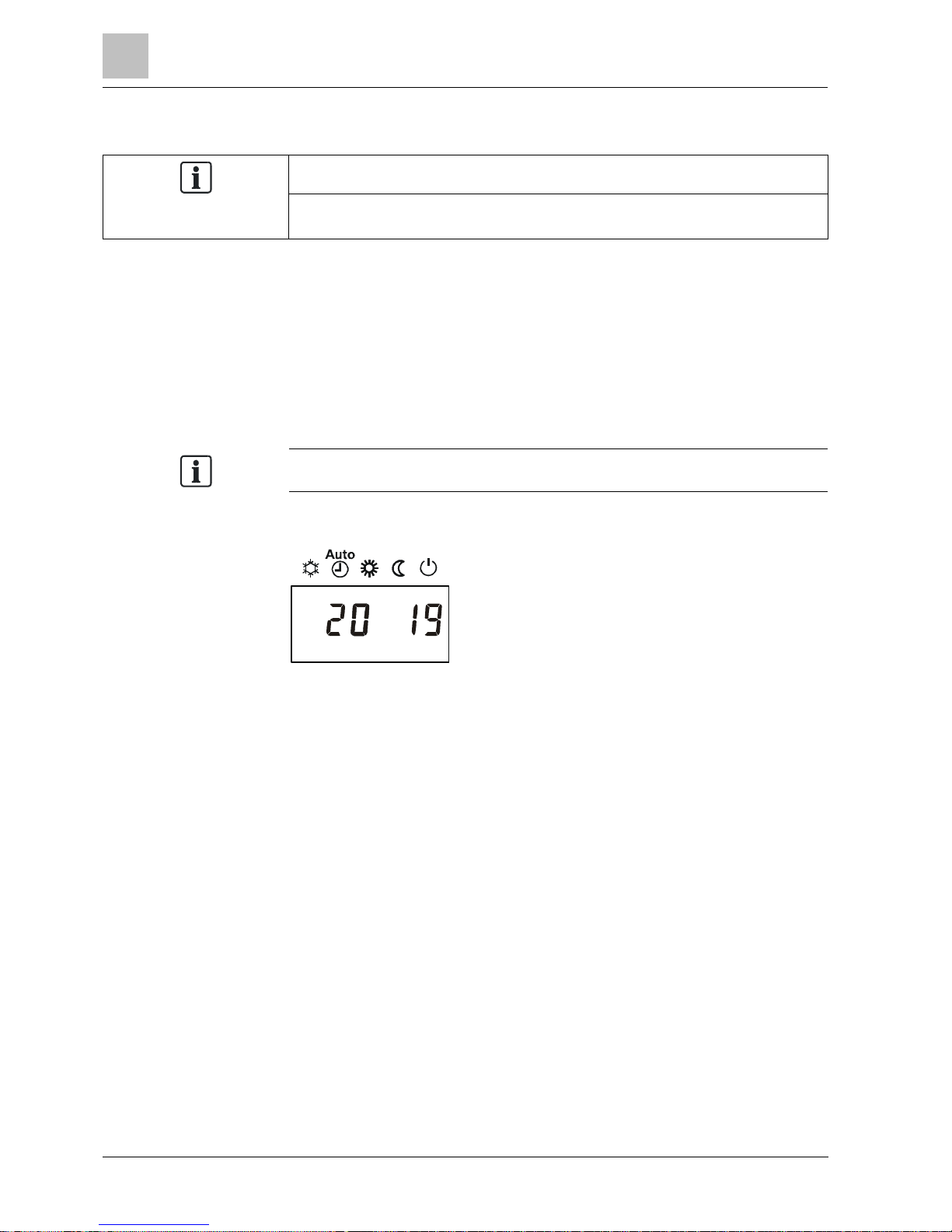
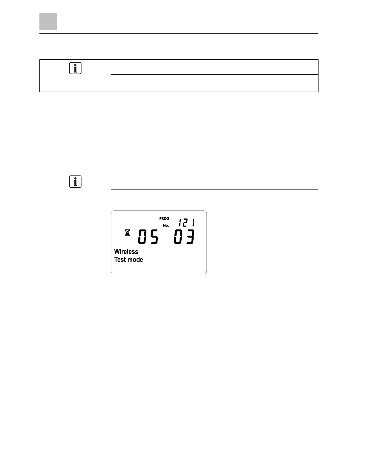
Example of a display during the test:
The test results are displayed on the display:
l The digits on the left show telegrams that have been sent, the digits on the
right telegrams that have been received.
l The test will be ended after 24 t elegrams. The test is considered successful
when at least 50% of the telegrams sent have been received.
l If the test was not successful, some other mounting location should be chosen,
or the AVS14.390 RF repeater should be used.
Testing
Mounting and installation
2
RF com
ponents
21
Siemens Operator / Room / Auxiliary devices CE1U2358en_04
Building Technologies 2014-09-26
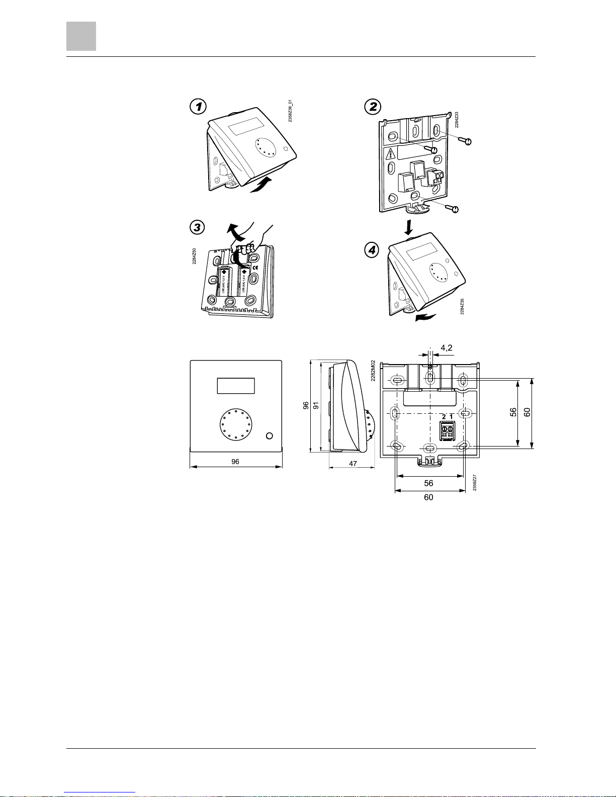
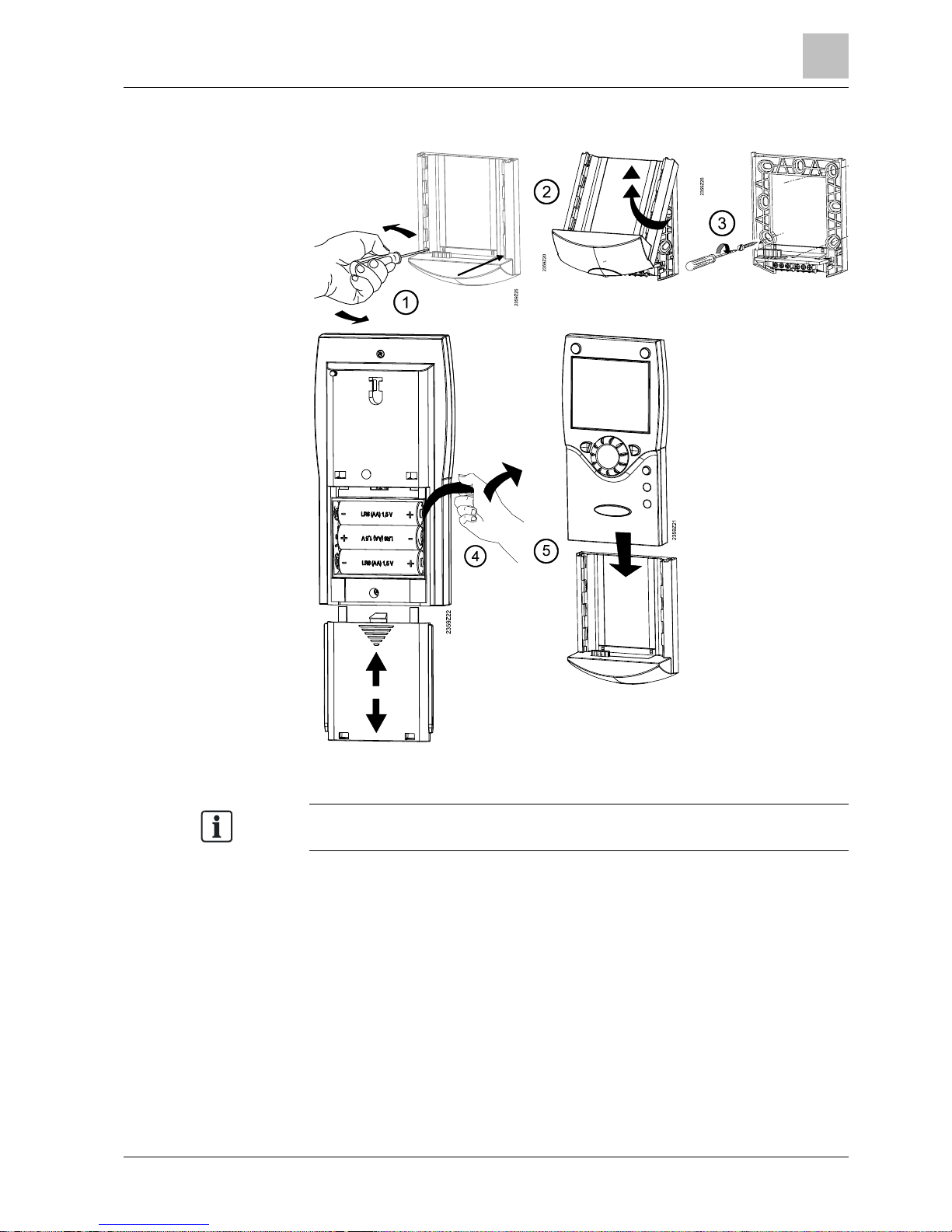
2.2.2 Room unit QA A78...
In the case of mounting with base, there must be sufficient clearance above the
unit, enabling it to be f itt ed and removed
Mounting with base.
2
Mounting and installation
RF components
22
Siemens Operator / Room / Auxiliary devices CE1U2358en_04
Building Technologies 2014-09-26
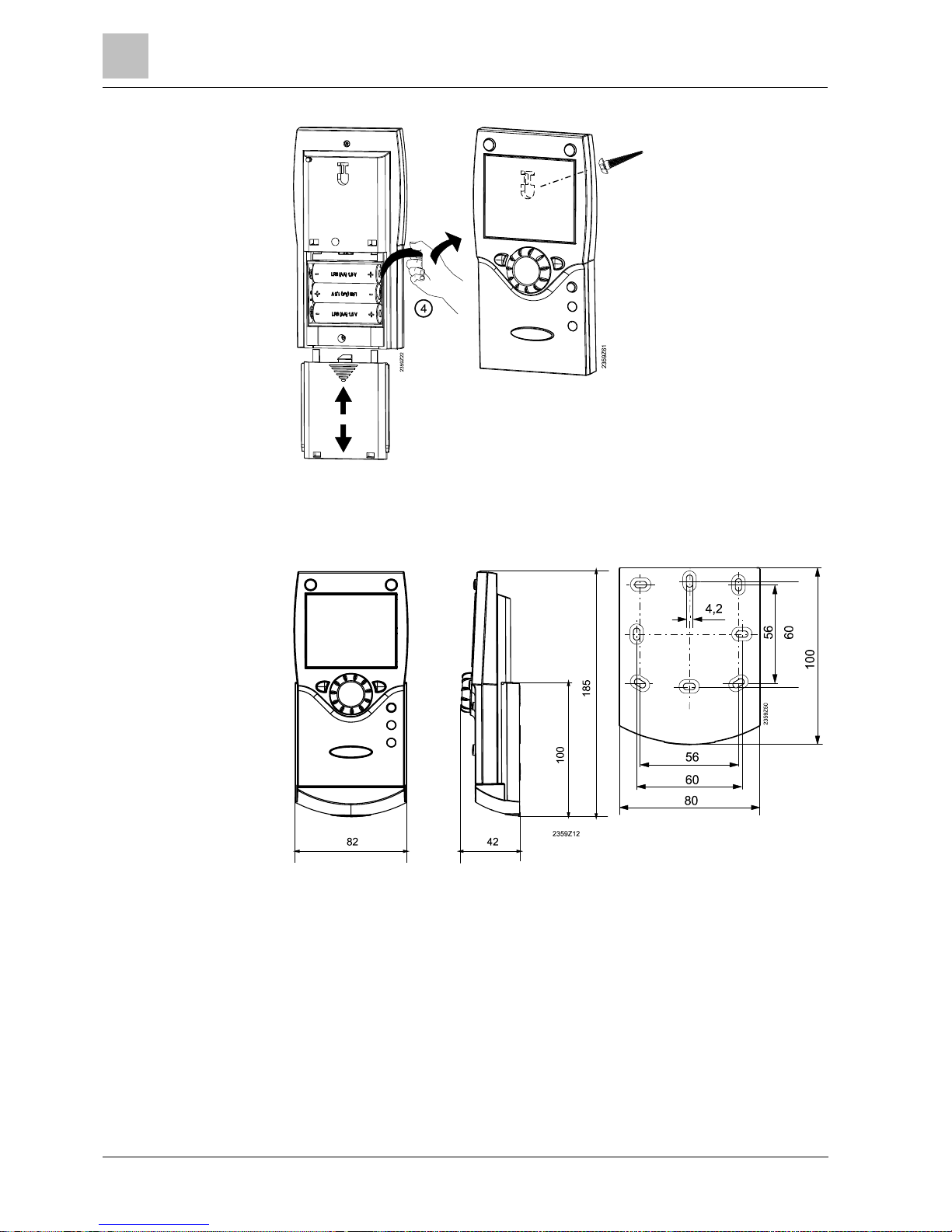
Power is supplied via three 1.5 V alcaline batteries of type AA (LR06).
Mounting without base.
Connections / power
supply
Dimensions and dril ling
plan
Mounting and installation
2
RF components
23
Siemens Operator / Room / Auxiliary devices CE1U2358en_04
Building Technologies 2014-09-26
NOTICE
●
Establish RF connection while unmounted and near the RF module (BSB).
● The base unit powers the RF module (BSB).
● T he devices battery supply must be activated (remove the battery protective
strip).
1. Press the button on the RF module (BSB) for at least 8 seconds.
a The LED on the RF module (BSB) blinks rapidly.
2. Press the OK button on the room unit.
a The room unit switches to the programming level.
3. Press the Info button for at least 3 seconds.
4. Using the knob, selec t "Commissioning" operating level and press the OK
button.
5. Using the knob, selec t "Operator unit" operating page and press the OK button.
6. Select operating line 40 "Used as" and make the proper settings.
7. Press the OK button to confirm.
8. Using the knob, select "RF" operating page and press the OK button.
9. Select operating line 120 "B inding" and press the OK button.
10. Use the sett ing knob to set to "Yes".
11. Press the OK button to confirm.
a The process of opening the connection is started.
a The display shows the progress of opening the connection in %. This process
can take 2...300 sec onds.
a The connection is established when "Device ready" appears and the LED on
the RF module (AVS71.390) turns off.
a The LED of the RF module BSB (AVS71.393) lights again after 5 seconds
(operating stat e "On").
Refer to Section
Operation [
➙
42]for button labels.
RF connection
Establishment
2
Mounting and installation
RF components
24
Siemens Operator / Room / Auxiliary devices CE1U2358en_04
Building Technologies 2014-09-26
NOTICE
●
The test is made to check the quality of the radio link.
●
Testing takes place at the final installation location.
1. On unit (as described above), select operating page "RF".
2. Select operating line 121 "Test mode" and press the OK button.
3. Use the setting knob to set to "On".
4. Press the OK button to confirm.
a Test mode begins. 24 telegrams are sent.
The test can be stopped by pr essing the ESC button
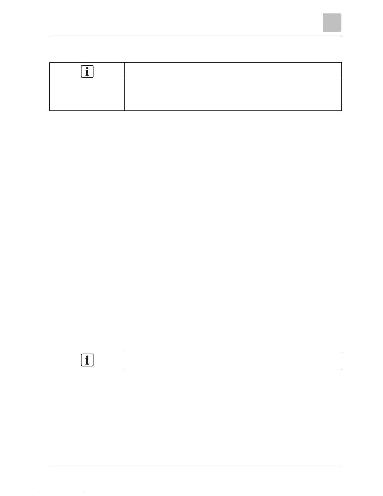
Example of a display during the test:
The test results are displayed on the display:
l The digits on the left show telegrams that have been sent, the digits on the
right telegrams that have been received.
l The test will be ended after 24 t elegrams. The test is considered successful
when at least 50% of the telegrams sent have been received.
l If the test was not successful, some other mounting location should be chosen,
or the AVS14.390 RF repeater should be used.
Testing
Mounting and installation
2
RF components
25
Siemens Operator / Room / Auxiliary devices CE1U2358en_04
Building Technologies 2014-09-26
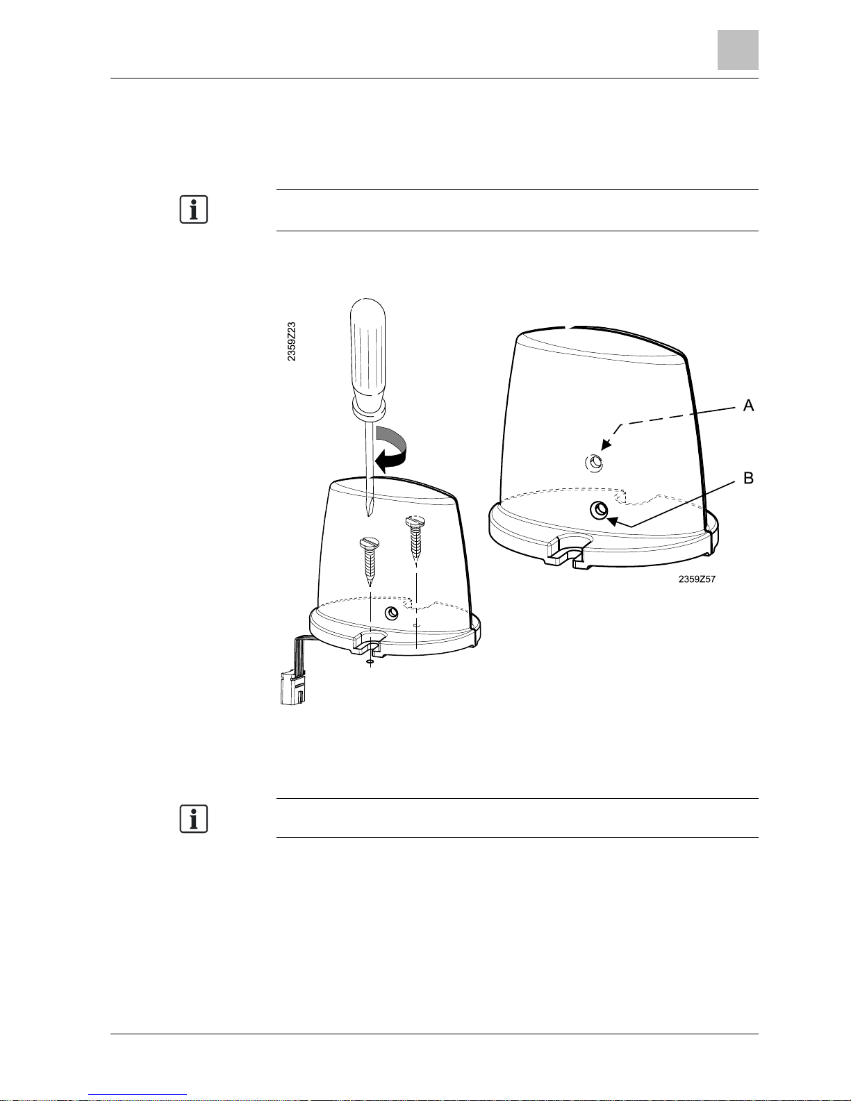
2.2.3 RF module AVS71.3 90
The RF module extends the product range by introducing wireless communication.
The RF modules allow system components, such as room units, to transmit data
without laying cables.
RF module (AVS71.390) and RF module BSB (AVS71.393)
cannot
be used
concurrently.
Do not install the unit inside metal casings (e.g. inside the boiler).
A: LED
B: Button
The cable of the RF module has a plug to connect to the controller (connection
X60).
Disconnect all power prior to connecting the basic unit!
Engineering
Installation
Terminals
2
Mounting and installation
RF components
26
Siemens Operator / Room / Auxiliary devices CE1U2358en_04
Building Technologies 2014-09-26
The RF link is establishing using the RF module as described in t he corresponding
section on RF components.
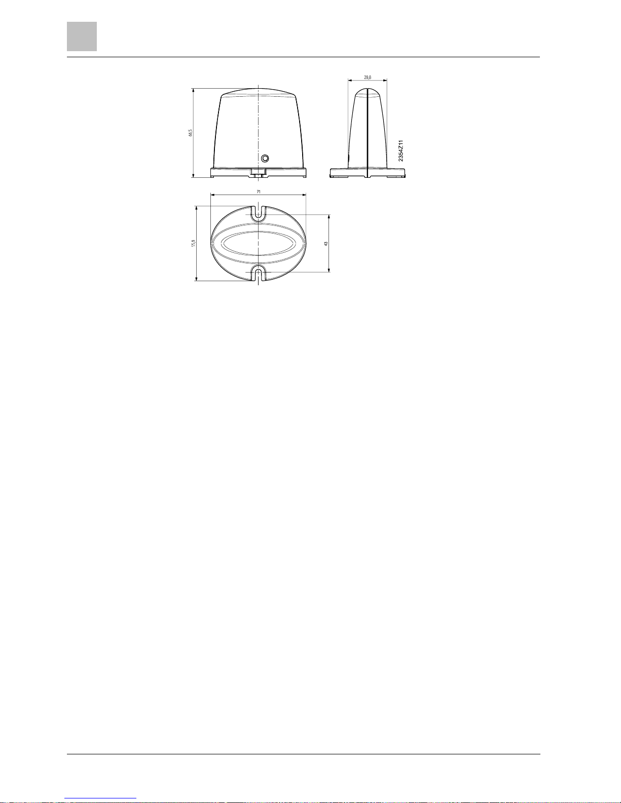
Dimensions and dril ling
plan
RF connection via RF
module
 Loading...