

Siemens QAA2391.EWTC,QAA2391.DWTC QAA2391.FWTC,QAA2391.EWNC,QAA2391.DWNC,QAA2391.FWNC Installation Instructions Manual
Installation Instructions
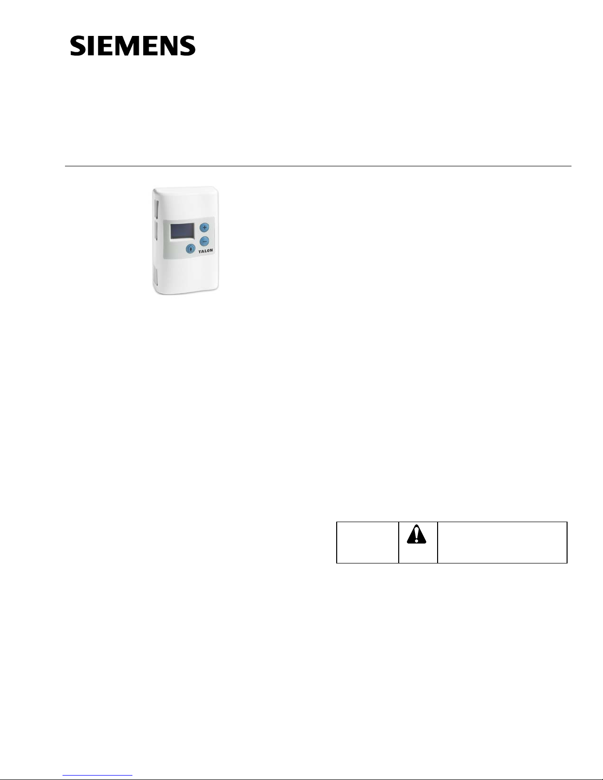
Wireless Room Sensor (WRS)
CAUTION:
Equipment damage or loss of
specified.
Figure 1. Wireless Room Sensor (Full-Featured).
Product Description
Wireless Room Sensors eliminate the need to run
wire between Terminal Equipment Controllers
(TECs) and their respective room temperature
sensor. The sensor communicates wirelessly with
the TEC using a Room Sensor Transceiver (RSX)
mounted at the TEC.
Product Numbers
Document No. 563-066
November 2, 2015
Accessories
563-207 Auto-binding cable (to bind
WRS/RSX pair)
544-643A RTS passkey (to change display to
DIAG mode)
N/A Replacement 3.6 Volts lithium AA
battery –SAFT Part Number
LS14500BA (See Field Purchasing
Guide.)
540-143 Laptop computer cable
(RJ-11 to DB-9)
141-570 Lockable Thermostat Guard,
vented clear plastic.
Related Products
563-069 Room Sensor Transceiver (RSX)
563-007 Direct Mount Antenna (for RSX)
563-008 Remote Mount Antenna (for RSX)
563-210-01 RSX/TEC Connection Cable (3 ft)
563-210-02 RSX/TEC Connection Cable (10 ft)
TALON® Logo
QAA2391.EWTC Wireless Room Sensor (WRS) –
Sensing only
QAA2391.DWTC Wireless Room Sensor (WRS) –
Sensing with temperature
display
QAA2391.FWTC Wireless Room Sensor (WRS) –
Sensing with override, setpoint,
and temperature display
No Logo
QAA2391.EWNC Wireless Room Sensor (WRS) –
Sensing only
QAA2391.DWNC Wireless Room Sensor (WRS) –
Sensing with temperature
display
QAA2391.FWNC Wireless Room Sensor (WRS) –
Item N umber 563-066, Rev. DA Page 1 of 4
Sensing with override, setpoint,
and temperature display
Expected Installation Time
10 minutes
Caution Notations
data may occur if you do not
follow a procedure as
Prerequisite
Install the associated transceiver per the Room
Sensor Transceiver (RSX) Installation Instructions
(563-067).
Document No. 563-066
CAUTION:
CAUTION:
Installation Instructions
November 2, 2015
Required Tools
• Phillips screwdrivers, sizes 1 and 2
• Medium and small flat-blade screwdrivers
• 1/16” hex key
• Medium-duty electric drill and 3/16-inch
(4.8 mm) drill bit
• Small level and tape measure
NOTE: Depending on the actual installation
(surface mounting) some of these tools
may not be required.
Binder Instructions
Do not mount the WRS within 10 feet of
other RF devices such as microwave
ovens, Wi-Fi/802.11 access points, and so
on.
1. Remove the plastic insulating strip between the
battery in the WRS battery holder (or insert the
battery) to power up the WRS.
NOTE: Even though the WRS is powered, it
stays in a low-power sleep mode until
commissioned.
Binding Using HMI Commands
To bind your WRS to its associated RSX using HMI
commands, follow these steps:
1. Connect a PC cable (540-143) from a computer
to the RJ-11 port on the bottom of the WRS.
2. Start a HyperTerminal session, log on (1200
baud, 8 data bits, no parity, 1 stop bit, no flow
control), and then press ENTER to display the
WRS prompt.
3. At the WRS HMI prompt, type
BIND RSX a (where a = EUID of the RSX), and
then press ENTER.
When binding is succ ess f ul, the LED on the RSX
turns solid yellow, and the WRS initiates a
communication check with the RSX to verify link
quality.
When successful, remove the computer cable from
the WRS. By default the HMI will time out after five
minutes. Remove and reinsert plug to reactivate.
For additional information on using HMI commands
to change the default configuration, troubleshoot
binding, placement or other diagnostics, see the
Wireless Room Sensor Solution User’s Guide
(563-068).
2. Bind WRS to associated RSX using optional
auto-binding cable (part number 563-207) or
HMI command.
NOTE: Verify associated RSX is installed and
Binding Using Auto-Binding Cable
To bind your WRS to its associated RSX using the
optional auto-binding cable, follow these steps:
1. Using the Auto-binding cable (563-207), plug
2. Plug the other cable connector into the RJ-11
3. If the RSX indicator light does not immediately
When binding is successful, the indicator light on the
RSX turns solid yellow. When successful, remove
the auto-binding cable.
Page 2 of 4 Siemens Industry, Inc.
If the WRS has an LCD panel, the
displayed value does not change until
the WRS is bound to an RSX.
powered up before binding.
the connector labeled Room Sensor Port into
the RJ-11 port on the WRS.
port on the RSX.
turn solid yellow, power cycle the RSX to enter
binding mode.
Mounting Instructions
If the WRS cannot communicate with its
RSX for an extended period of time due to
the RSX not being commissioned or the
RSX is out of range, remove the battery to
avoid excessive battery drain.
1. Select a location for the WRS, following the
standard rules for room temperature sensor
placement.
Always mount the sensor vertically. Locate the
sensor as follows:
• No further than 100 feet (30 m) from the
RSX, ideally in a location where there are no
major RF obstructions (for example, metal or
concrete walls) between the two devices.
• Per design specifications, and local
regulations.
• Where the air circulates around it freely (not
in recessed areas or behind doors).
• Allow a minimum of 4 inches (10 cm) free
space above and below for the front cover
removal tool and to allow proper airflow.
 Loading...